Simulating Eye Reaction to Light With a Photocell. Processing. Arduino.
by mikesevd in Circuits > Arduino
1961 Views, 14 Favorites, 0 Comments
Simulating Eye Reaction to Light With a Photocell. Processing. Arduino.


In this project you can see a simple example of using processing in order to make a graphic representation of data that an arduino gets as input from a sensor. In this case a photocell.
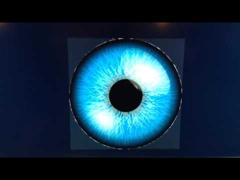
After getting an eye picture from internet, what I did is, make with processing a black circle (and also filling black the area within) that has a radious inversely proportional to the amount of light that the LDR gets. So the graphic iris increases as the light decreases (such as a real iris would do!). There is no precise analogy to the real iris functioning, although I cannot imagine - in case the right data were available- why, shouldn't that be possible!
Preparing the Arduino Hardware

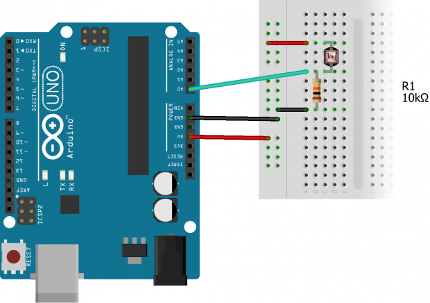
The first thing to do is to make the appropriate hardware with arduino (or whatever...). In this case is the simplest circuit that an arduino gets light measurements from an LDR.
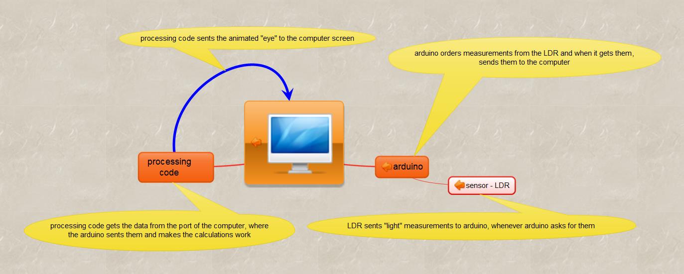
In order to send data to the processing software must be a Serial.print(light_measurement) type of command, where the "light_measurement" is the variable for storing the light measurement for every loop of the arduino code. With this command the data are send to the port from where is should be get from the processing software.
Arduino Code
After completing the hardware it's time to prepare the right code so that the light measurements could be taken and then used from the processing software that produces the iris movement that you see in the video.
int sensor = A0,light;
void setup() {
pinMode(sensor, INPUT);
pinMode(3,OUTPUT); // this is an optional add-on so that the change of light intensity brings a change of
//blinking rate of a power LED
Serial.begin(9600); }
void loop() {
light = analogRead(sensor);
float val = (5.0/1024.0)*light; // with this calculation the val parameter varies in the range 0-5
Serial.println(val); // val is the variable sent to the port where the arduino is connected and is going to be
// taken from the processing code
blinkLED(3,light); }
void blinkLED(int pin,int duration) {
// this routine blinks the LED connected to dig pin 3 with a rate analog to light level
digitalWrite(pin,HIGH);
delay(duration);
digitalWrite(pin,LOW);
delay(duration); }
Processing Code
The following code is the processing code (with the open source software from https://processing.org/
- Thank God!) which I think is one of the simplest with serial communication. Suitable to start with!
import processing.serial.*;
// import the appropriate libraries for the serial communication between the processing code and the data // coming from the arduino (or whatever!)
Serial myPort;
PImage eye;
PrintWriter writer;
void setup() {
size(1400,800);
eye = loadImage("Eye-4.jpg"); // gets the image from the folder where the processing exe is
myPort = new Serial(this, Serial.list()[0], 9600);
// locates the port from where the variable data should be taken
myPort.bufferUntil('\n');
background(0,26,51); }
void draw() {
String inString = myPort.readStringUntil('\n');
if(inString != null) { // "if you get some characters..."
inString = trim(inString); // trim whitespace
float inByte = float(inString); // convert to a number
print(" inByte= "); println(inByte); // optional : if you want to check the variables to be used
inByte = map(inByte, 0, 5, 0, height); // map to screen height
print(" mapped inByte= "); println(inByte);
// optional : if you want to check the variables to be used
image(eye,400,150,600, 600); // the picture of the eye is brougth on the screen
int radious = 500 - round(inByte);
// makes the radious inversely proportional to the light measure
fill(0); // fills black the area of the upcoming circle
ellipse(700,450,radious,radious); // makes the circle of variable radious
}
}
Important Tips!
There are a few thinks to keep in mind in order to avoid unecessary trouble!
- The baud rate both in the arduino code and the processing code shoud be the same (9600 in this case).
- Even if somebody does this, should be also careful of the delays (delay command) that includes in both codes. I managed that with experimenting. For a example there should be some delay in the arduino code, according to the type of sensor used, so that the sensor has time required to do the measurement! But the processing code shoud have suitable for that rate delay.
- The sequence of running the codes is: first the arduino code (without opening serial printing view!) and then the processing code. In case somebody wants to make some changes to the arduino code, the processing code should be stopped and after the changed arduino code is launched again the processing code should be run again too!
Best wishes and have fun!!
Eye Image for to Make the Same Project
