Phone Stand for Digitizing the Outdoors in 3D
by lynnadeng in Workshop > Science
9088 Views, 39 Favorites, 0 Comments
Phone Stand for Digitizing the Outdoors in 3D

Inspired by citizen science photogrammetry programs such as CoastSnap, we wanted to use citizen science photographs to monitor the Los Angeles River over time and better understand flooding. By attaching this system to a bridge on the river, community members walking by can put their phones onto the phone holders and help us take photos of the river.
With two phone holders, our system is a “stereo vision” system. Just as our two eyes’ slightly different views allow us to perceive how far objects are from us, this system’s two camera angles allow us to reconstruct the 3D scene of a community member’s photographs using specialized computer software.
This Instructable will take you through how we built our system, but you can easily adapt the attachment methods or change the number of holders to create your unique system!
Supplies
Hardware Supplies
- 1 x 1x8 hardwood, at least 16" (link to product used)
- 1 x 0.06" stainless steel sheet metal, at least 5"x8"
- 8 x 1/4"-20 steel screw-to-expand inserts for plastic (link to product used)
- 8 x 1/4"-20 1" fully-threaded machine screws (link to product used)
- 4 x 1/4"-20 1.5" bolts (link to product used)
- 4 x 1/4"-20 steel hex nuts (link to product used)
- 4 x 1/4"-20 washers
- PLA 3D printing filament
Hardware Tools
Many of the tools used could easily be replaced – read further to see how these tools were used and consider viable alternatives!
- FDM 3D printer
- Miter saw
- Waterjet
- CNC milling machine
- Drill press
- Clamps
- Wrench
Software
- MATLAB version 2023a, including:
- Computer vision toolbox
- Machine learning toolbox
- LIDAR toolbox
Determine Attachment System
Take measurements of the surface onto which you plan to attach your phone holders and determine the best attachment system – directly nailing, brackets, etc. You can use your phone to get an approximate preview of what the view will look like!
We decided to attach our system to a bridge overlooking the Los Angeles River, with the phone holders pointing downwards to capture as much of the river as possible. After measuring the bridge’s railings to be 4 inches by 0.8 inches, we chose to build custom offset brackets to attach our system.
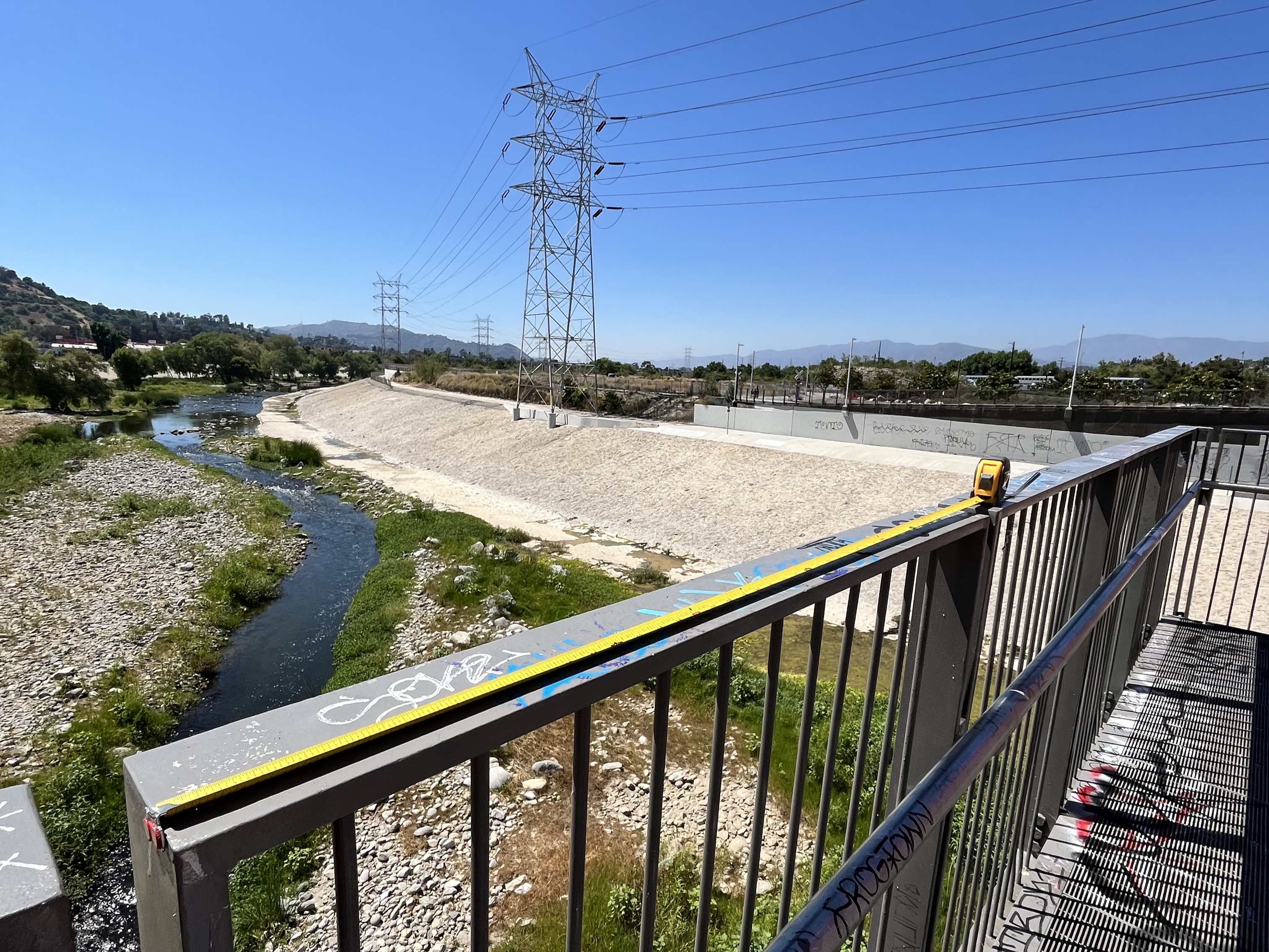
Measuring the Los Angeles River bridge
Print Phone Holders
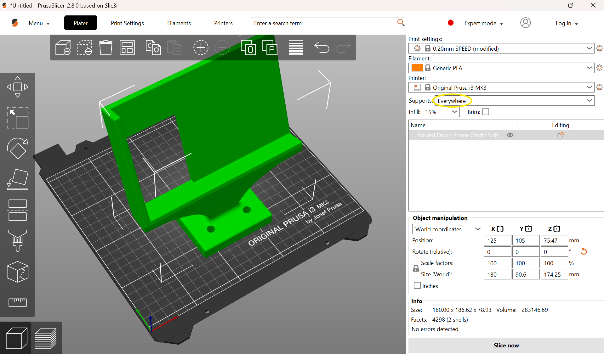
Bring the phone holder STL file attached to this step into your 3D printing slicer of choice. Here, we are using PrusaSlicer 2.8.0.
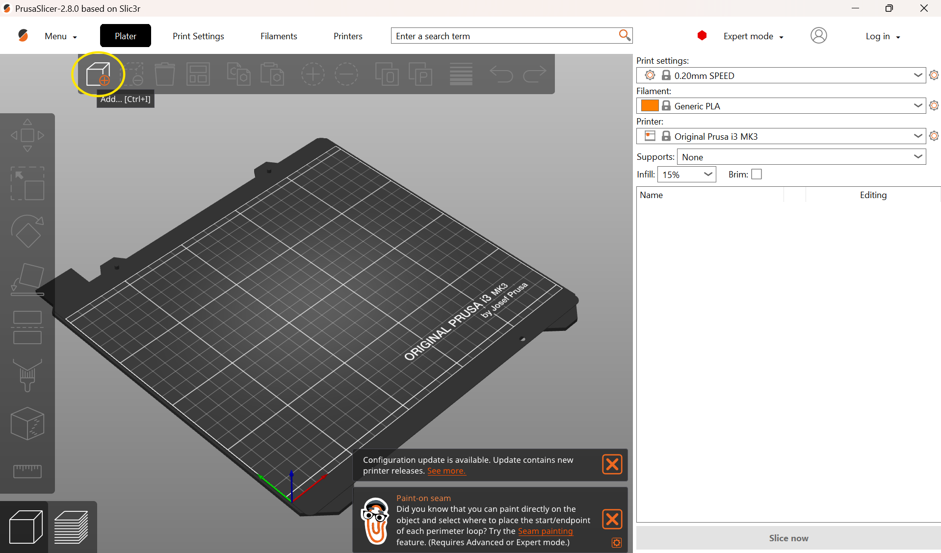
Screenshots of bringing STL file into PrusaSlicer 2.8.0
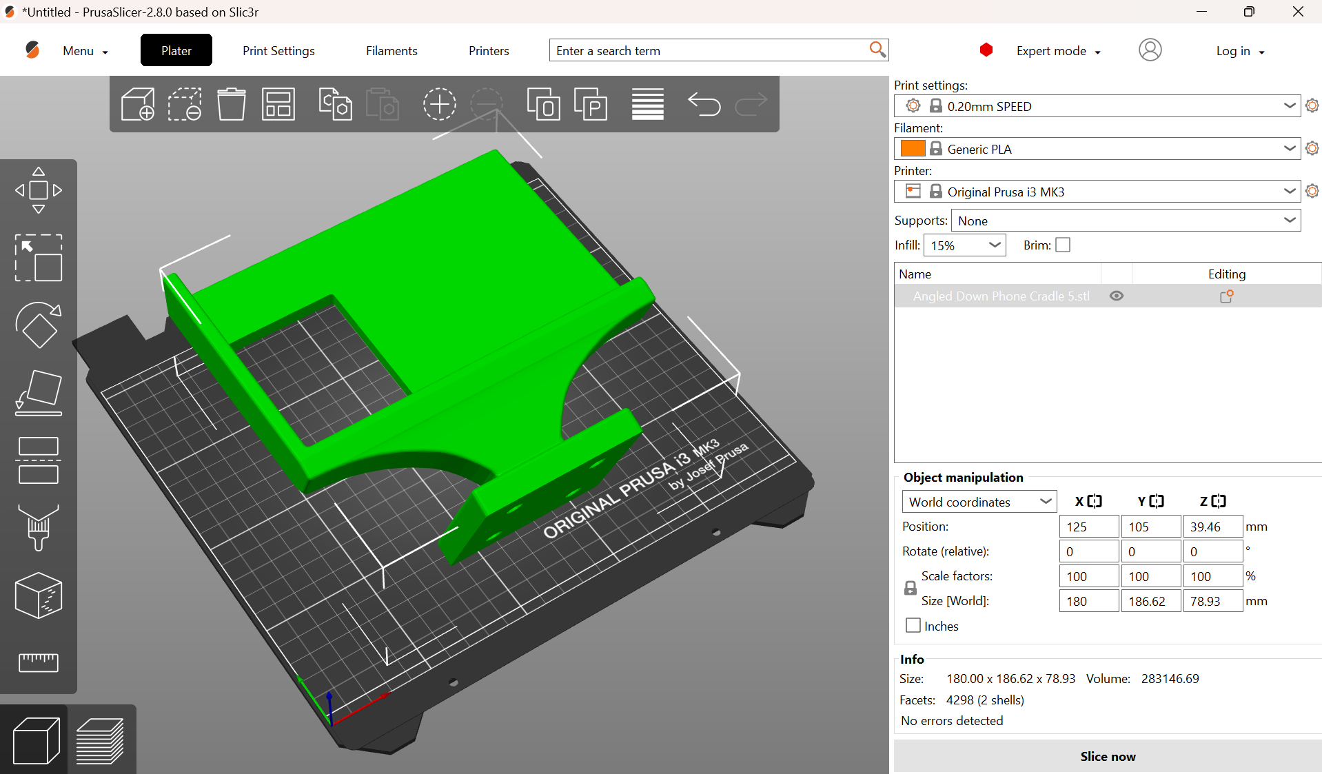
To ensure the bottom surface of the phone holder is smooth, make sure to print them upright.


Screenshots of placing holder upright in PrusaSlicer 2.8.0
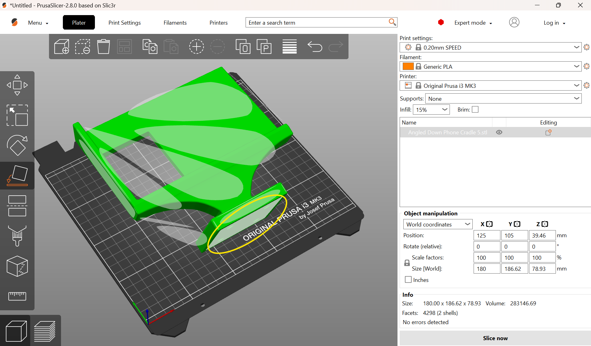
Add supports on the overhanging sections, but be careful to keep the supports around the holes to avoid filling them in. The supports added below ended up being overkill, so I would suggest painting on supports only on the overhang below the holder. If you do not mind the excessive supports, you can directly use the 3MF (can be imported into your slicer of choice) or GCODE (can be directly used to print) files attached below.
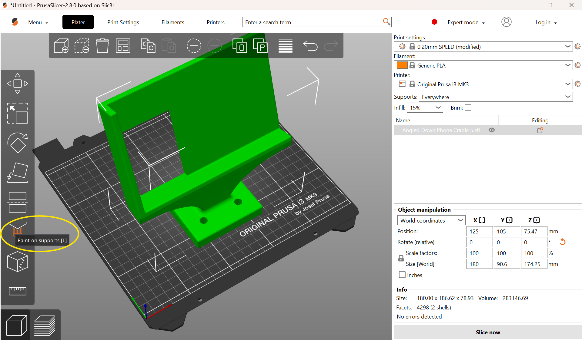
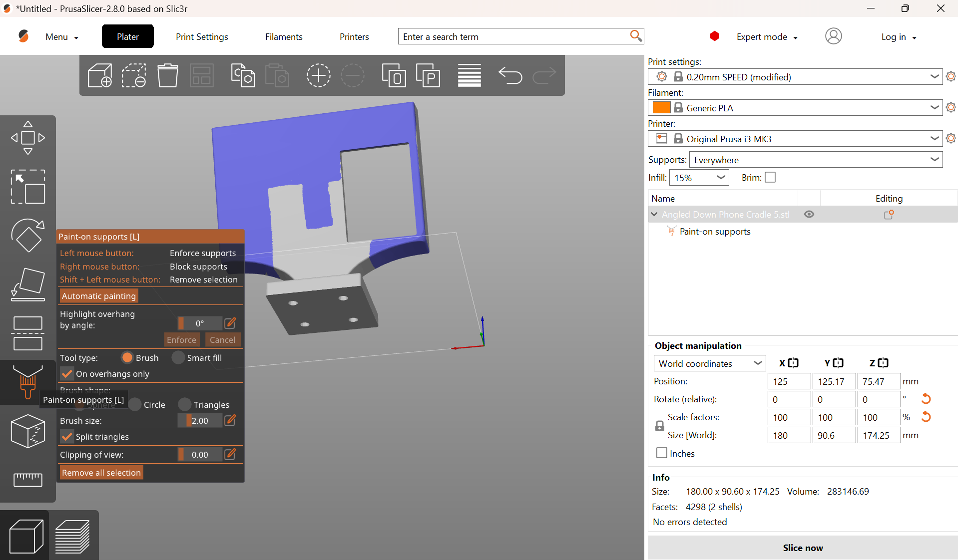
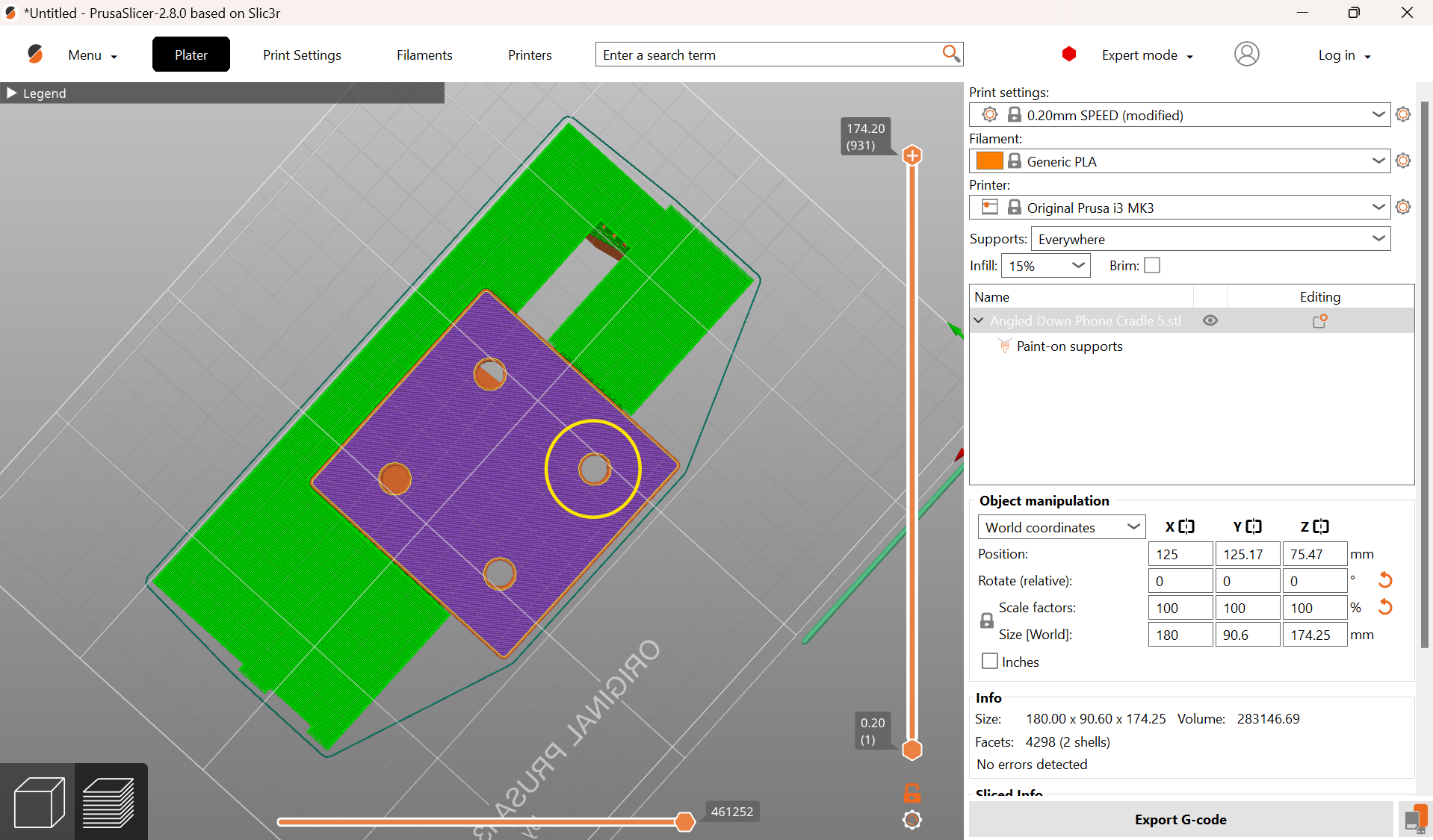
Screenshots of painting supports in PrusaSlicer 2.8.0
With the Prusa i3 MK3S printer we used, we found that starting with the “0.20 mm SPEED” preset with the following edits worked well:
- Infill: 15%
- Infill pattern: Gyroid
- Perimeters: 4
- Support top interface layers: 3
- Support bottom interface layers: 3
- Seam placement: Aligned
- Elephant foot’s compensation: 0.3 mm
Insert Screw-To-Expand Inserts
Push the screw-to-expand inserts into the holes in the bases of the printed phone holders. These holes were intentionally printed to fit the inserts snugly, so you may need the help of clamps to install the inserts.
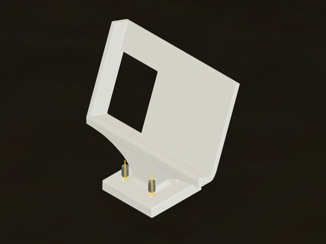
CAD drawing of how screw-to-expand inserts go into 3D prints
Chop Wood Down to Size
Most 1x8 wood is sold in 6-foot, 8-foot, or 10-foot-long pieces. Cut the wood to approximately 16" in length and sand any rough surfaces. A miter saw works well for this.
Drill Holes Into Wood for Attaching Holders
Using the CNC files attached to this step, drill half an inch into the wood plank at each of the eight points highlighted below. A 3/16" drill bit is ideal, as this is approximately the inner diameter of a 1/4"-20 machine screw, allowing the screws to “bite” into the wood as they are inserted.
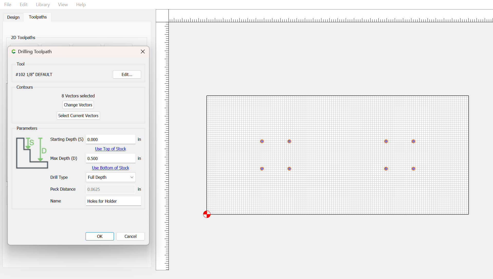
Screenshot from Carbide Create of CNC file for drilling into wood for attaching phone holders
Cut Brackets Out of Sheet Metal
Using the DXF file attached to this step, use a waterjet cutter to cut a rectangle from the steel sheet metal. Repeat to produce enough for two brackets.
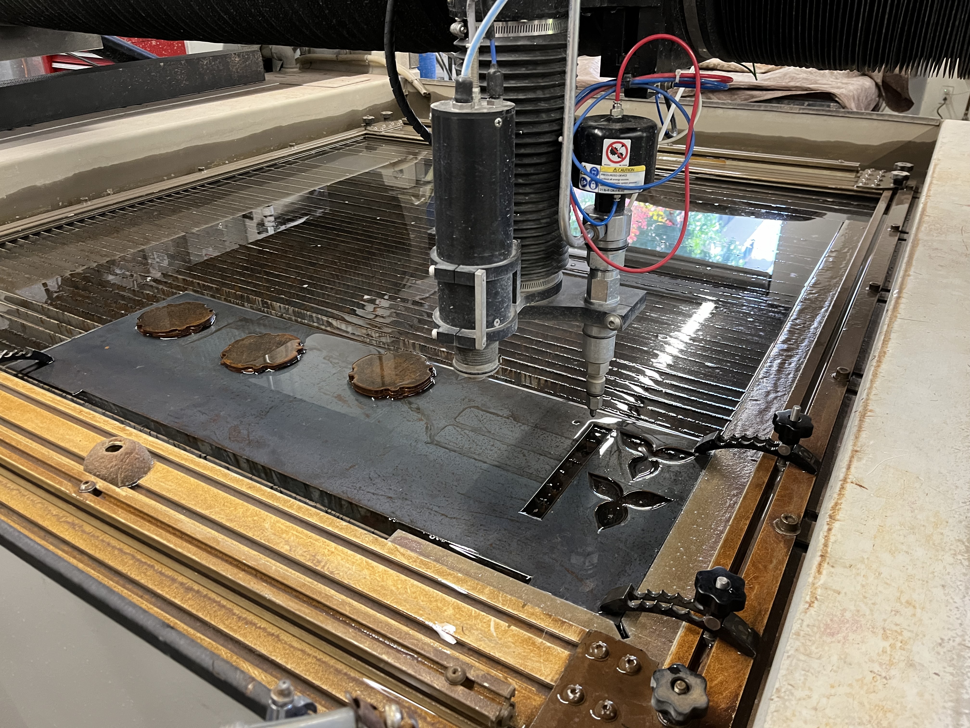
Set-up for using waterjet to cut brackets from sheet metal
Downloads
Deburr Brackets
Deburr the edges and corners of the metal pieces to prevent anyone from getting hurt handling the pieces.
Bend Brackets
Using a large clamp or a jig, hold a metal piece vertically at about 1.4 inches from one end. Bring a 1/2/3 block next to the metal piece to check that it is perfectly vertical.
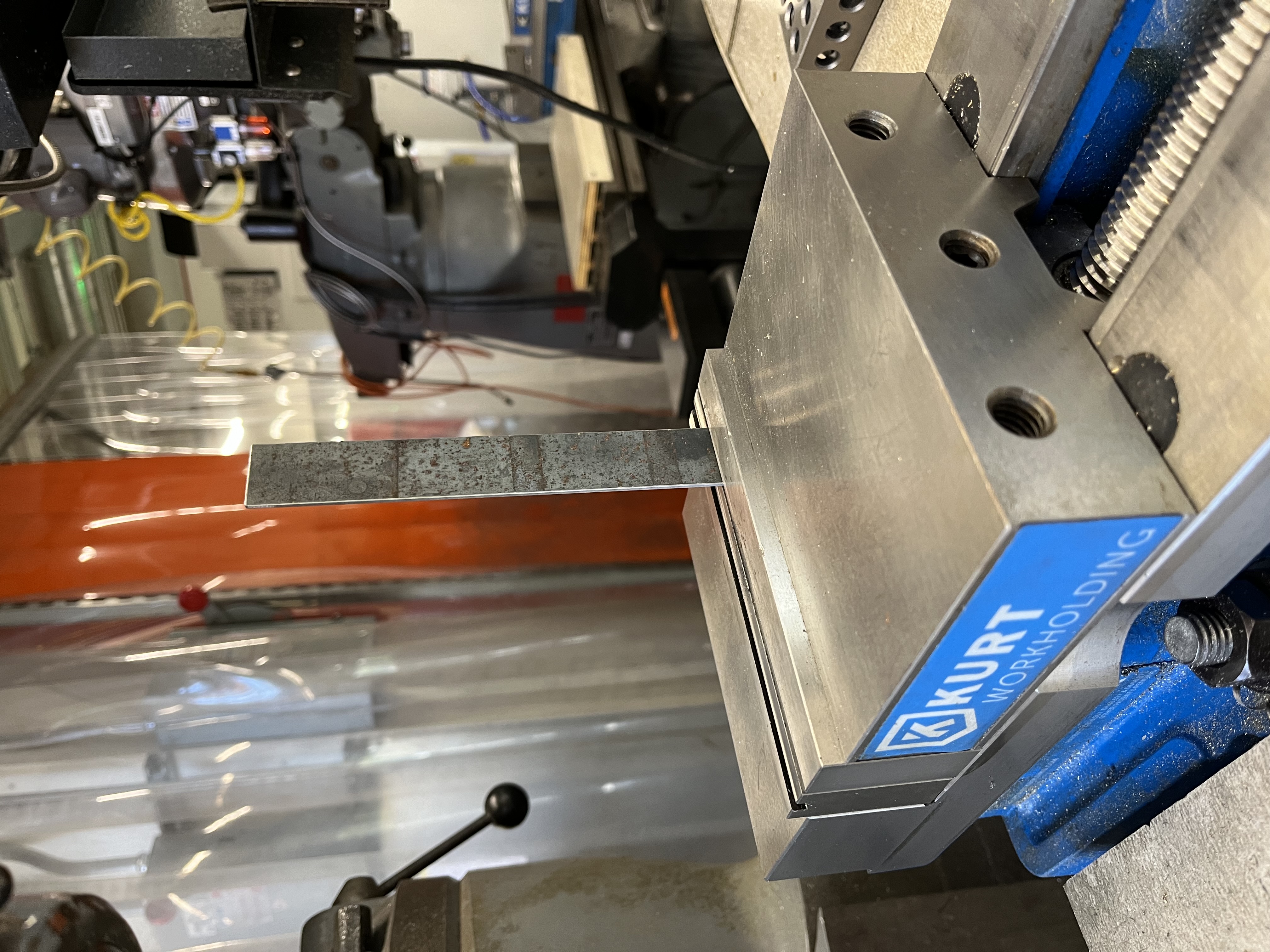
Metal piece vertically placed in jig
Knock the metal piece as close to the clamp or jig as possible using a mallet until it is bent at a 90-degree angle.
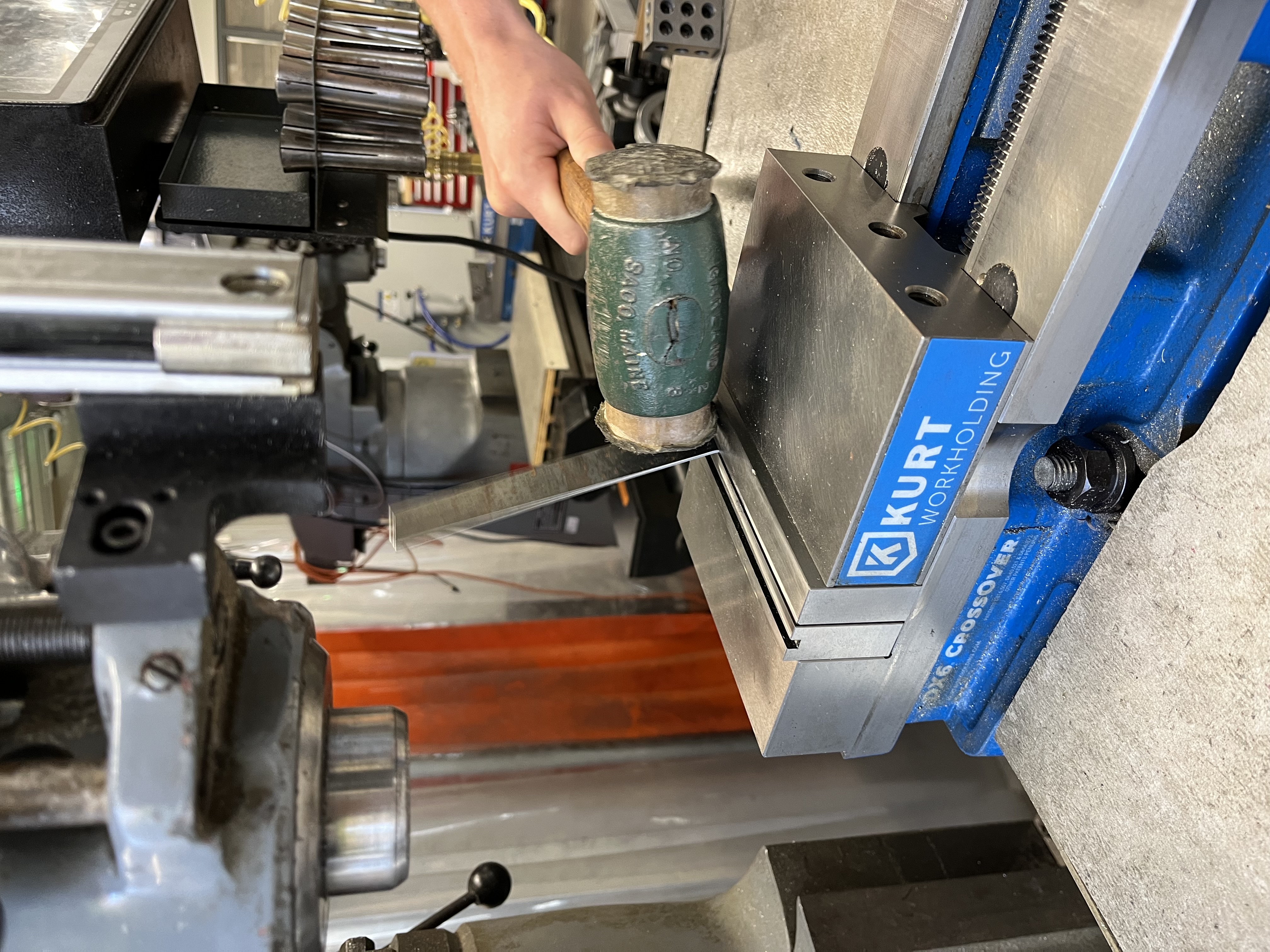
Making first bend
Repeat on the other side.
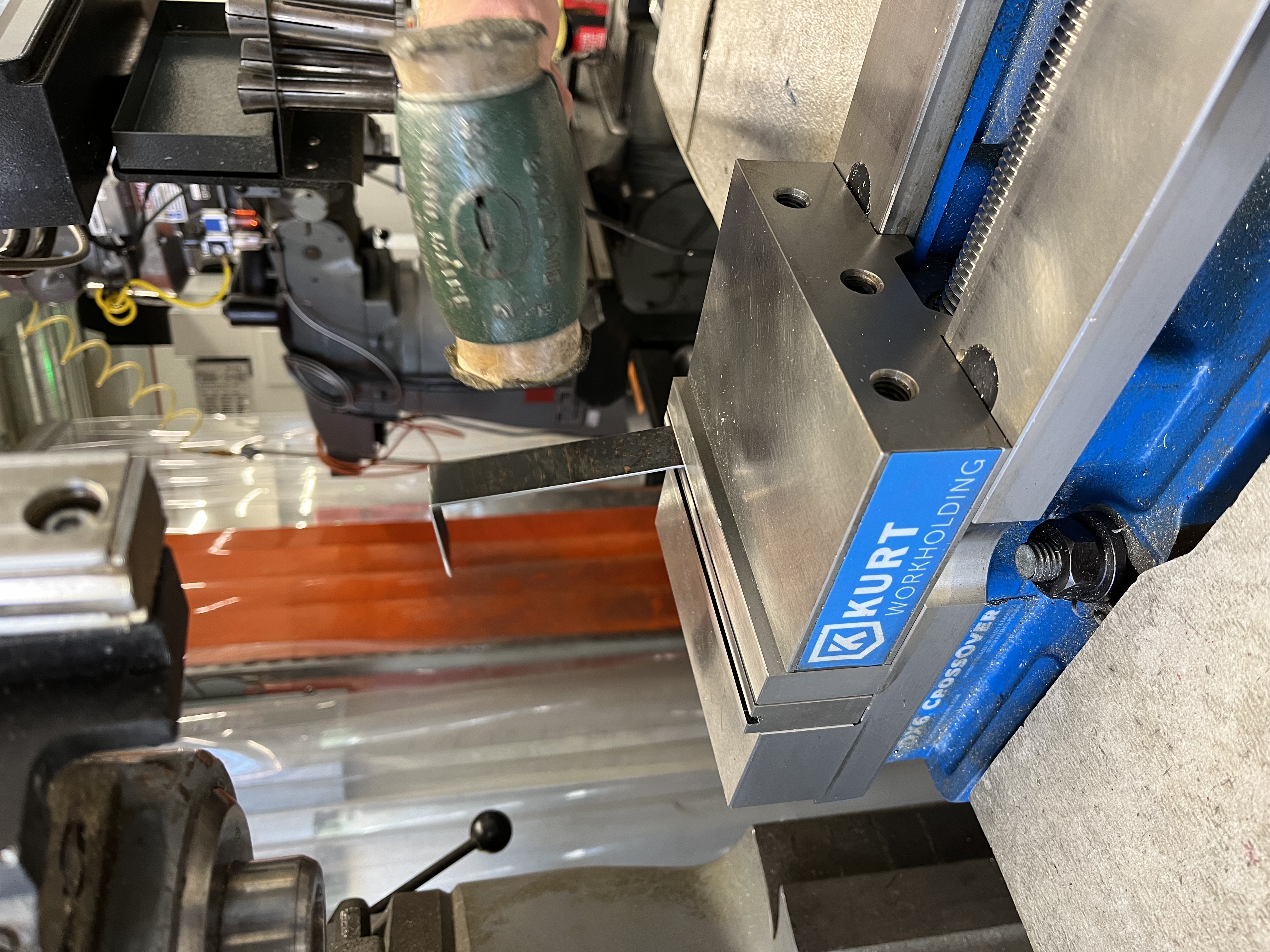
Making second bend
Widen the clamp or jig until it is width of the bracket. Add supporting materials inside the clamp or jig such that the bracket is lowered to the desired depth. Knock both protruding sides of the metal piece until they are bent at 90-degree angles, creating tabs.
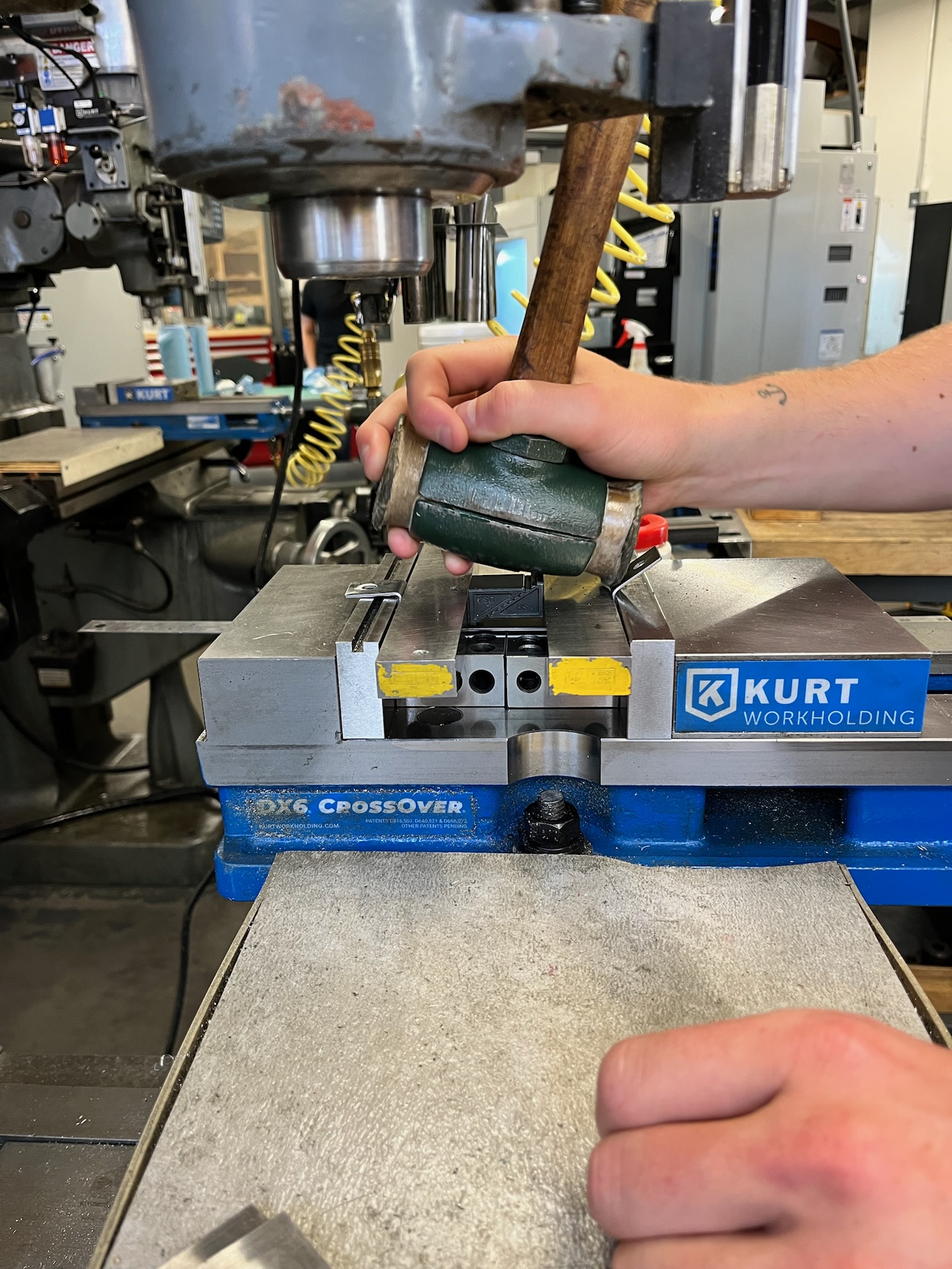
Making tabs on both sides
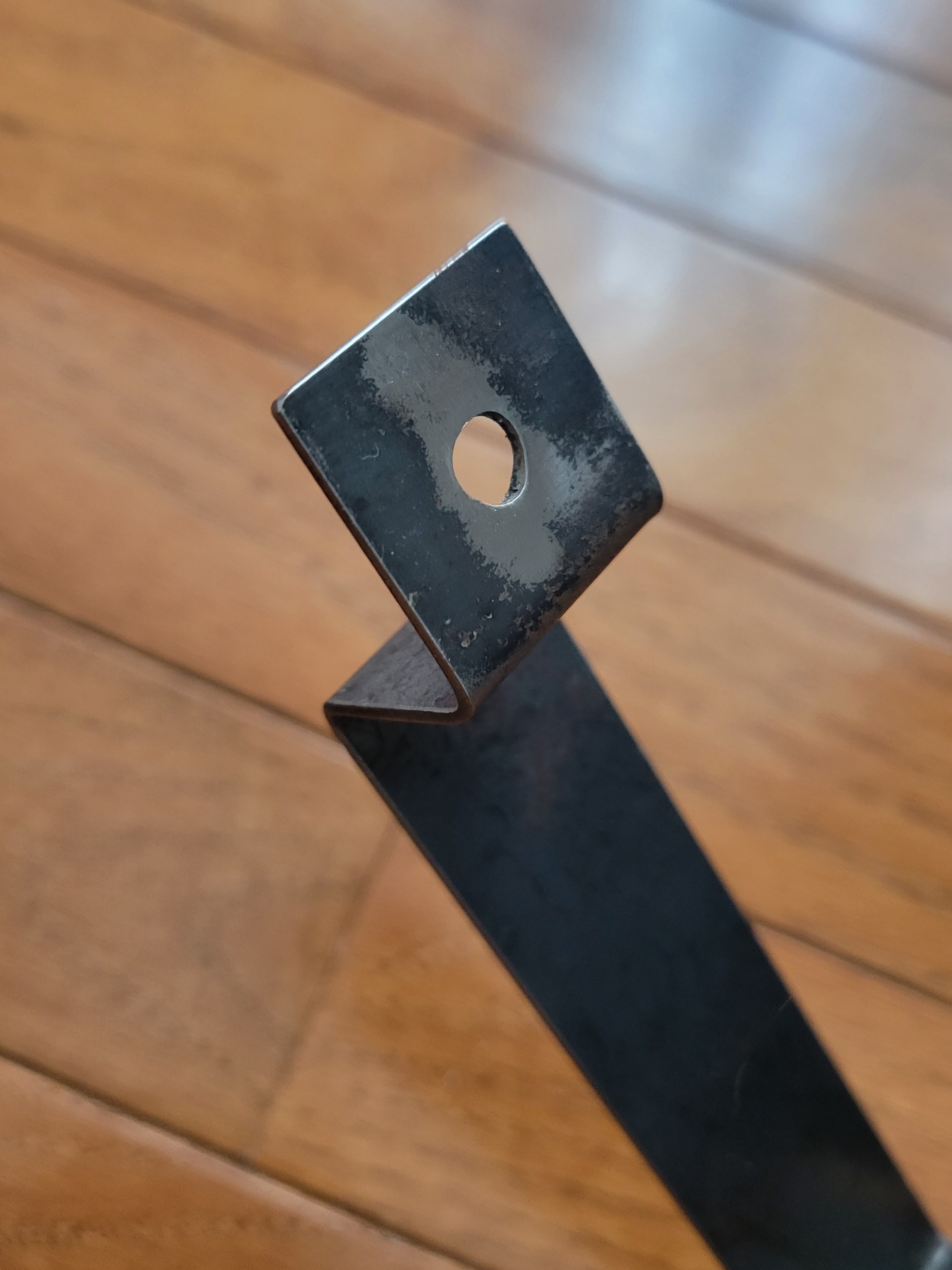
The final bracket should look like this:
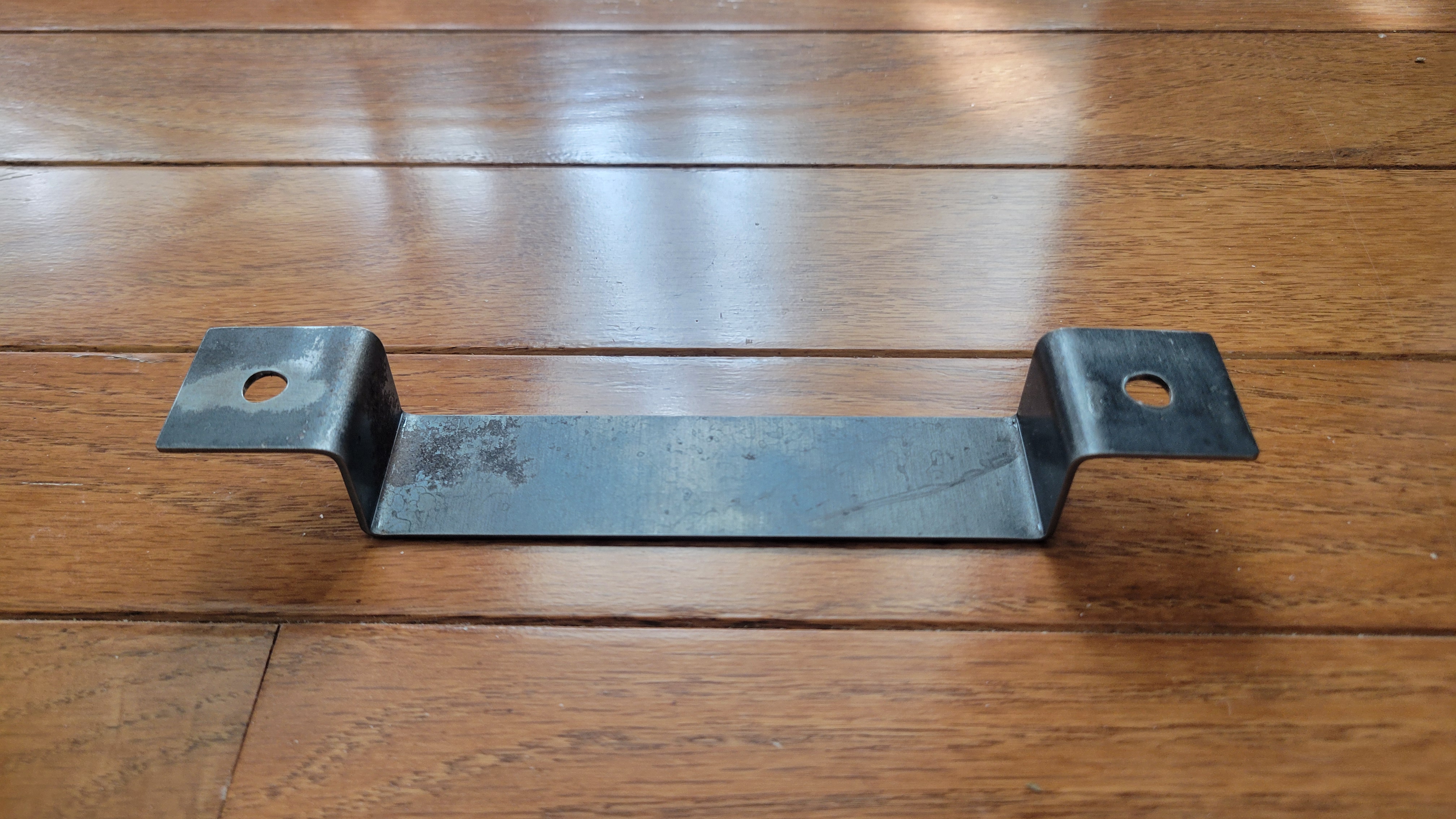
Final bent bracket!
Drill Holes Into Brackets
Place the brackets on top of parallels and into a metal drill press with a 0.5" drill bit. Drill holes roughly into the centers of the tabs.
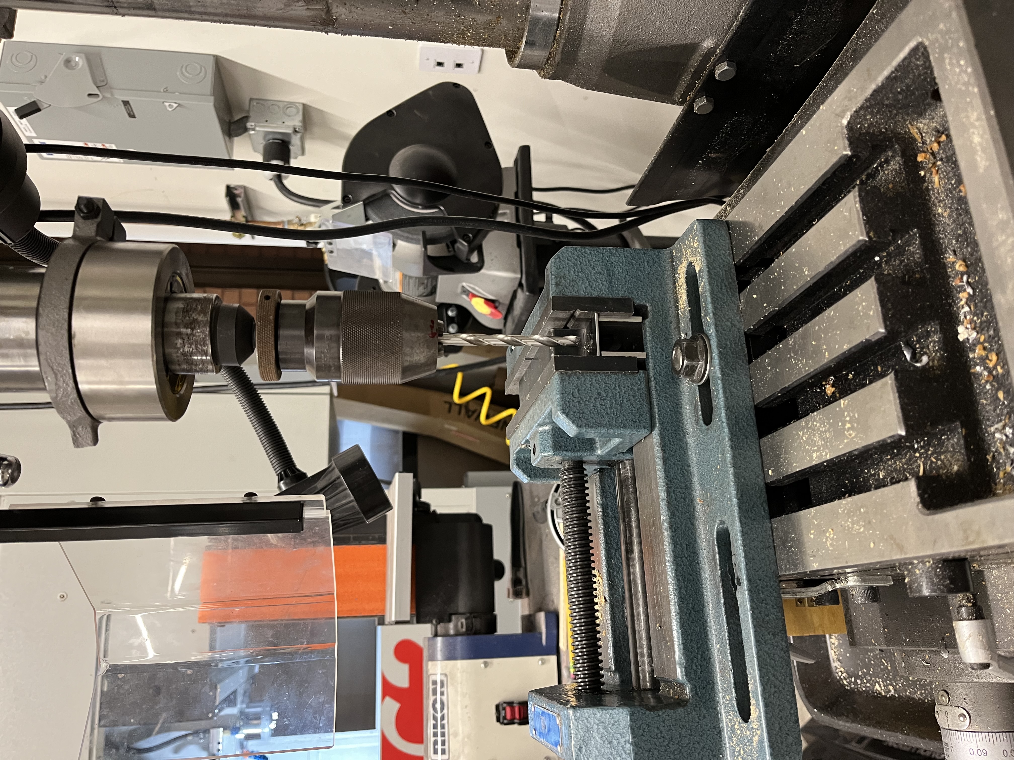
Using drill press to create holes in brackets
Deburr Bracket Holes
Use an airgun to blow off any metal shards and deburr the holes drilled.
Deburred bracket holes, close up
Drill Holes Into Wood for Attaching Brackets
Align the brackets on the underside of the wood plank such that they are approximately 0.5" from their respective short edges of the plank. Use a permanent marker to mark the centers of the holes.
Clamp the wood into a drill press fitted with a 0.5" drill bit and drill completely through at each of the four marked points.
Attach Holders
Insert the eight 1" machine screws through each of the inserts and into the wood, using a wrench to ensure they are flush with the holders. A clamp may be useful for keeping the holders flush with the wood.
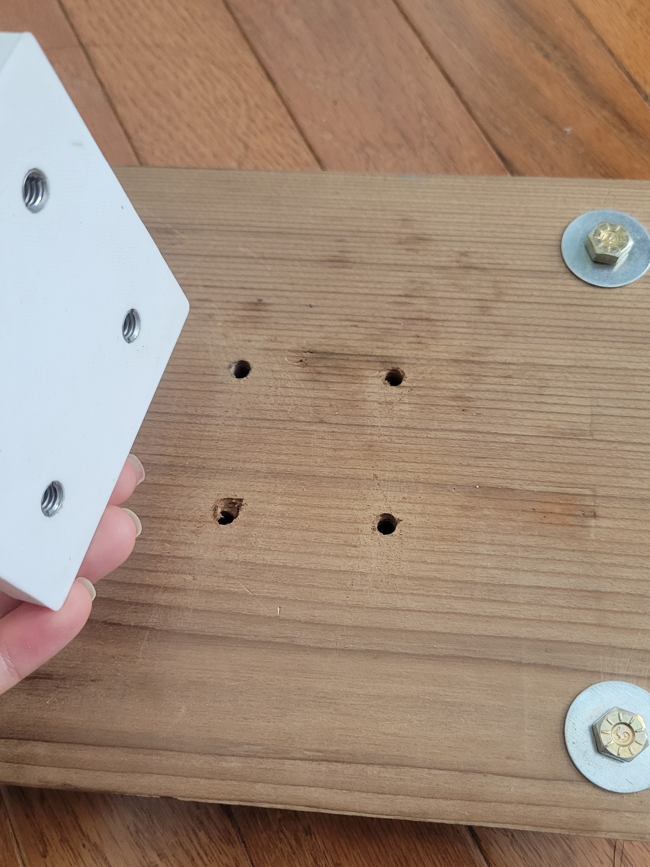
Aligning holes in holders and wood
Using wrench to fully tighten screws
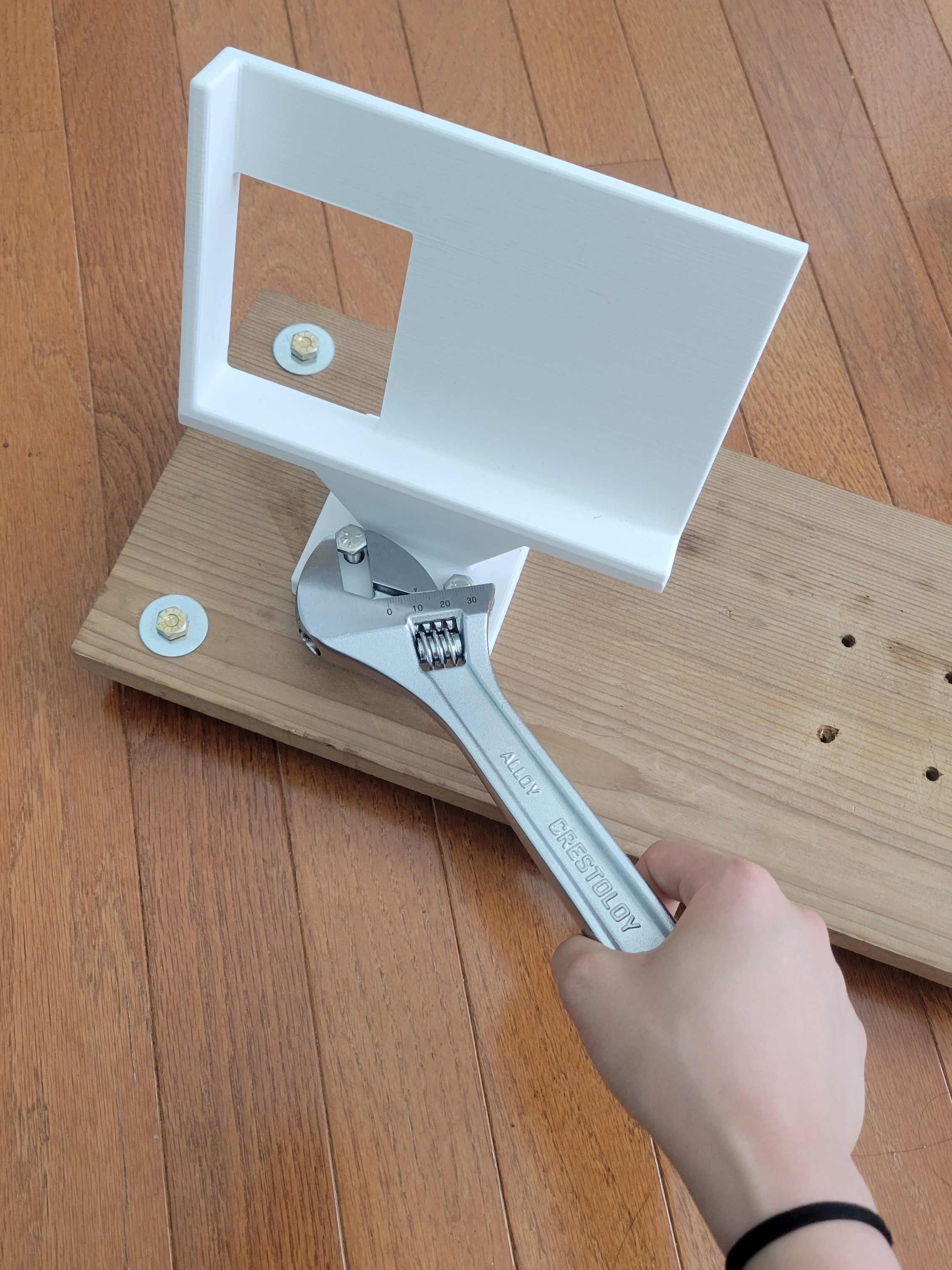
Attach to Intended Surface
Place the structure on top of the intended surface – a bridge railing, in our case. Hold the brackets below the surface, aligning the brackets' holes with those in the wood plank. Insert the four 1.5" partially-threaded screws through the washers, then the wood plank, then the brackets. Use hex nuts to secure.
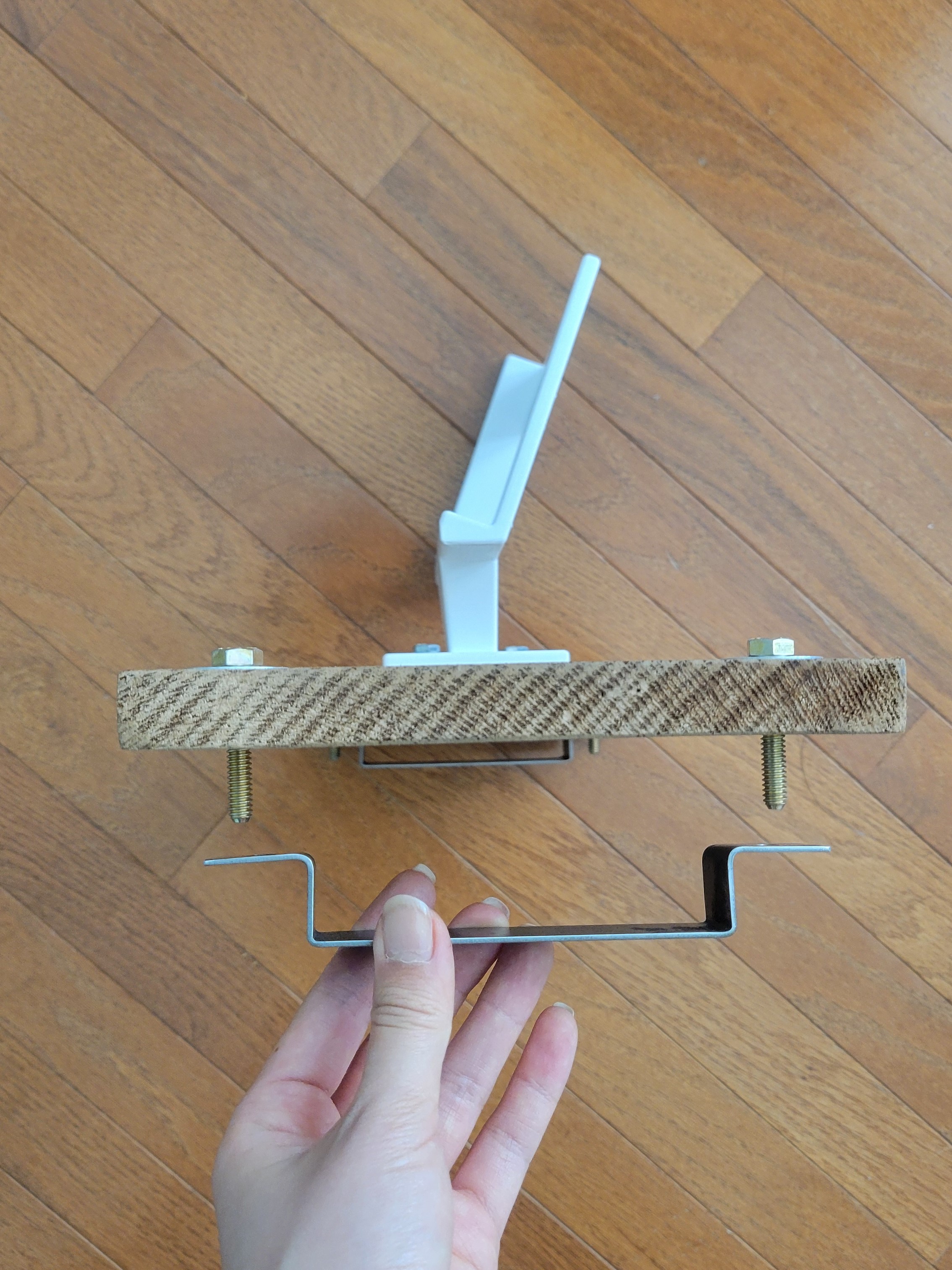
Attaching metal brackets
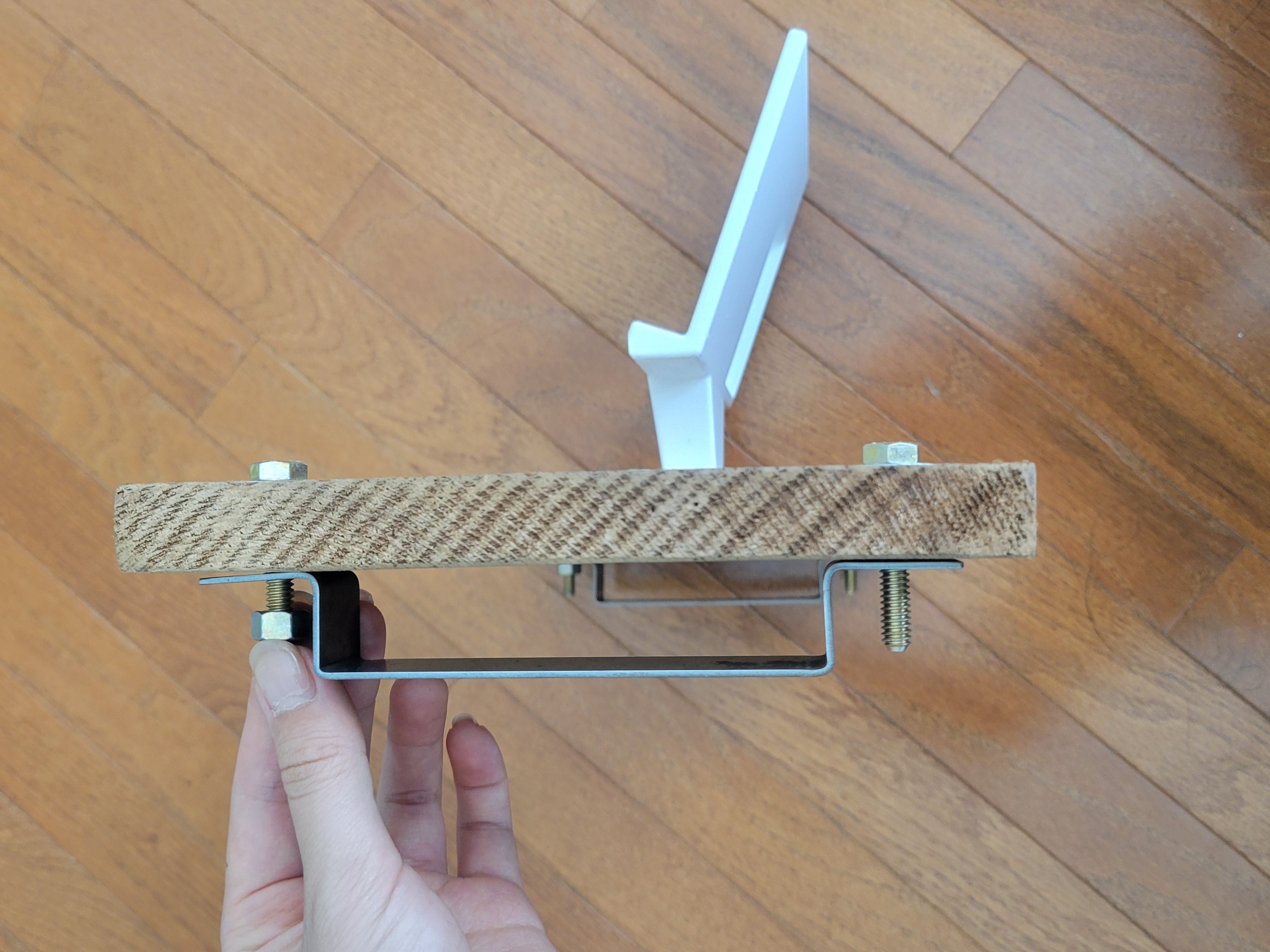
Securing brackets with hex nuts
Set Up Software
Download the MATLAB code for this software from this GitHub repository, and follow the instructions in the README.md file to set it up: https://github.com/lynna-deng/phone-stand-code
Create a Poster to Encourage Citizen Scientist Use
Create a poster to advertise the citizen scientist program to community members and explain the 3D reconstruction system's use. In the example poster, we make the process clear by outlining 3 steps and streamline the photo submission using a Google form available via QR code.
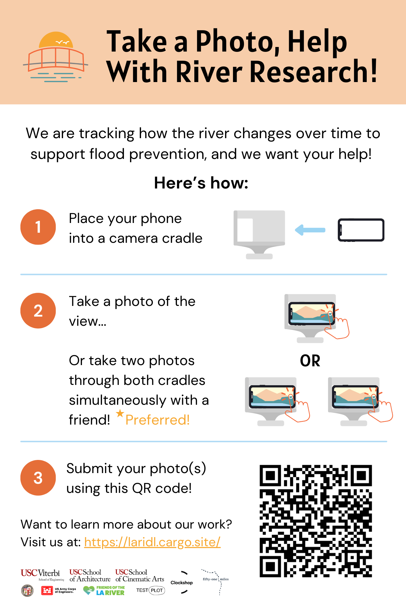
Example poster
Downloads
Begin Use!

Once fully configured and set up, you will be able to create 3D reconstructions!
Above is an example of the system in action. Two photographs were taken by a user from the two holders, then put through the MATLAB stereoCam_main.m file to generate a 3D reconstruction! A video of the reconstruction is attached so that you can see the full 3D scene.