Philips BT9290 Shaver (as Well As Others) Revival/refurbishment
by WWW_PLAWSKI_PL in Workshop > Repair
1713 Views, 5 Favorites, 0 Comments
Philips BT9290 Shaver (as Well As Others) Revival/refurbishment
)

We live in the days where more and more devices are made with non-user-serviceable prebuilt batteries. This approach can be somewhat justified with cell phones, where it is much easier to make watertight/dustproof if the case is glued/sealed together. When the battery dies on such a phone it is probably going to be already 2-3 years old and considering the technological advancements during that time, the majority of users will want a new phone anyways. Unfortunately, we see this approach also being applied to other devices, like this Philips BT9290 Shaver, although it's in no way unique, as the majority of all other manufacturers do exactly the same. Justified or not, I personally prefer to choose devices which have an easily accessible battery compartment, although it seems that in some categories of products this is a thing of the past. A little surprising considering the "right to repair" laws being put in place, where the batteries are something most likely to fail first, and thus should be easily replaceable.
So, how did I end up with this shaver? I won it in a contest for the most creative shave - just check out that "lizard" on the top of my head.
On the side note, the title states specifically Philips BT9290, but you will also find general tips, on the approach you should apply, taking apart any other similar shaver. Also, beside the text, you can view a video detailing the whole process, where it might be easier to see, how the certain components should be disassembled and then reassembled.
Supplies
- Shaver with dead batteries
- In the case of this Philips BT9290 - two AAA 750-800 mAh NiMH cells
Disassembly - Basics
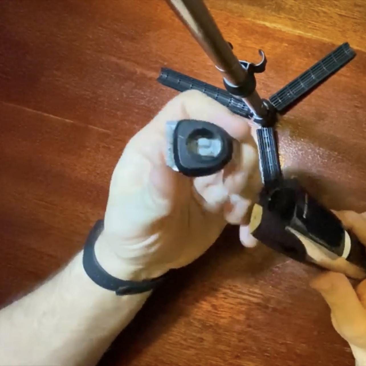

Let us start the disassembly by popping off the shaver head and looking if this exposes any screws underneath.
Seeing the two Philips head screws on top, we can proceede and remove them.
As this didn't do much, we need to establish what next should we try removing, and this is a bit of trial and error, as pulling too hard on some of the elements and we will break them.
It is therefore important to first try to slide the plastic elements (in case they have L-shapped hooks) before trying to pry (also gently) them up.
Top Panel Removal


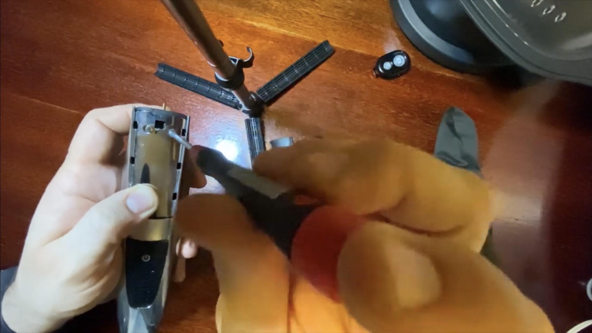


As sliding the panel didn't do much,we wedge our fingernails under the top edge of the panel and try puling it up. With a little force it snaps off, exposing another set of screws, which you should remove.
Now you can try sliding the metal cover in the direction of the power inlet socket, which will also allow for its easy removal.
Removal of the Internals From the Outer Shell

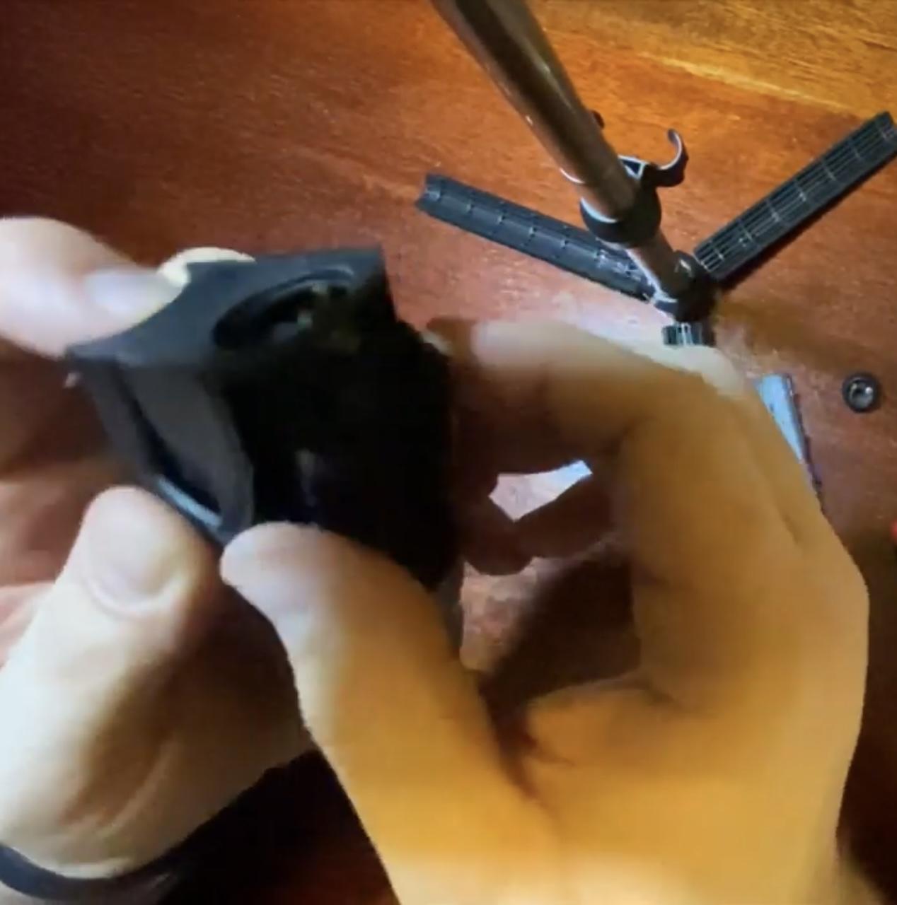

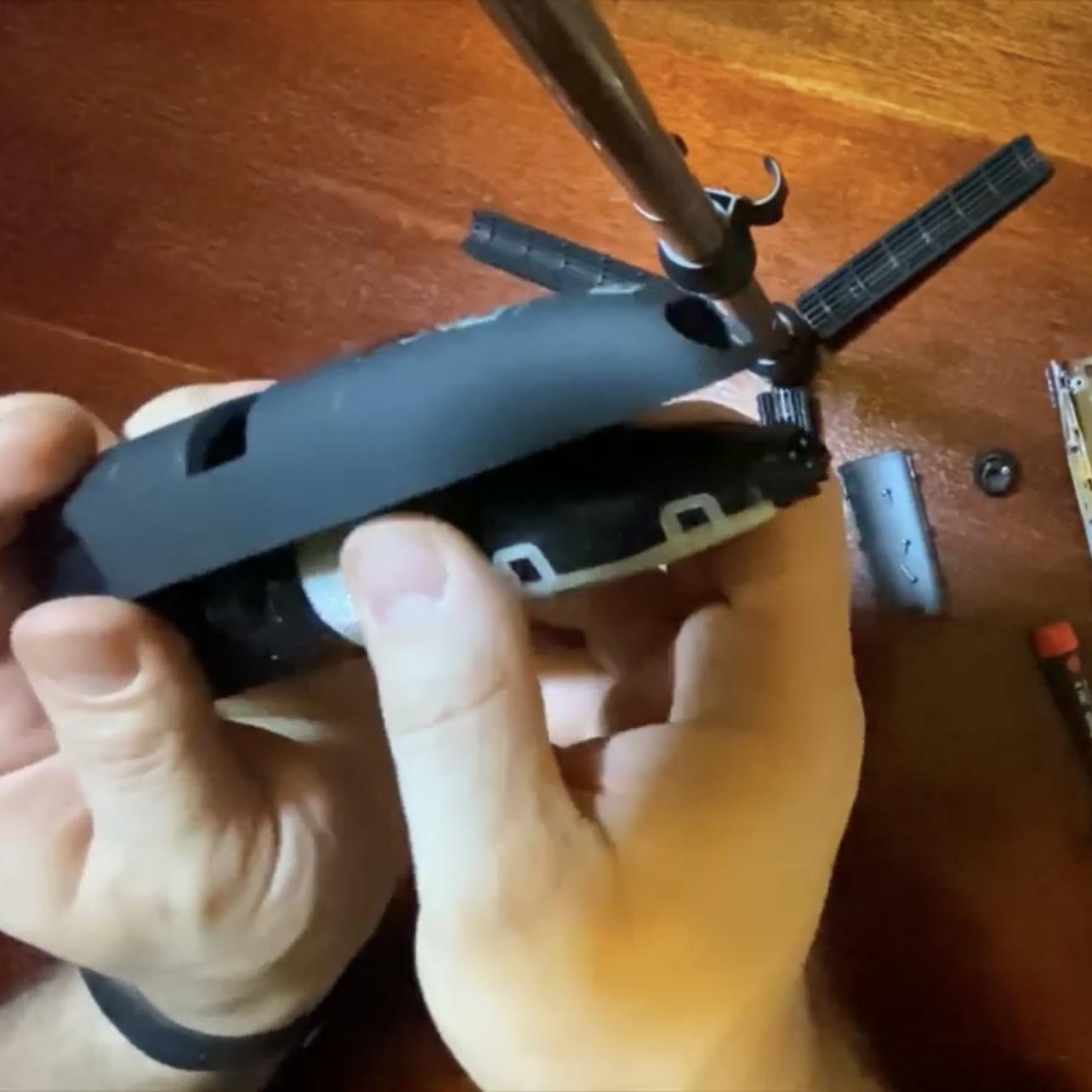
As we see another screw exposed, it should also be removed.
Now the more difficult bit, you need to push down on the guidenance laser and pry up the top of the internal subassembly and once it is half-way up, move to the bottom and push in the power supply socket, to release the entire subassembly.
Removal of the Guidenance Laser, Top Cover of the Internal Subassembly and Cutting Height Regulator
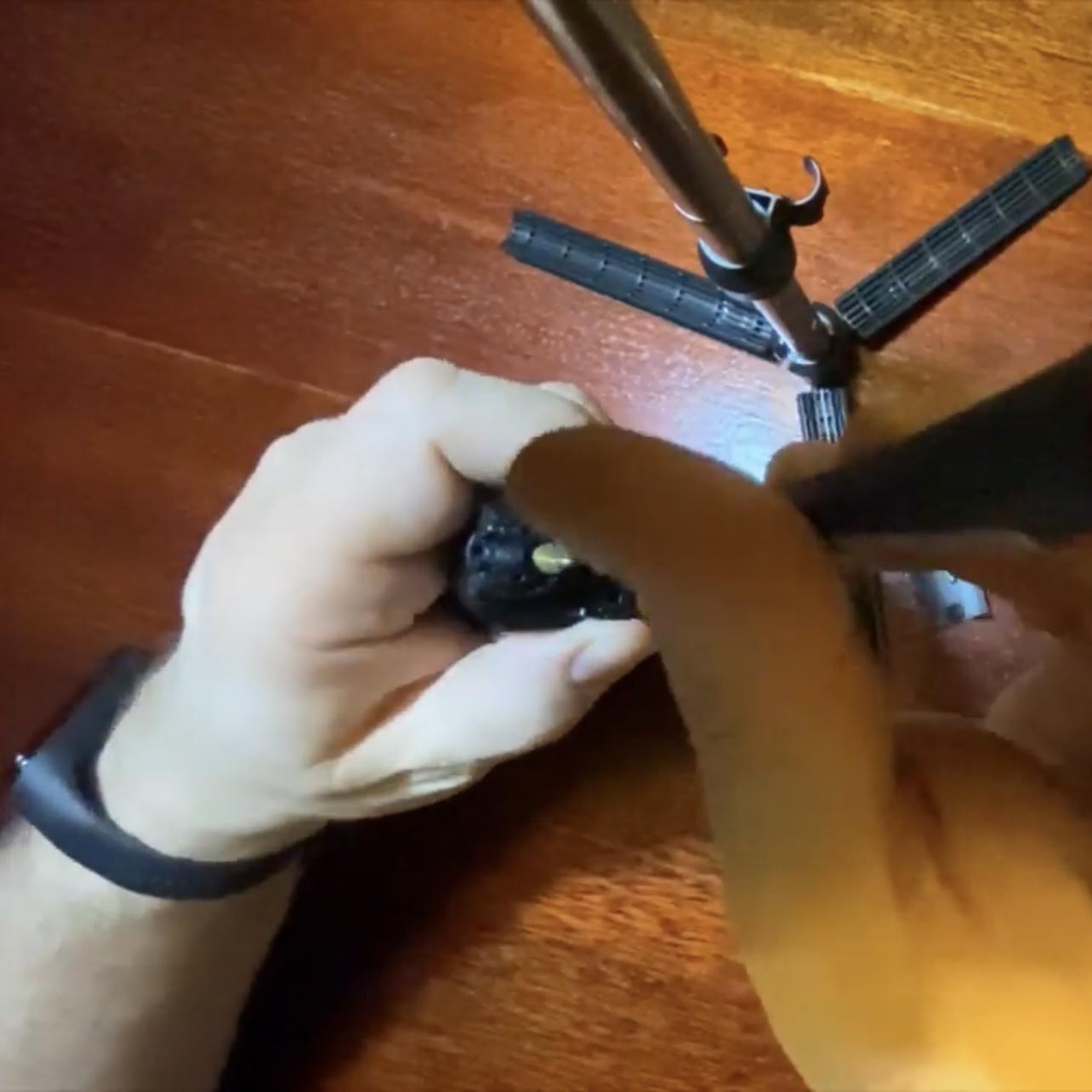

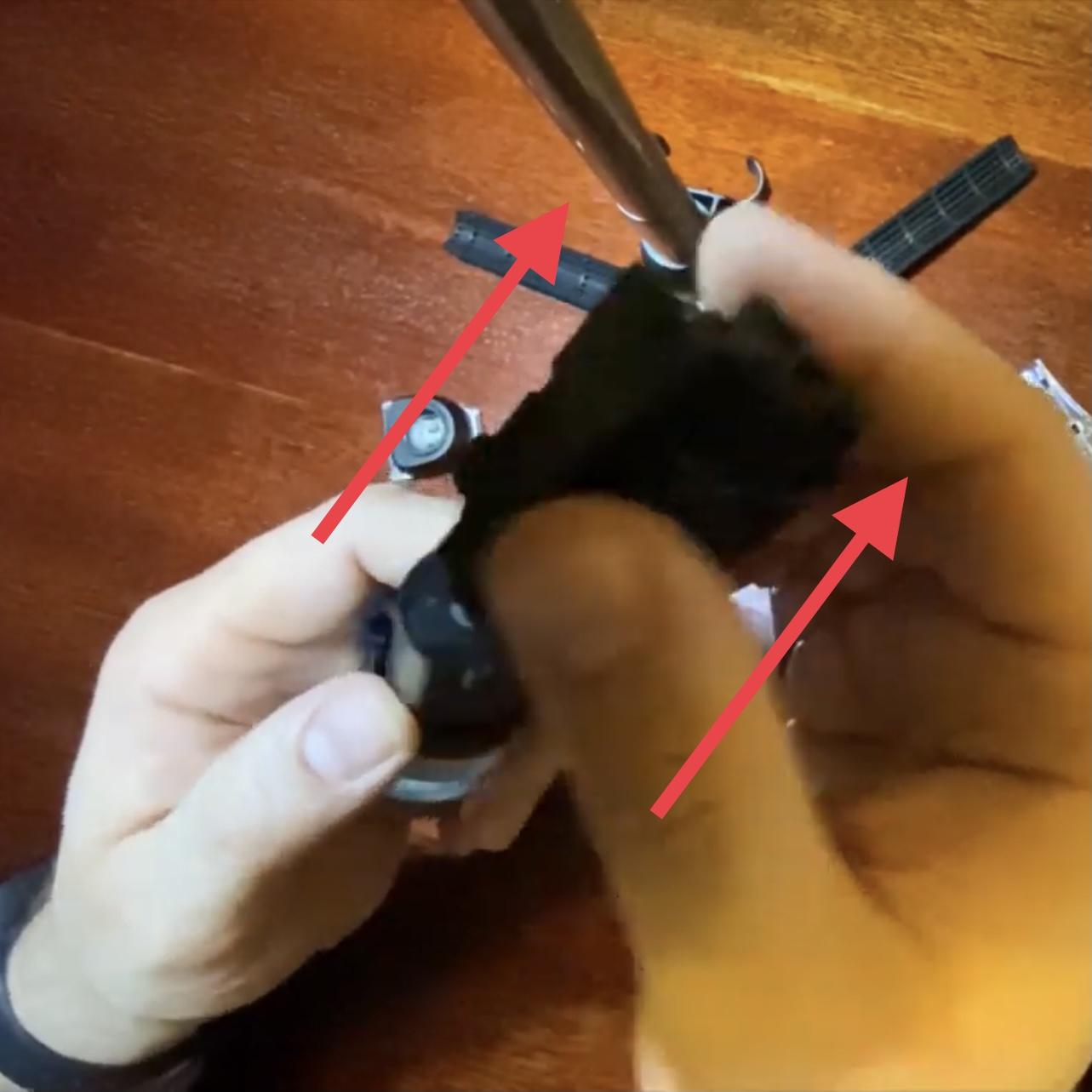
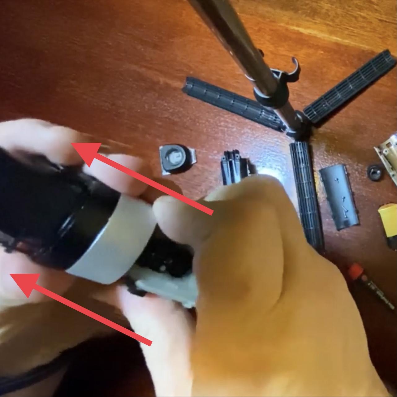
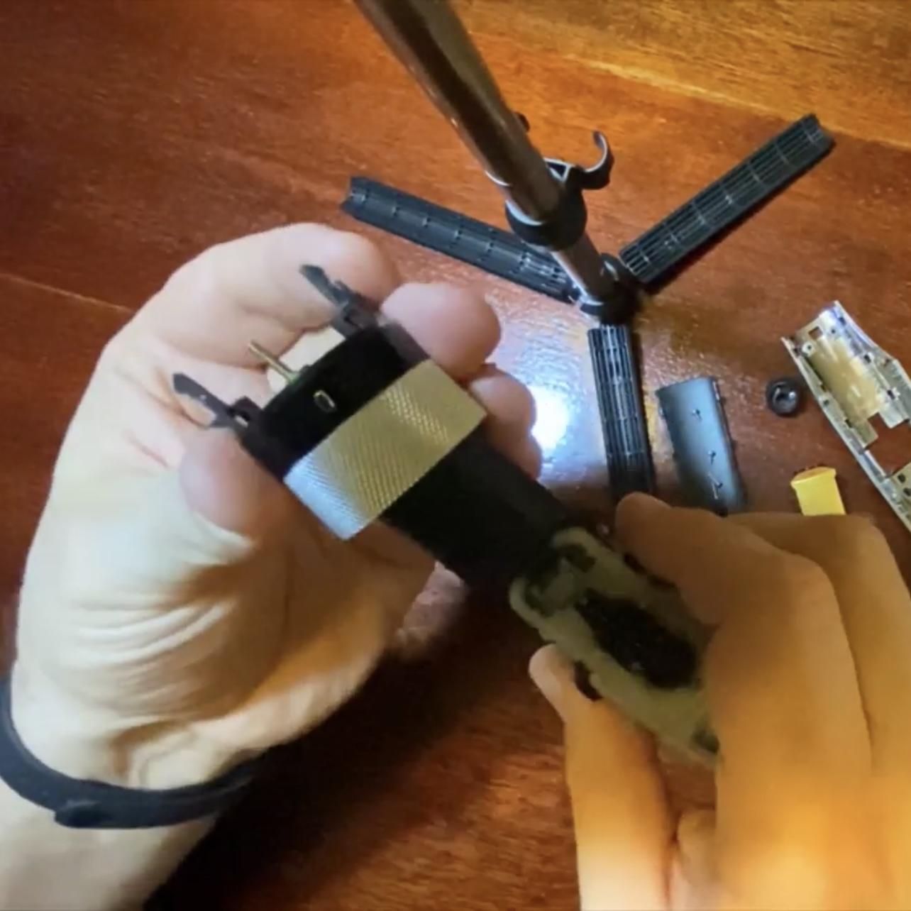
Unscrew any screws left on top of the internal subassembly, which are now exposed.
Remove the guidenance laser, which is a separate sub-assembly.
Slide off the top plastic cover, followed by the cutting height adjustment ring subassembly (try to remove it as a whole, so that later you won't have to worry how to put it back together)
PCB Disassembly

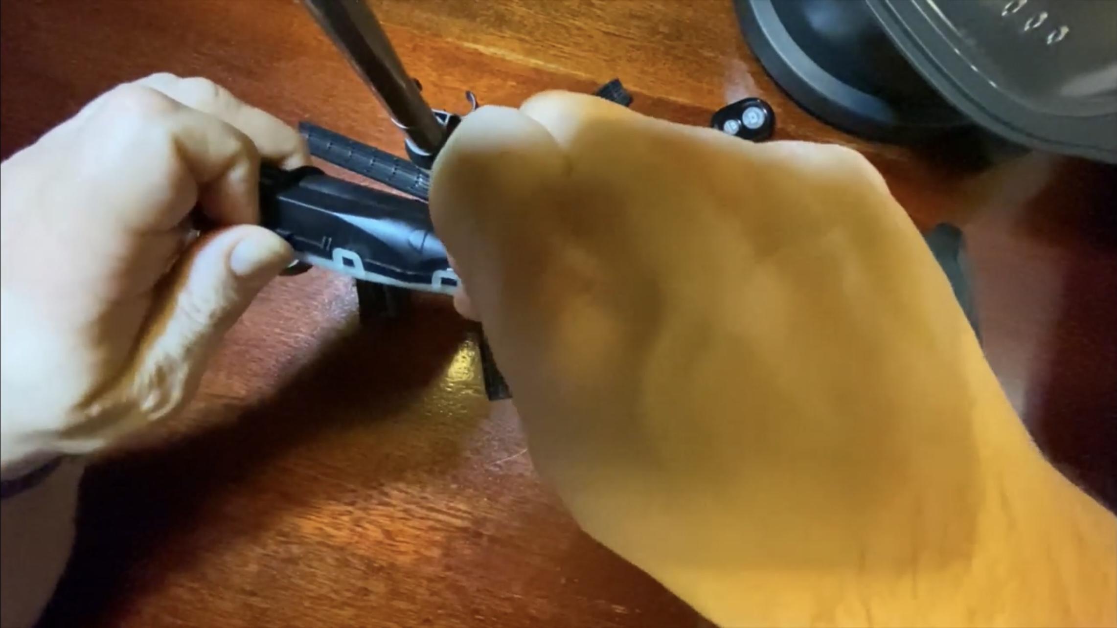
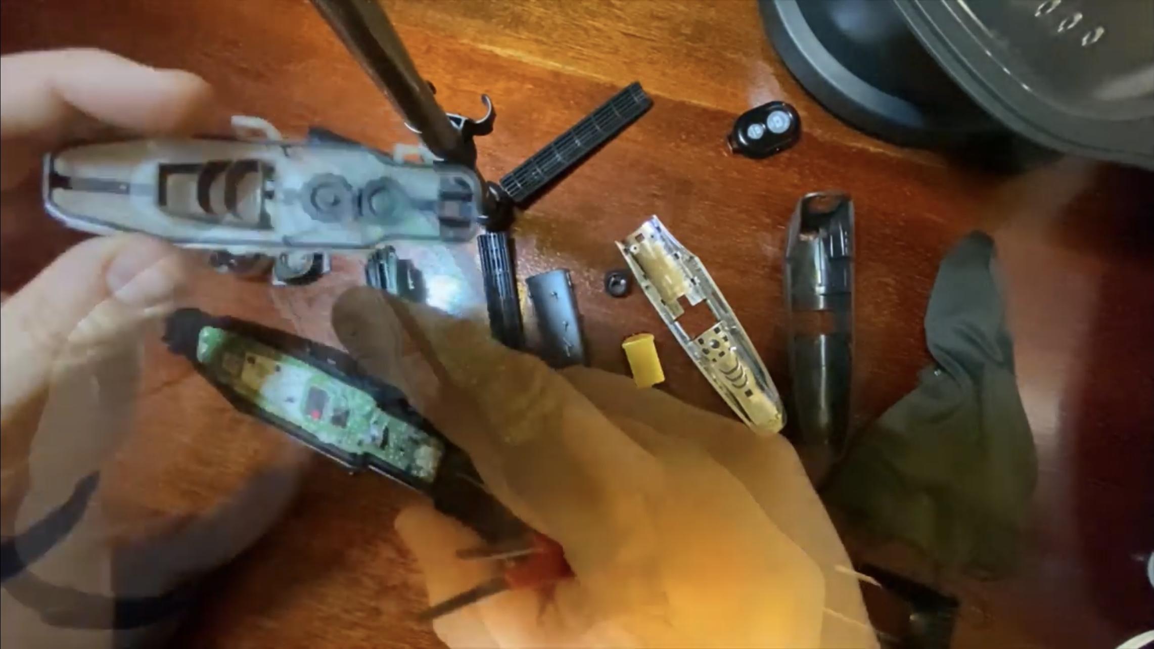


Here's another bit, which is a bit more difficult.
In order to get to the PCB board, you need to pry up the snaps on the sides of the white plastic cover, which should be done all at the same time, to get it removed. If you have any difficulty, you can use toothpicks etc. to keep these pried up, but be careful not to bend them too much, so that they won't break.
Once you have the cover off, the PCB surprisingly comes right out with a little prying, as it is just pressed in place.
Battery Removal and Selection of Replacements

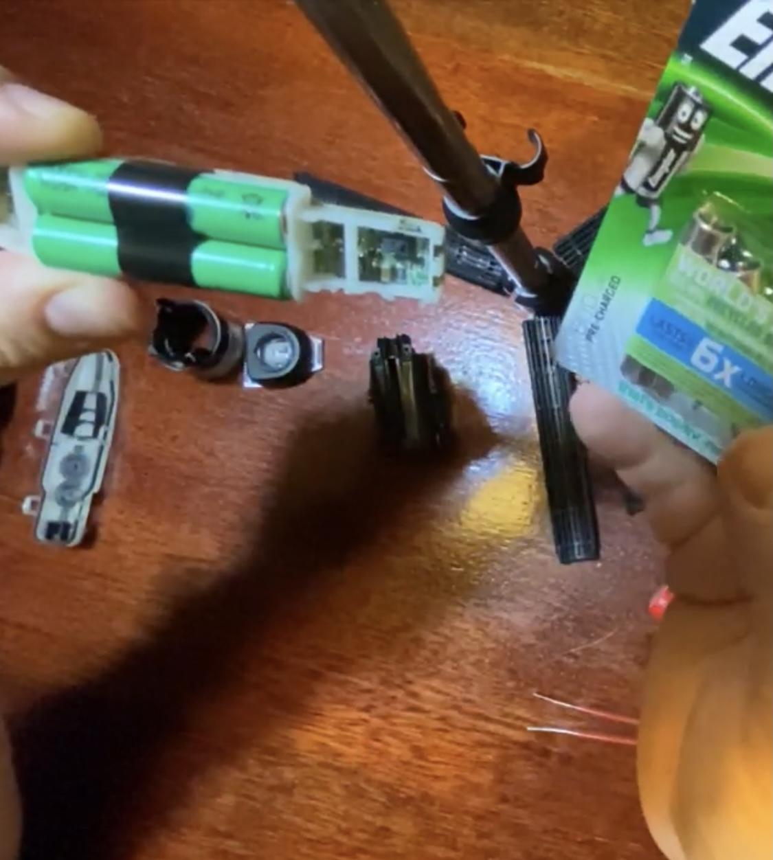


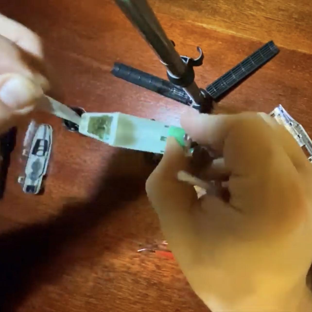

A quick glance on the original batteries. This unit uses 750 mAh AAA NiMH cells. When performing the replacement, it is important to use good quality cells of similar capacity and type. It might be tempting to install something of much higher capacity, but we don't know how the electronics exactly operate in the particular shaver and you don't want the batteries undercharged etc. as improper charging characteristic can quickly degrade their performance. You also want to use quality cells, as you probably don't want to repeat this entire process anytime soon.
Before performing the replacement it is a good idea to snap a picture, so that later you can recall the proper polarity, although in this case I later noticed it is marked on the PCB board.
Whilst examining the bateries I noticed another problem. They are not placed in a battery holder, but rather have spot welded terminals, which are then directly sottered to the PCB. Trying to unsotter them would cause another problem - how do we then connect the new "regular" AAA cells to the board? Considering this, I used the brute force approach. After removing the sticky tape holding the batteries (save this for later, as it will come in usefull) I pried them up, breaking off the spot weld.
Installing New Batteries
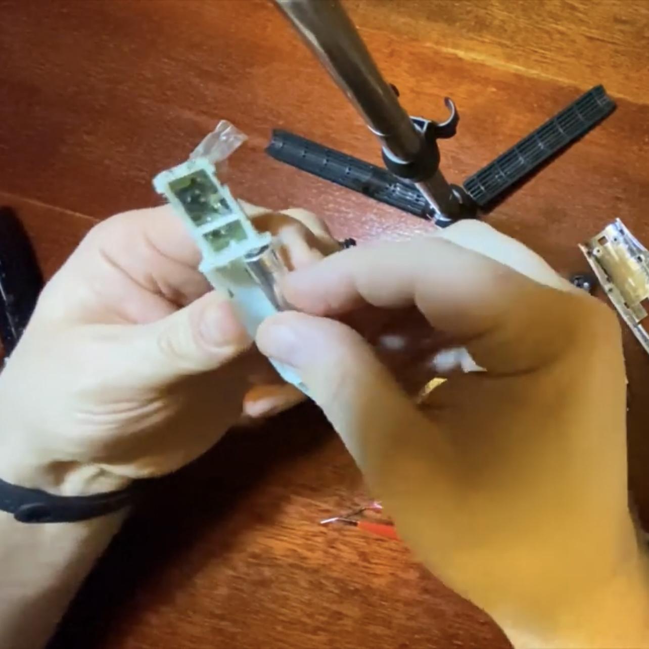
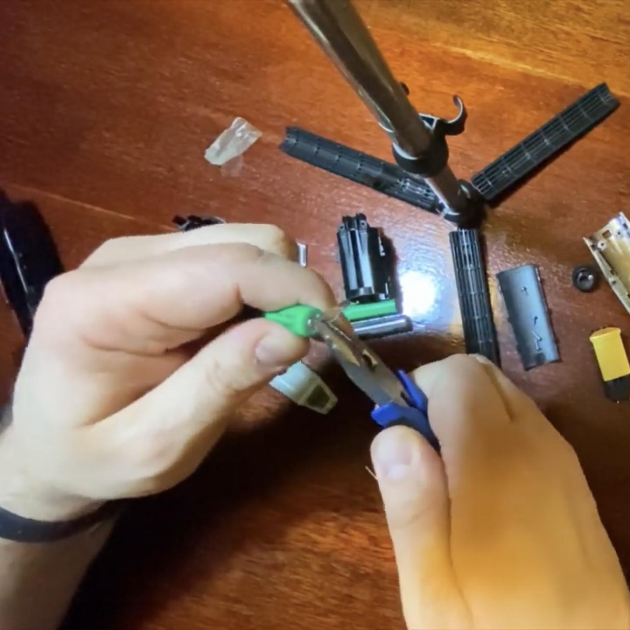
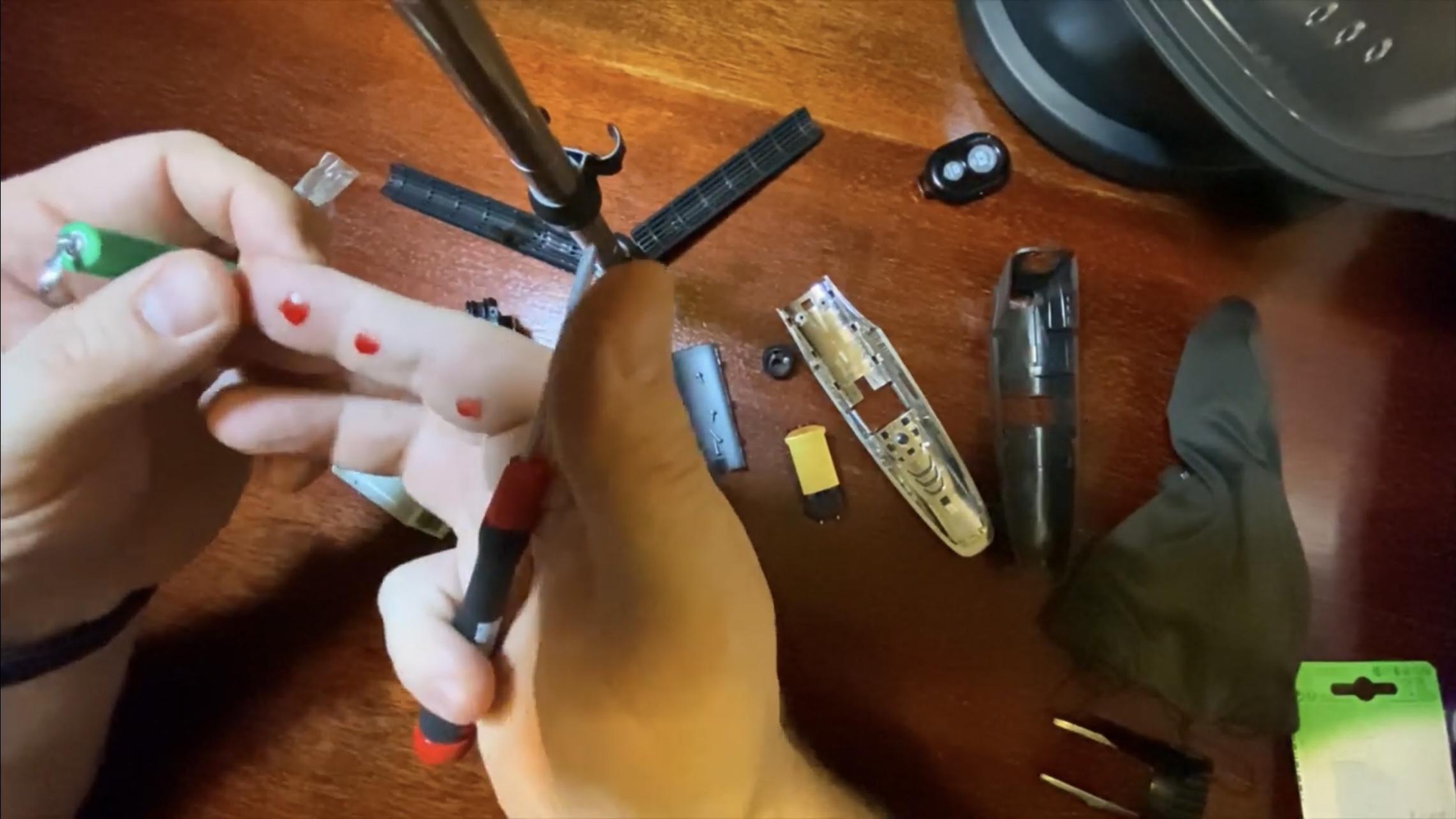

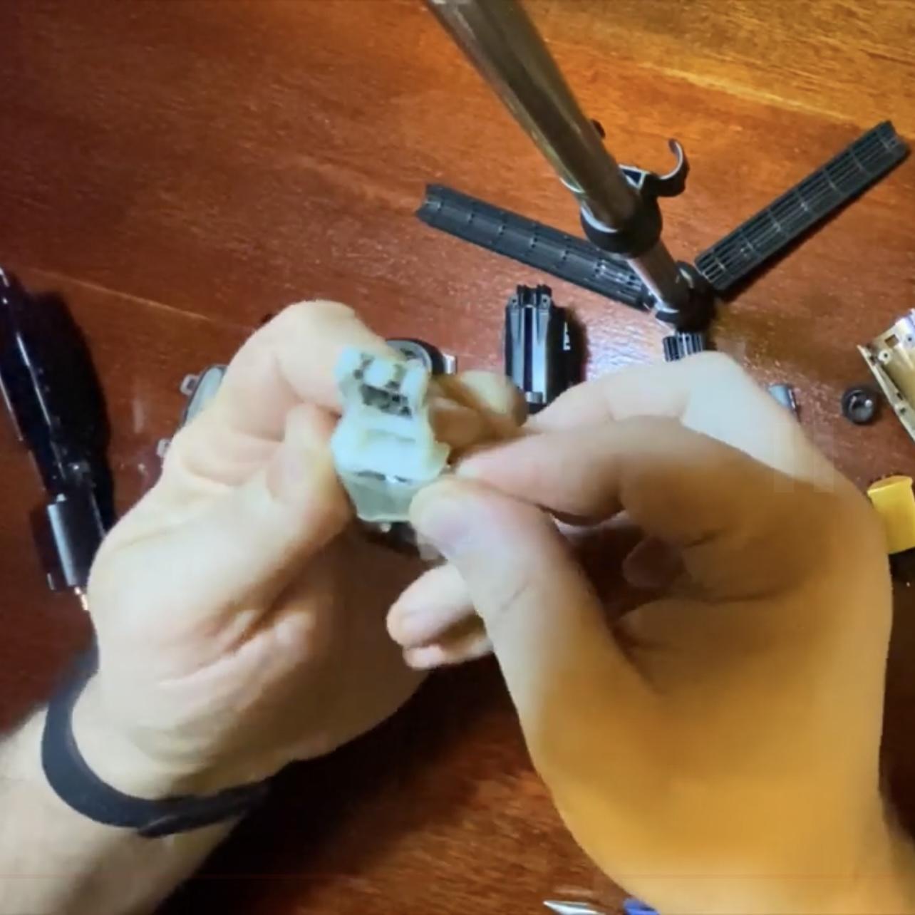
It is now time to put in the new cells - wedging them in, so that they make contact with the terminals, which were earlier spot welded to the original batteries. It is also important to assure contact of the two cells on the other end, and for this I used the original metal strip which was connecting (spot welded) the two removed cells, which I simply wedged in on the other end.
Be carefull ripping that off, as you can see in the picture I drew some blood from my finger, not even knowing when - this piece of metal is really sharp! Of course, you can also use some piece of wire for this purpose.
To finish off, I reused the original pieces of sticky tape to secure the cells in place ... now that's ultimate recyckling.
Reassembly of the Internal Subassembly
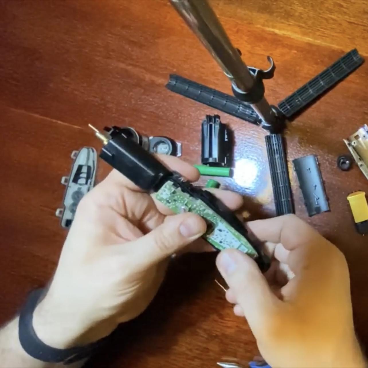


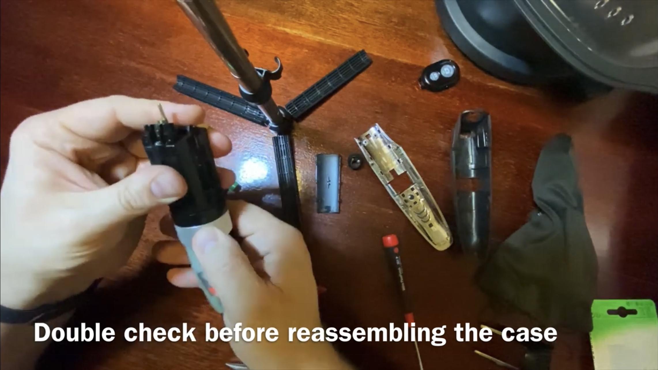
Reassemble the internal subassembly in the reverse order of the previous steps, snapping on the covers, cutting height adjustment rings, laser unit etc. and replacing all the screws.
Before trying to snap this into the external case, check if the elements operate correctly, are not seized, put on the right way etc.
Reassembly of the Whole Shaver


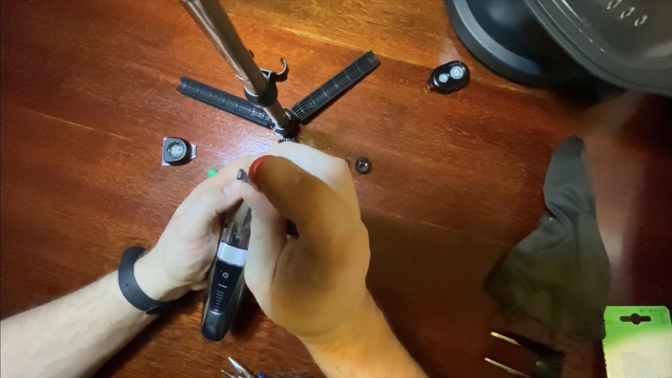


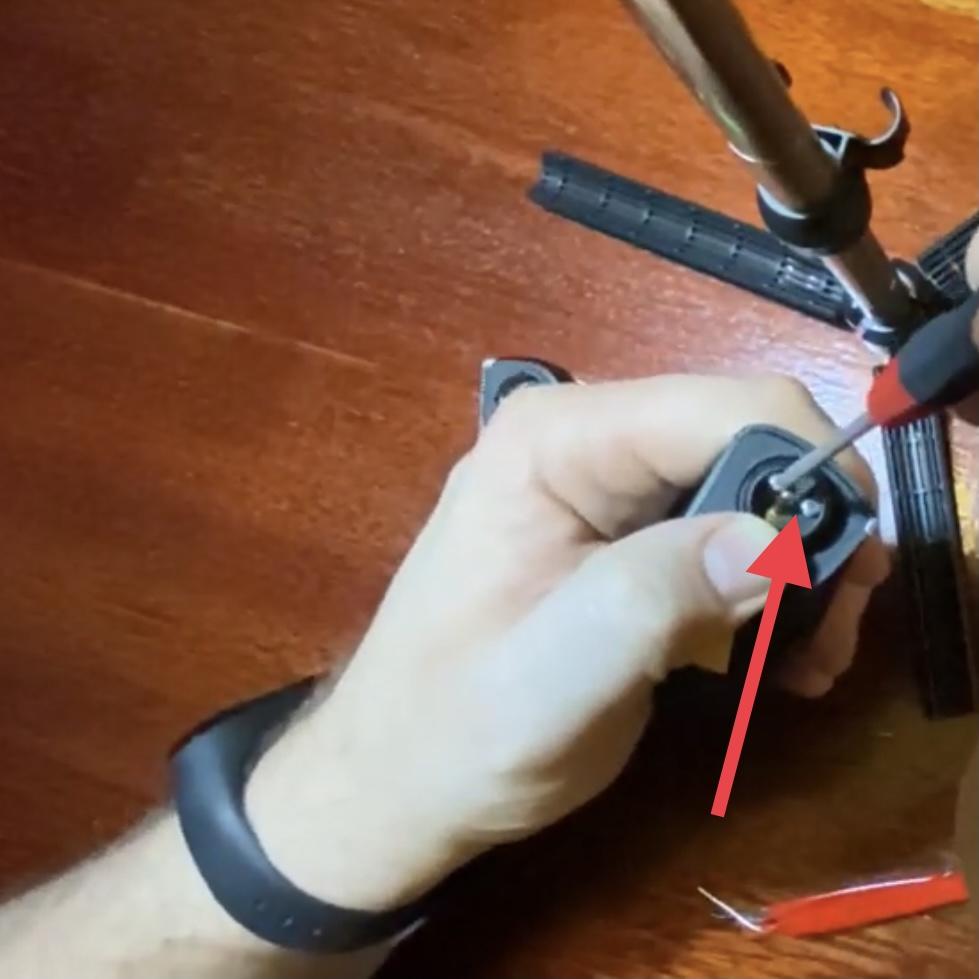

Now proceed with snapping in the internal assembly into the case, replacing all the necessary screws, covers etc., doing all the steps in reverse order of disassembly.
Congratulations!
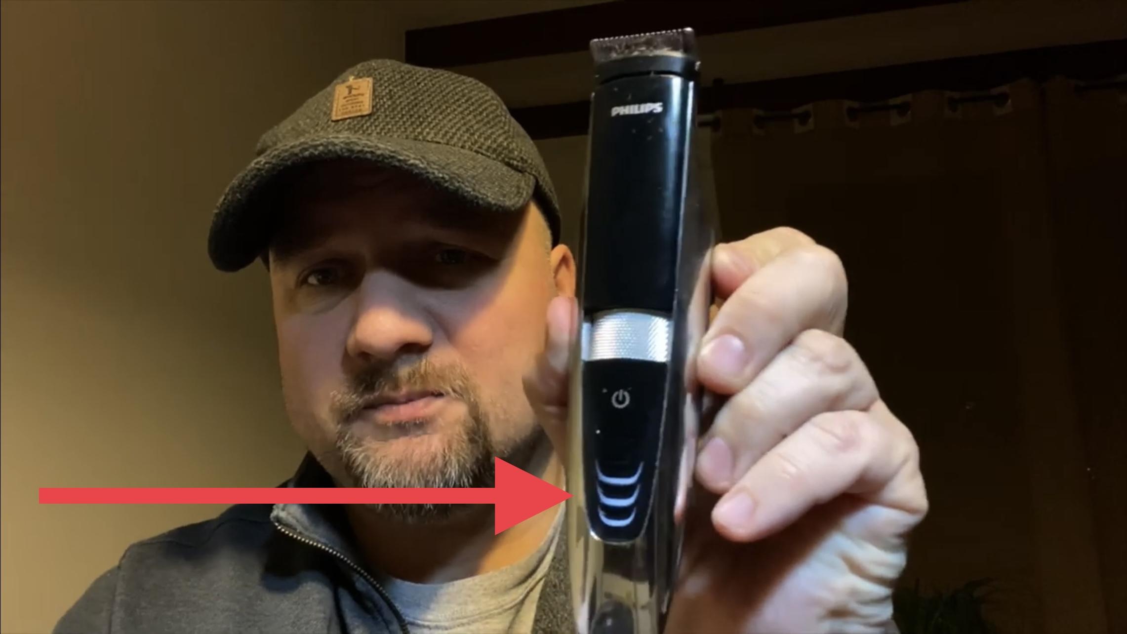
Congratulations!
You have fixed/refurbished your shaver for another few years of use. (Although at some time you might also need to look into the sharpness of the blades, but that's a topic for another Instructable!)