Penrose Wave Tile: a Mathematically Inspired 3D Design
by carterhoefling14 in Workshop > 3D Printing
3422 Views, 32 Favorites, 0 Comments
Penrose Wave Tile: a Mathematically Inspired 3D Design
**Eligible for Student Award Bev Facey Community High School Age: 15**
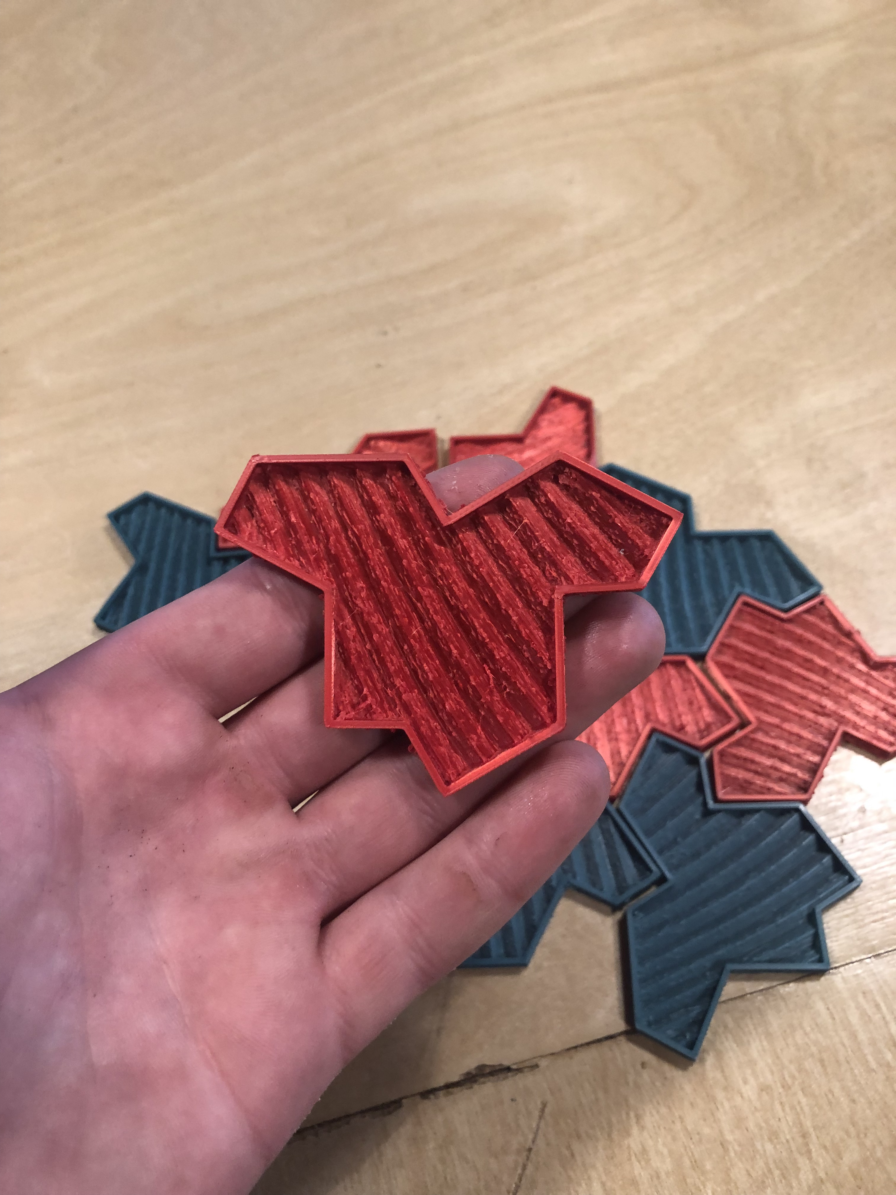
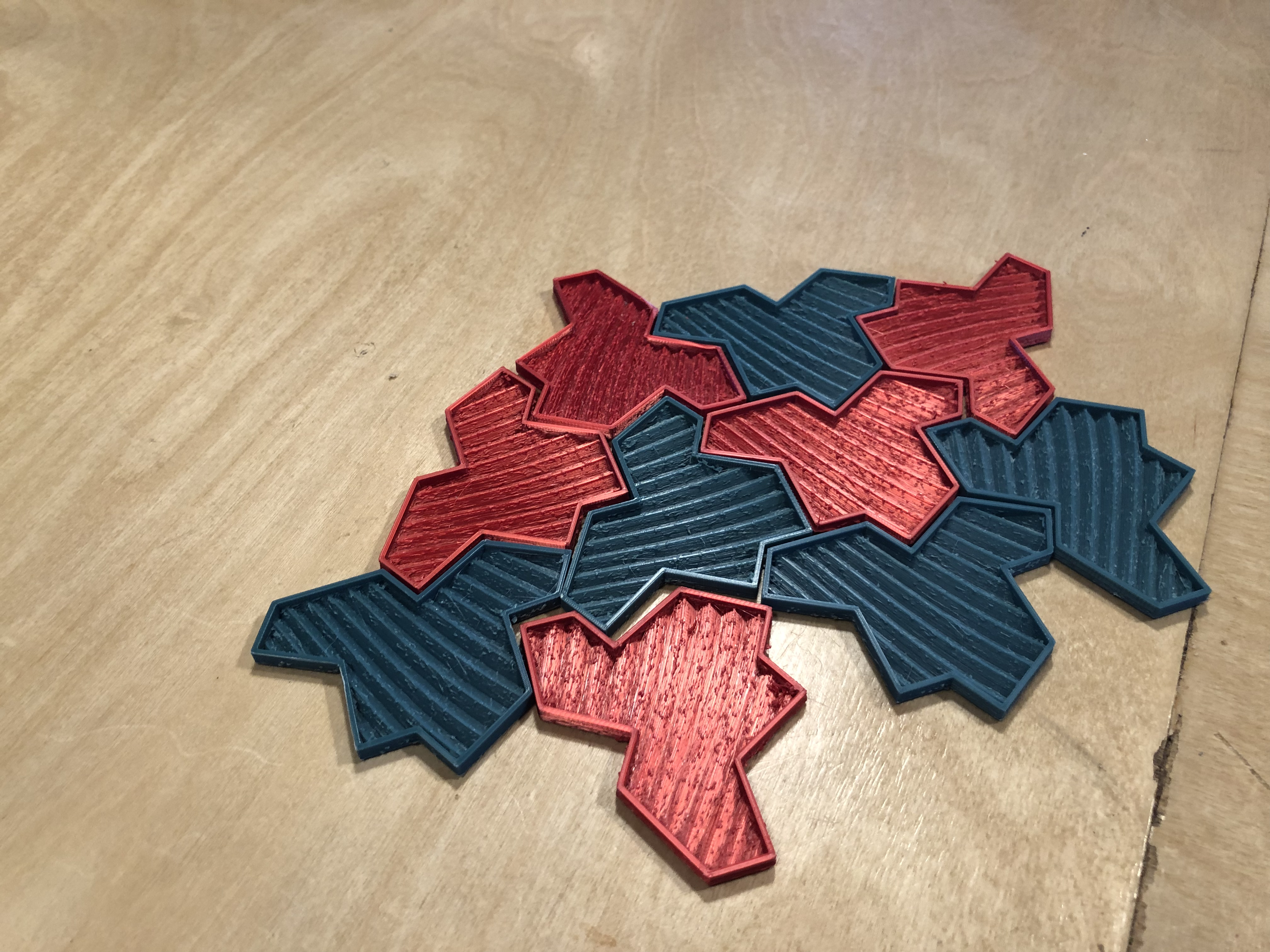
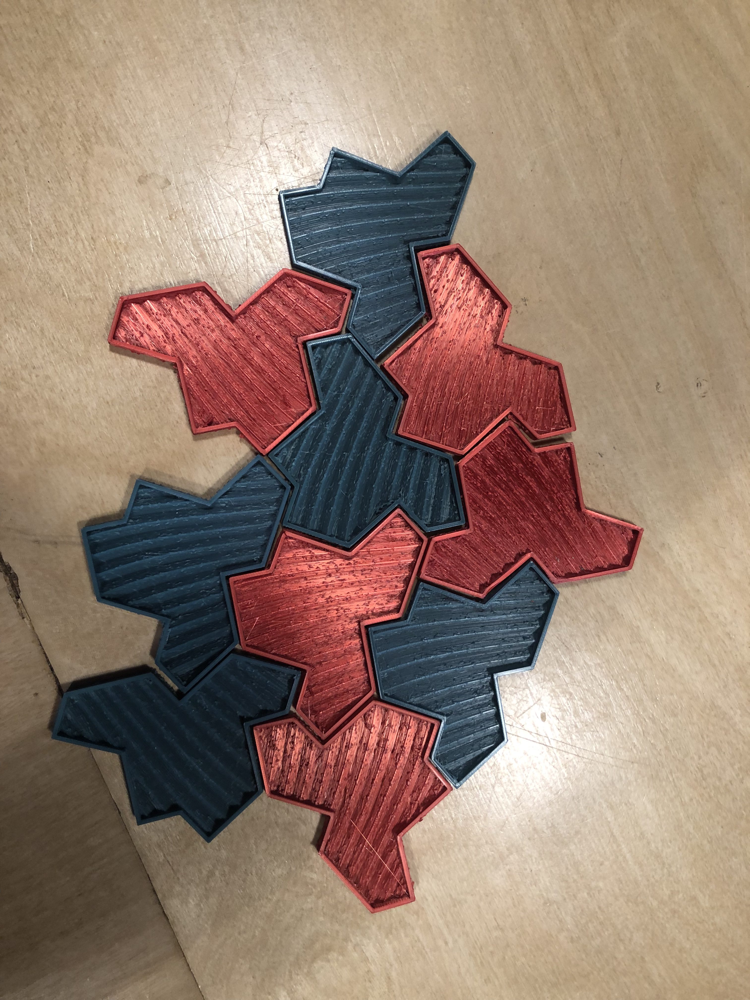
I’ve created a 3D-printed Penrose tile with an added wave pattern, designed in Fusion 360. The unique aspect of this tile lies in the intersection of two visually striking patterns: the timeless Penrose tiling and a fluid wave design. These two elements combine to form an infinite, non-repeating pattern, making the piece both mathematically intriguing and aesthetically captivating.
The Penrose tile is named after mathematician Roger Penrose, who discovered this form of tiling in the 1970s. Unlike traditional repeating tiling patterns (such as squares or hexagons), Penrose tiles create an aperiodic pattern—meaning they never repeat themselves exactly, no matter how large the surface. This concept is rooted in the mathematical study of quasicrystals and symmetry, representing a breakthrough in both geometry and material science. Penrose tiling has since found applications in areas ranging from art and design to theoretical physics, where it is used to model quasicrystals, a unique form of solid matter
Supplies
Any 3D Printer
Fusion 360
Creating Penrose Pattern in Sketch
Find a Penrose Tile Pattern:
- Search for a high-quality Penrose pattern image or vector file (such as a .png, .jpg, or .svg). For best results, choose a simple version of the pattern with clear, distinct edges.
- Download the file to your computer.
Open Fusion 360 and Import the Pattern as a Canvas:
- Open Fusion 360 and start a new design.
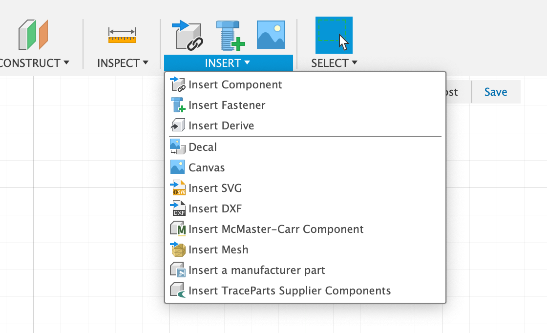
- Go to Insert > Canvas, and select the Penrose pattern image from your files.
- Position the canvas on one of the planes (usually the X-Y plane).
- Use the Scale tool to adjust the size of the canvas. The scale is up to user preference, but for this project, I recommend scaling it to 100mm (10cm) for a manageable and printable size.
Start a New Sketch Over the Canvas:
- With the canvas now imported and scaled, create a new sketch by selecting Create Sketch from the toolbar and choosing the same plane where the canvas was placed.
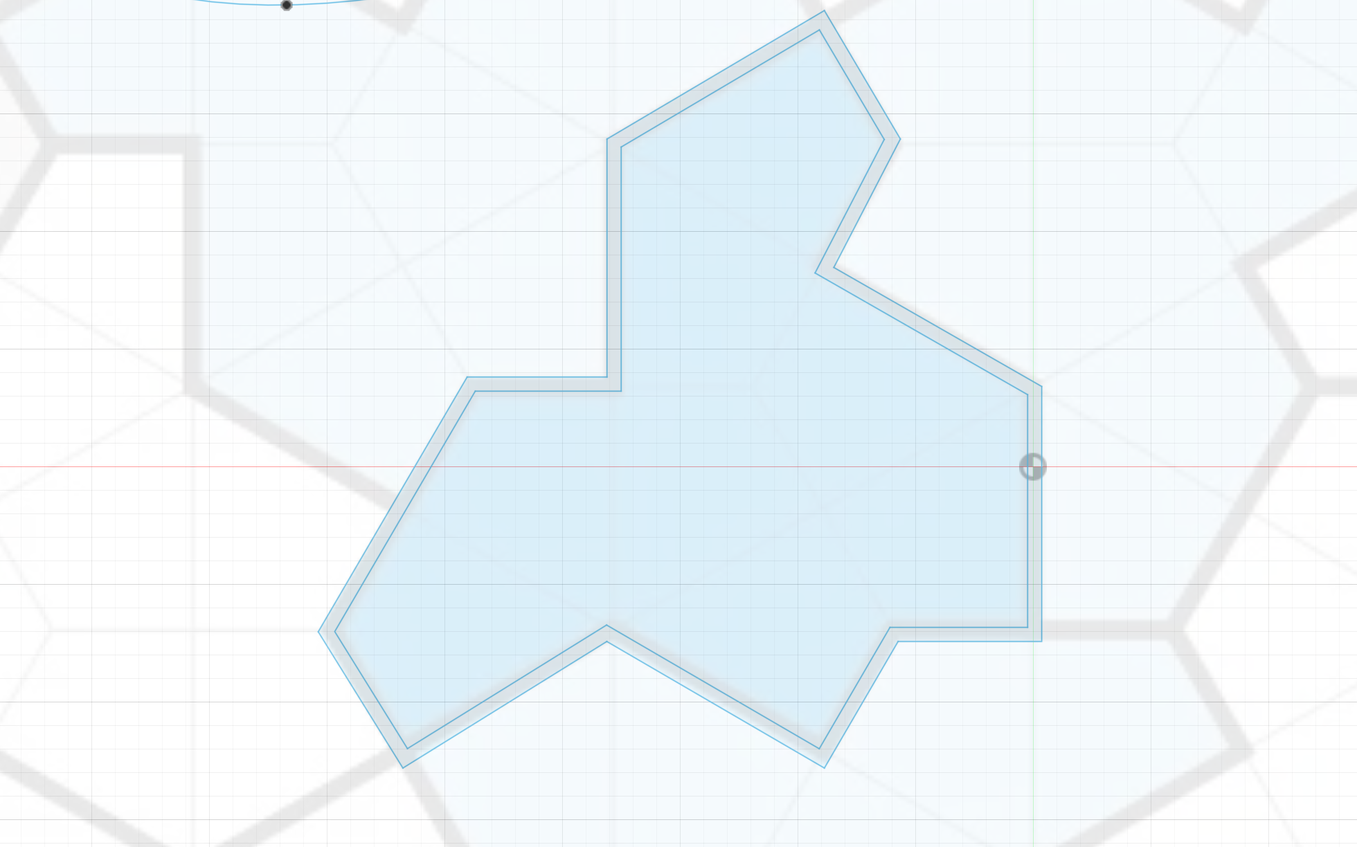
Trace the Penrose Pattern:
- Use the Line and Arc tools to carefully trace the Penrose pattern. Follow the edges and angles of the canvas, making sure the lines connect cleanly at the vertices.
- Use the Snap tool to ensure precision and consistency in your sketch.
- If applicable, use the Mirror tool to replicate symmetrical parts of the pattern, speeding up the tracing process.
Create an Offset for the Wall:
- Once the Penrose pattern is fully traced, select the entire traced sketch.
- Use the Offset tool (found in the Modify menu) to create an offset of the pattern toward the inside, leaving enough space to form a wall between the outer edge of the tile and the inner wave pattern.
- For this project, try an offset of around 2-5mm, depending on the thickness you want for the wall. You can adjust this based on your design preference.
Finish the Sketch:
- Once the offset is in place, hide or delete the canvas to reveal a clean, precise sketch of the Penrose pattern with the inner offset.
- Double-check your lines and angles to ensure they are accurate and that the pattern is ready for the next step.
Creating Wave Rails/Path
Enable the Original Penrose Sketch:
- In Fusion 360, ensure your original Penrose pattern sketch is visible. If it's not, go to the Browser panel on the left, expand the Sketches section, and click the eye icon to make it visible.
Create a New Sketch on the Same X-Y Plane:
- With the Penrose sketch enabled, create a new sketch on the same X-Y plane by selecting Create Sketch again. This will allow you to overlay new elements on top of your original design.
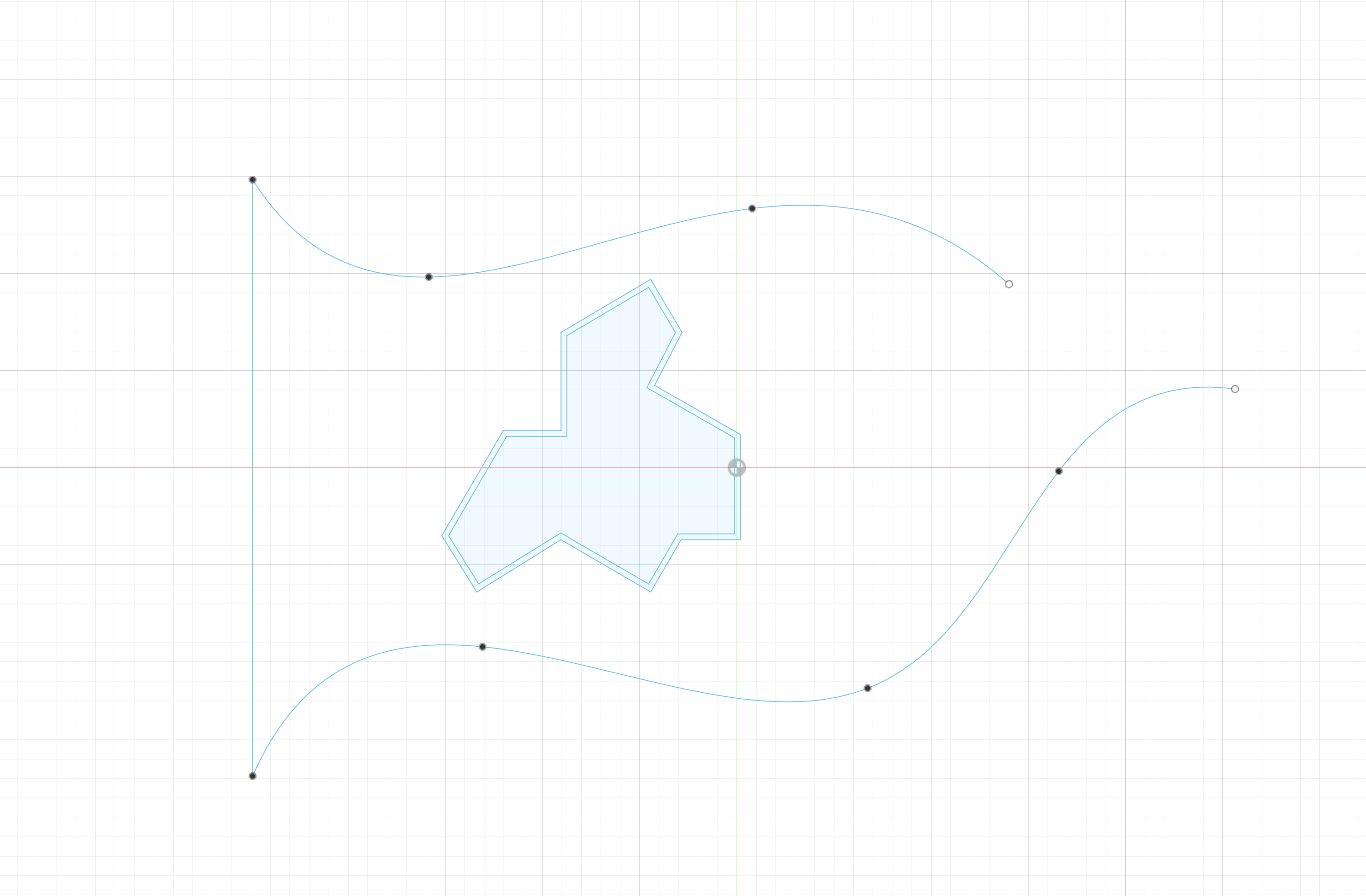
Use the Spline Tool to Draw Two Curvy Paths:
- In the new sketch, select the Spline tool from the toolbar.
- Begin by drawing two curvy, organic paths that will flow across the tile. These curves can follow any form you'd like but should work well with the overall Penrose design.
- Experiment with adjusting the control points to refine the curves' smoothness and flow.
Join the Paths with a Horizontal Line:
- On the far left side of the sketch, use the Line tool to draw a horizontal line that connects the two spline paths. This line will serve as a boundary or connecting element for the design.
Finish the Sketch:
- Once your two curvy paths and the connecting line are complete, review the sketch to ensure everything is smooth and aligned.
Creating Wave Sketch
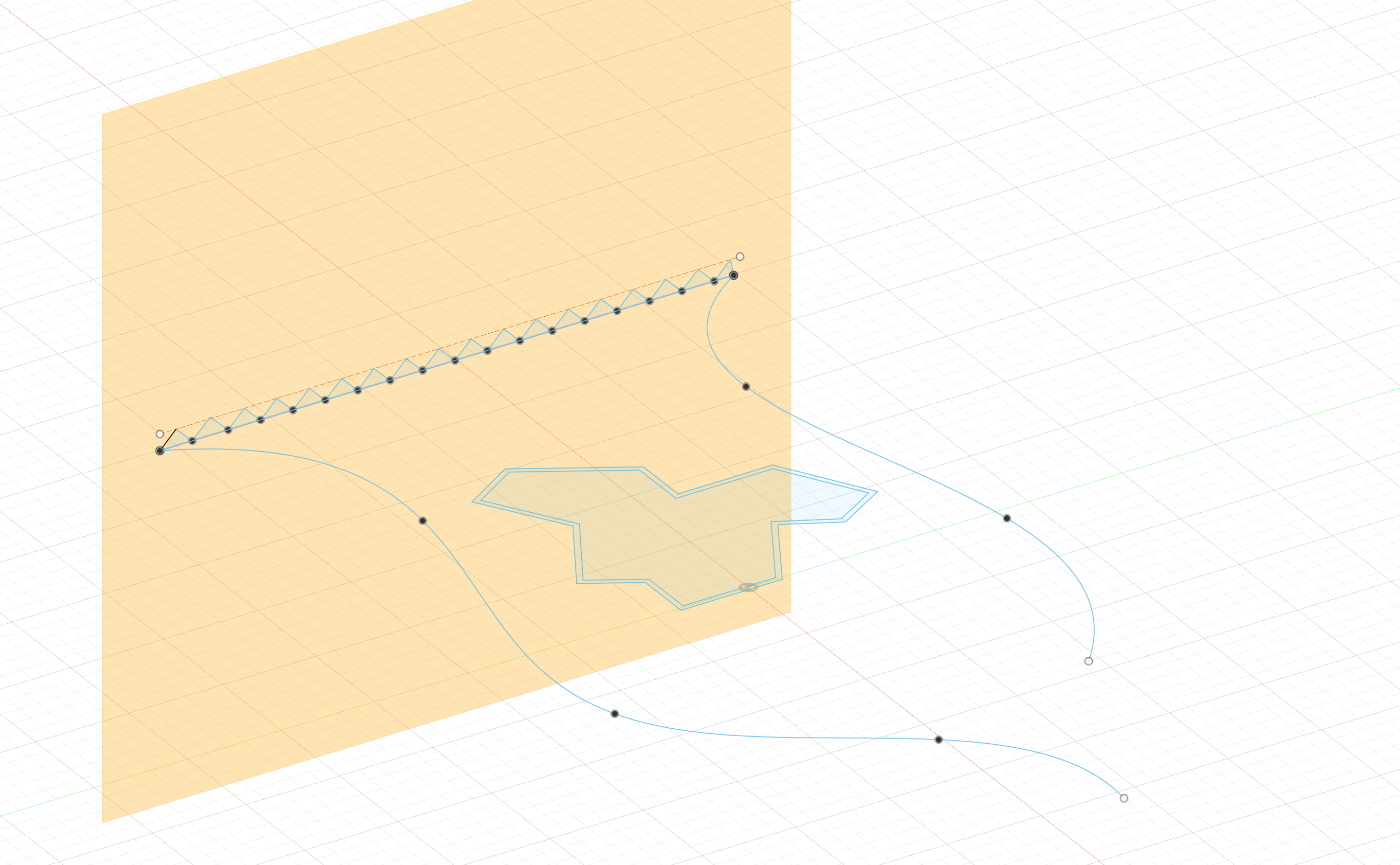
Create a Perpendicular Construction Plane:
- Using the straight horizontal line from the previous sketch as a reference, create a construction plane that is perpendicular to it.
- To do this, go to Construct > Plane at Angle, select the horizontal line, and set the angle to 90 degrees, ensuring the two lines remain perpendicular.
Start a New Sketch on the Construction Plane:
- With the new construction plane in place, create a new sketch by selecting Create Sketch and choosing the perpendicular construction plane you just made.
Project the Straight Line onto the New Sketch:
- To bring the straight line from the previous sketch into this new sketch, use the Project tool.
- Select Project/Include from the toolbar and click the horizontal line from the original sketch to project it onto your new sketch on the construction plane.
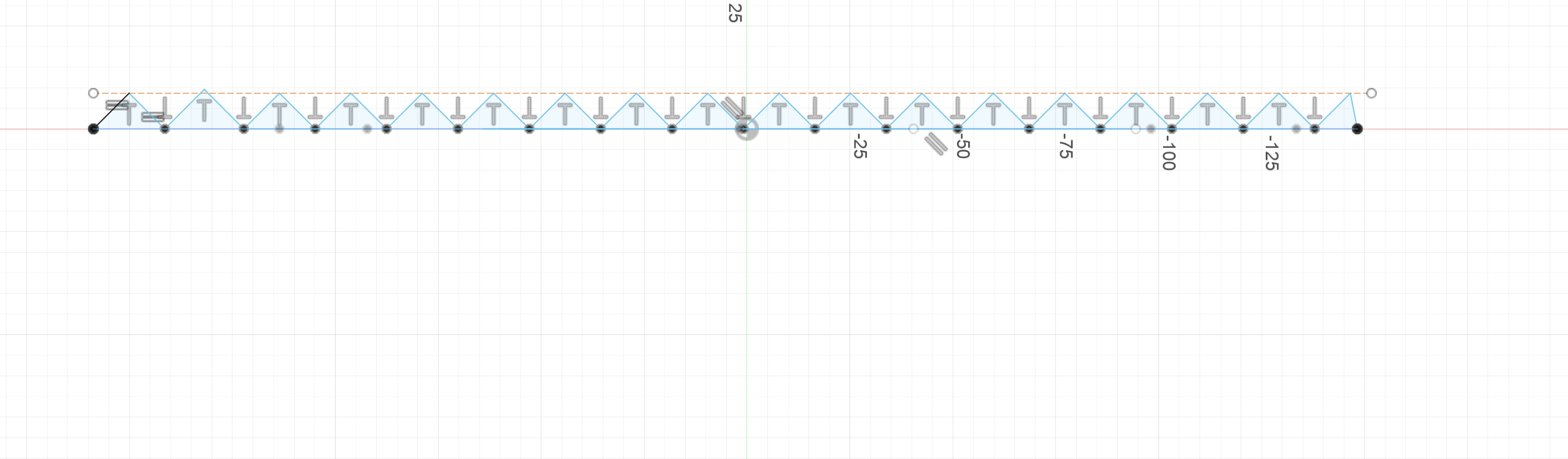
Create Equal Triangles Along the Projected Line:
- With the straight line now projected, use the Line tool to draw equal-sized triangles along the line.
- Ensure the triangles are evenly spaced and aligned, using Fusion 360's Sketch Dimension and Equal constraints to maintain equal side lengths and proper spacing.
Finish the Sketch:
- Once the triangles are in place, review the sketch to ensure symmetry and equal proportions.
- These equal triangles will introduce a geometric pattern that interacts with the wave and Penrose elements, adding complexity to the design.
Sweeping Sketch
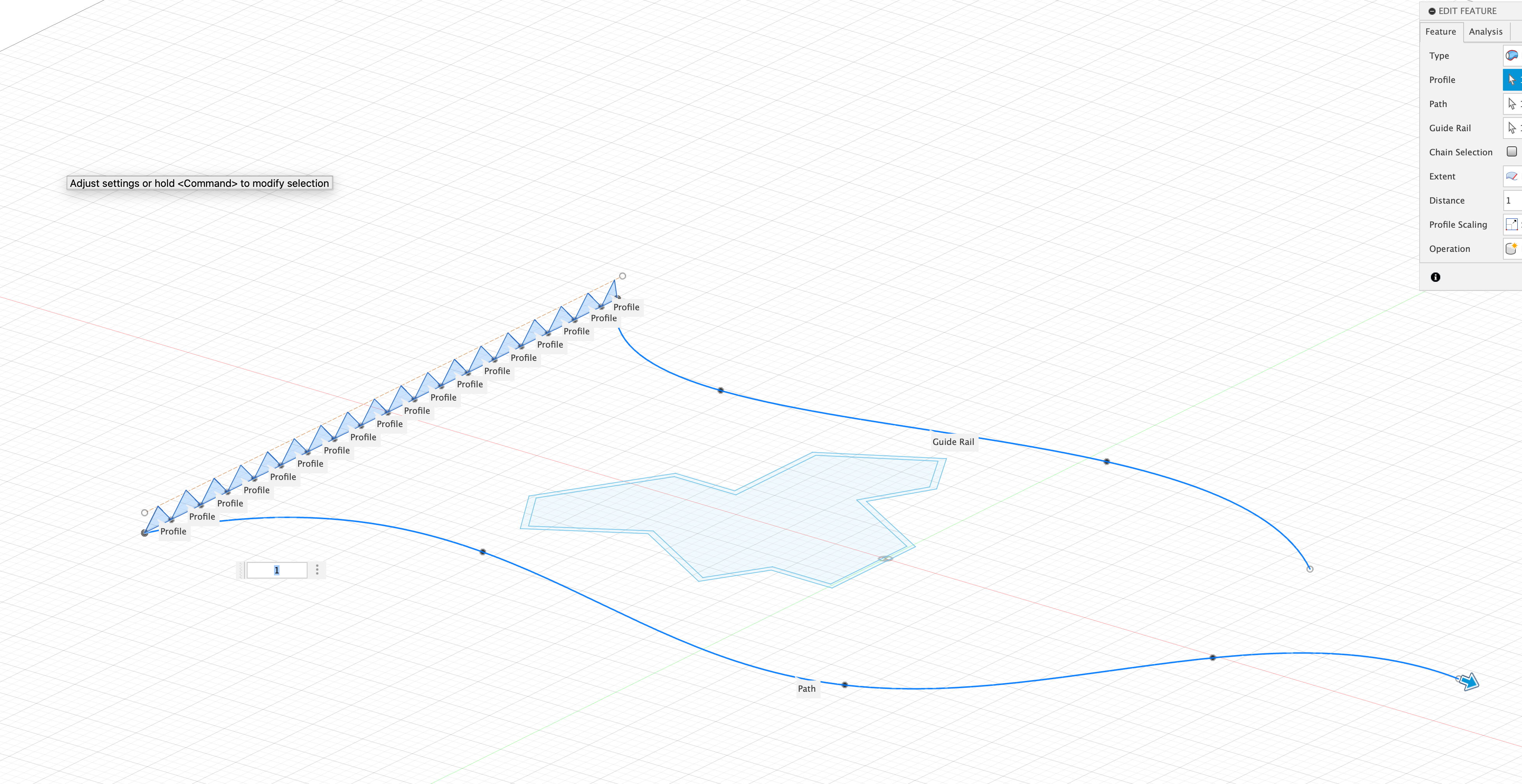
Select the Sweep Tool:
- With your triangle sketch complete, navigate to the Create menu and select Sweep.
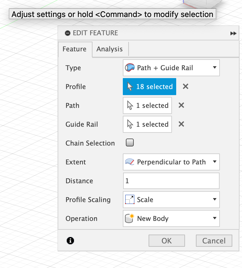
Set the Sweep Type to "Path" and "Guide Rail":
- In the sweep dialog box, change the sweep type to Path and Guide Rail.
- Select one of the curvy lines from your earlier sketch as the Path.
- Then, choose the other curvy line as the Guide Rail.
Ensure Perpendicular to Path is Enabled:
- In the sweep settings, make sure that Perpendicular to Path is selected. This keeps the triangles aligned perpendicular to the sweep direction as they move along the path.
If Needed, Change to Full Extents:
- If the sweep doesn’t work as expected with the current settings, change the option to Full Extents to ensure the entire triangle profile sweeps across the full length of the curves.
Complete the Sweep:
- Once the settings are configured correctly, confirm the operation. The triangles will now sweep along the curvy path, guided by the second curve, creating a flowing geometric extrusion that complements the overall design.
Creating Shape (Almost There!!!)
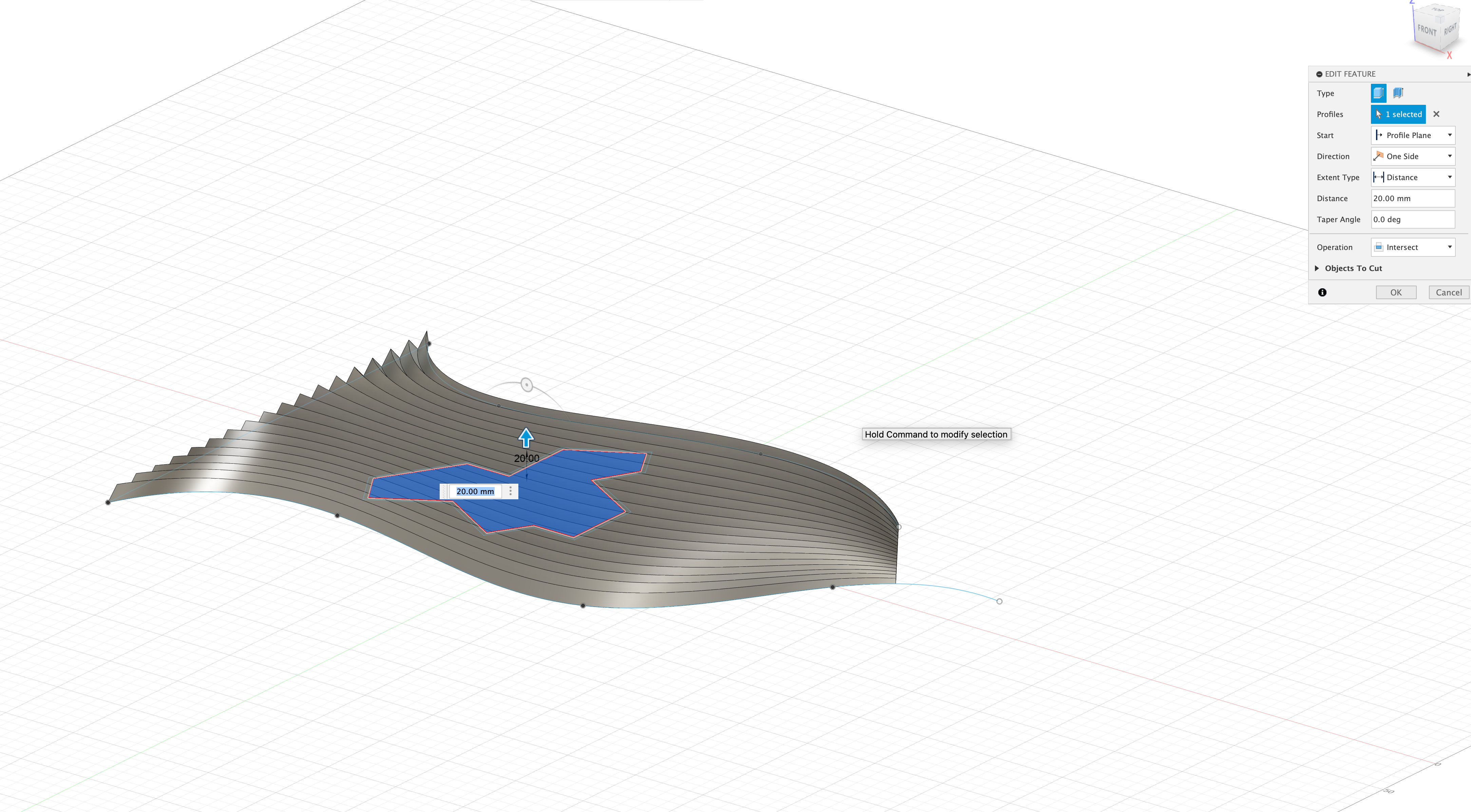
Extrude the Inner Penrose Shape:
- With the Penrose pattern sketch visible, select the shape just inside the offset (the original Penrose pattern).
- Go to the Create menu and choose Extrude.
- Set the operation to Intersect to create a 3D shape that matches the intersection of your sketch with the extrusion height.
- Adjust the extrusion height as needed, then click OK to confirm the operation.
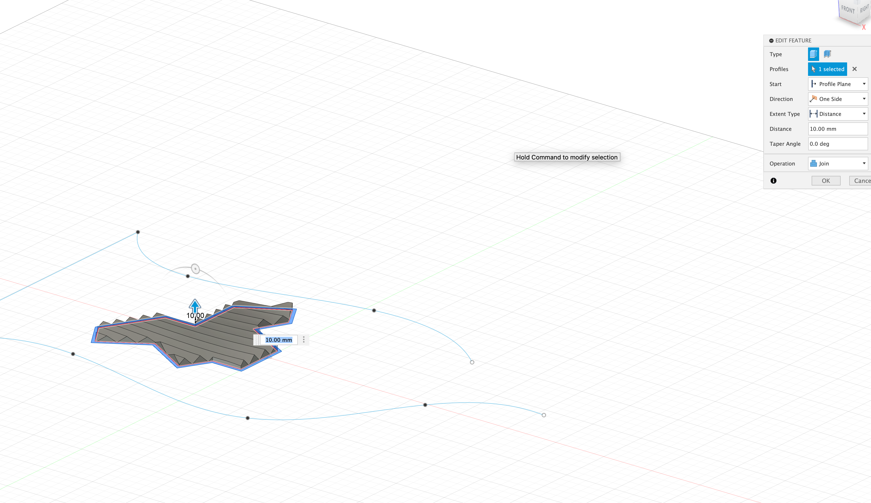
Extrude the Outer Shape to Create the Wall:
- Keep the sketch visible and select the outer shape (the area outside the offset).
- Again, go to the Create menu and choose Extrude.
- This time, set the operation to Join to add this outer extrusion to your existing shape.
- Adjust the extrusion height so that it creates a distinct wall between the Penrose pattern and the outer edge.
- Click OK to complete the extrusion.
Review and Finalize:
- Examine the model to ensure the wall is properly created and that the two extrusions have joined as intended.
- Make any necessary adjustments to the extrusion heights or wall thickness to fit your design.
Filling in the Bottom (Final Step!!)
Keep the Sketch Visible:
- Ensure that the sketch of the Penrose pattern is still visible in Fusion 360.
Select the Entire Penrose Shape:
- Select the entire Penrose shape that you have extruded earlier. This includes both the Penrose pattern and the outer wall if it was part of the extrusion process.
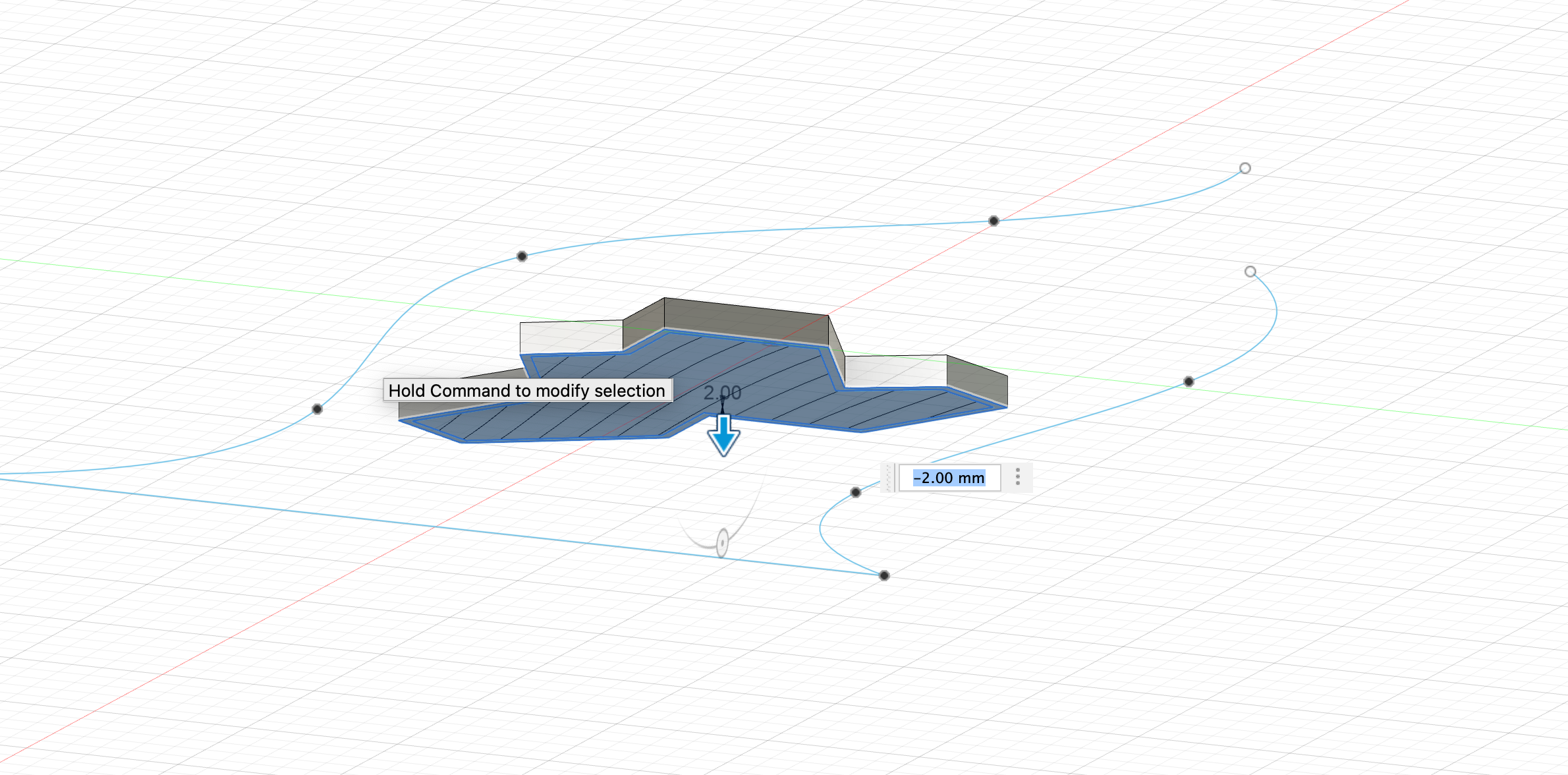
Extrude Downward to Create a Base:
- With the shape selected, go to the Create menu and choose Extrude.
- Set the direction of the extrusion to go downward to create a base. This will ensure that the model has a solid bottom when printed.
- Adjust the extrusion distance to add sufficient thickness for the base. Typically, a thickness of 2-5mm is adequate, but this may vary based on your specific design and printer requirements.
- Click OK to confirm the extrusion and create the base.