Password Safe / Keyboard Injector
by Smurfy_CH in Circuits > Microcontrollers
2490 Views, 35 Favorites, 0 Comments
Password Safe / Keyboard Injector

The modern world of today is just full of passwords. But how many passwords can one remember? Especially if you want a safe one and not the same password for all accounts. For a while I had an Excel sheet on a USB stick with all my passwords. But leaving the USB stick always on the PC is not safe, and not really easy to use. The copy past function never really made me happy.
A few months ago I stumbled upon the Raspberry Pi Pico, a small and affordable microchip that is capable of emulating a USB keyboard.
So I came up with the idea, to put my passwords on a micro SD card, hooked up to the Pico with a small display. With a selecting option to send the login-string straight to the computer.
To spice it up, I gave it a steampunk look with the help of my 3D printer.
The SD Card with the text file of login data and password can not be accessed by hackers, even if the Gadget is hocked up to the computer, the SD card is only accessible by the Pico.
Supplies


Electronic Parts
1 OLED display I2c 128x32 / 0.91" / 3.3 - 5 Volt
1 Micro SD card reader module 3.3 - 5 Volt
1 Rotary Decoder with push button option
1 Vacuum Tube (glastube Ø18mm) since this is only deco any tube will do that fits in the print part.I used a 1Z11P Half-Wave Vacuum Rectifier, I could get them for 1$.
1 Resistor 120Ω
2 Resistors 60Ω
1 USB Cable 2m MicroUSB to USB-C
1 MicroSD Card (the smallest one you can find will do. I use a 4GB)
3D printed parts from the STL file
PLA filament
Finishing (optional)
Sandpaper
Filler Primer
Spray Paint
Clear Coat
Tools
3D Printer, any 3D printer will do. Printing 0.2mm (0.4mm nozzle) Generic PLA 20% Infill No supports
Soldering iron
Electronic solder
Hook up wires multiple colors.
Hot glue gun (optional)
Tweezers and pliers
Print STL Parts

Download the STL Files and print them.
Any 3D printer will do.
Printing 0.2mm (0.4mm nozzle)
Generic PLA 20% Infill
No supports
Use a Filament with the color you like, or paint the parts before mounting any electronics.
Glue the Part Point_Point Into Point_Base

Use plastic glue and stick the printed parts Point_Point into Point_Base.
Mount Pico & SDCard Reader

Take 8 of the 1.7x5mm screws and mount the Pico and the micro SD card reader module to the Pico SDCard-Holder.
OLDE Display

Solder approx. 15cm long wires on the OLED display
Black wire on GND
Orange wire on VCC
Yellow wire on SCL
Green wire on SDA
The position of the BUS PIN might be different to the picture. Check the labeling on the pins while soldering the wires.
Use two component epoxy adhesives and glue the OLED Display into the OLED Display-Holder. Pay attention not to get any glue on the display that’s visible.
RGB LED on Vacuum Tube

Take the Vacuum Tube and the RGB LED.
Bend the pins at the Vacuum Tube with pliers, so that the RGB LED has a tight fit and stays in place.
Use two component epoxy adhesives and secure the RGB LED to the Vacuum Tube.
Connect PICO & SD-Card Reader


Solder the connections with some short wires on the Pico to the SD Card-Holder.
Check the SD-Card module for this little part (see Picture 1) on the backside.
This is a voltage regulator to 3.3 Volt. If this part is on the module, you can connect the VCC pin to 5 Volt. If it’s missing you have a 3.3 Volt model. In this case connect the VCC pin to 3.3 Volt on the Pico.
PICO PIN ______ SD CARD READER PIN
PIN 8 GND ---------------------- GND
PIN 39 VSYS ------------------ VCC
PIN 12 -------------------------- MISO
PIN 11 -------------------------- MOSI
PIN 10 -------------------------- SCK
PIN 13 --------------------------- CS
Make sure you check the SD Card Reader pins, the location of the BUS PINS might be different to the picture here.
Guide the wires for the connection over the backside of the Holder-plate. (see Picture 2)
The side "rail" must stay clear for sliding it in the tube.
Rotary Switch


Take the Rotary Switch and solder the middle Pin to one of the two pins of the opposite side. (See picture 3)
Attach a black wire, approximate 15cm long.
Solder two 15cm long wires of the same color on outside of the 3 pins. (Brown) Solder one 15cm long wire of a different color on the empty pin of other side. (Violet at the push-button function)
Mount the rotary button now on the Tube in the round hole and secure it with the nut. (The wires go in the opposite directions of the OLED Frame hole) (See picture 4)
Solder Up RGB LED


Meanwhile the glue on the Vacuum Tube and RGB LED should be dry.
First check the pins of the RGB LED.The longest pin usually is GND.
Check your LED:
Use 5 Volt and a 1k resistor, to check the pins.
Once the pins and colors are worked out, solder approx. 15cm long wires and the resistors to the pins of the LED.
Black wire to the GND pin of the LED.
Solder the 120 Ohm resistor to the RED pin and a red wire to the other end of the resistor.
Blue and Green each need a 60 Ohm resistor....
Secure the solder connections with Heat-shrinkable tubing.
With this resistor values the LED should get approx. 10mA power. You might alter the resistor values according to your LED brightness. But don’t go over 20mA.
Vacuum Tube

Glue the Vacuum Tube into the Point_Point / Point_Base part.
Glue it in, till about half way.
Once it’s dry, glue that part Point_Point / Point_Base & Tube to the PWT_Body.
Lead the wires out to the other end of the PWT_Body.
OLED Display

Glue the OLED_Display_Frame with the display into the hole of the PWT_Body. The wire connection part of the display, facing the Vacuum Tube.
Finishing the Hardware Work


Now move the Pico SD Card-Holder as close as possible to the end of the USB part of the PWT_Body.
Trim the wires and solder them straight on to the Pico according to the main sketch.
Once that is done, slide the Pico SDCard-Holder into the PWT_Body.
Use the small rail on the wall, inside the tube, to guide the Pico SDCard-Holder. Make sure all the wires slide in behind the USB port.
Slide on the LID_USB part and secure it with 3 screws. (Optional, you can also use a small strip of paper or a bit of paint, to give it a tight fit. It should stay removable to get access to the SD-Card).
The hardware part is done now.
Software Installation
Fortunately the Pico makes it really easy to add the software part.
Plug in the Micro USB cable into the Pico and the other end to your PC.
After a few seconds a new small drive should show up on your PC. As if you plugged in a USB pen drive.
Open the Pico Drive with the explorer.
Then go to https://circuitpython.org/board/raspberry_pi_pico/ and Download the .UF2 File now. Save the File on your computer.This is the Circuit Python system for the Pico. I Used the Version 8.x.
This gadget was developed on a German keyboard. Since the ASCI standard of the HID library is different to the US layout you need to download the GERMAN Python system. The download link above will download the correct UF2 file.
Copy this UF2 file to the Pico drive. After a short time the Pico drive reboots.
Open the drive again and delete all content in it.
____________________________
Download the ZIP File PWT_ISO.
Unzip this file and copy the content as its shows up in the Zip file, to the now empty Pico drive.
That’s it!
Your Password Safe should boot up now, flashing the LED in the Vacuum Tube. After 3 minute or pressing the rotary switch button it stops flashing. The display keeps showing BOOTING NOW. That's because you don’t have a SD-card insert. Once you insert the SDCard with the file PWData.txt you need to reboot the Password Safe. Unplug it and plug it in again.
DO NOT CHANGE THE SDCard WHILE THE Password Safe IS POWERD ON! (Most likely it would corrupt your SD Card and you need to format it again)
SD Card Preparation

Formate the SD Card in FAT32!
DO NOT CHANGE THE SDCard WHILE THE Password Safe IS POWERD ON! (Most likely it would corrupt your SD Card and you need to format it again)
This gadget was developed on a German keyboard. Since the ASCI standard of the HID library is different to the US layout, only the following characters are allowed to be use to send with the Password Safe. Other characters may translate wrong or even freeze the Pasword Safe, till you reboot it.
a b c d e f g h i j k l m n o p q r s t u v w x y z 0 1 2 3 4 5 6 7 8 9
A B C D E F G H I J K L M N O P Q R S T U V W X Y Z
+ ö ü / ; : . * % = ! £ & ) ( @ # $
On a US Keyboard the letters Y & Z are swapped opposite. You can change this in the script file code.py. Located on the Pico device. (Remove the y - z swap lines in the source code, line 162 -169).
Stick the MicroSD Card into a USB Reader for a PC, plug it into the USB port of your computer.
On the SD card you need to write a file with your data on it.
To write the file you must use an Editor, like Notepad for example.You can’t use Word or similar Programs because the files of this programs contain information about font size, colors etc.
So open your Editor on the PC.
And write the data that you want to send to your PC later.
1. Line This is the Name that shows up in the Display
2. Line PWSTART1
3. Line Text that is injected to your PC
4. Line More text that is injected to your PC
x. Line (last Line) PWEND1
Additional data needs to start again like the one above. But you need to increase the number after PWSTART and PWEND by 1.
At the end of your input you need to add one single line. For example P.W.S. Version 2.0
Here is a demo PWData.txt file.
Demo-file as ZIP file as download.
—————————————————————————————
Mail Login Demo
PWSTART1
https://www.smf.pcaarburg.ch/zzz-pwt/PasswordSafeTestDemo.html
Smurfy-CH@instructables.com
admin1234567890admin
PWEND1
Password Check
PWSTART2
https://password.kaspersky.com/
Hallo%This%isMyNew40LetTerPasword0123Go(4)It
PWEND2
Open Word To Test
PWSTART3
Dear PWT User
this is only a few examples for using the Password Safe.
Feel free to add data and experiment with this PWData.txt file on the SD Card.
PWEND3
P.W.S. Version 2
———————————————————————————————
Note the increasing numbers at PWSART and PWEND.
Write it with the editor, with NO EMPTY LINES between.
Save your file now to the SD Card and name it PWData.txt
Unplug the Password Safe from the USB port.
Insert the Micro SD card into the SD Card slot of the Reader from the Password Safe.
Plug the Password Safe in to the USB port of your PC.
Wait till its finished booting up.
Select by turning the rotary switch button, to the first data field, showing Mail Login Demo on the display.
Push the rotary switch button. (The URL of the demo page gets injected to the URL window of the browser)
Press ENTER on the keyboard. (The demo page opens a login window in the internet browser)
Here you click into the field Nutzername (username in German)
Push the rotary switch button. (The username gets injected to the selected input line)
Click with the mouse into the Password line. (The input line is selected for data input)
Push the rotary switch button. (The password gets injected to the selected input line)
Use your mouse to click on the screen the button Anmelden. (register in German)
The LOGIN OK screen shows up now.
Using Infos & Good to Knows :-)
Reinstalling the Pico new:
Unplug it from the USB port. Locate the little withe button on the Pico, 1cm beside the USB port. While plug it in again, you press this button and release it after. The Pico will start new and show up as USB-drive. Download nucke_uf2 and save the uf2-file on the Pico. This will set the Pico to factory reset. You will loose all data on the Pico and you need to install Circuit Python new.
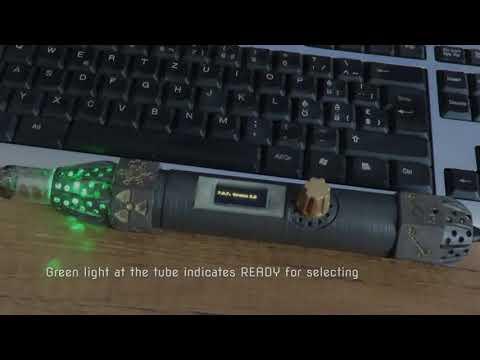
The LED lights on the vacuum tube indicates the status of the Password Safe.
If the Tube LED is flashing (boot delay is on for 3 minutes. It can be interrupted by pressing the rotary push button)
If the Tube LED is green then you can select a new data field.
If the Tube LED is red, the Password Safe is sending data.
If the Tube LED is blue, it waits for the next button to push so it can insert the next line of data.
You can open an editor or word on your PC to test and see the outputs of the data.
Since you need to select the input fields on the internet, before sending any data, the ENTER command is not send by the Password Safe. You need to press ENTER on the keyboard manually.
The Password Safe can be connected all times to your PC. The data on the SD-Card should be safe, since there is no direct access from the internet to the SD-card.
For a secure start while booting your PC, the Password Safe has a boot delay of 3 minutes. In that time the Vacuum Tube flashes rapidly. You can shorten that time once the PC is booted up by pressing the rotary switch push button.
This gadget can be used for any other keyboard input events.
Just experiment with the PWData.txt file and check the results.
Info about the keyboard commands can be found here:https://docs.micropython.org/en/latest/library/pyb.USB_HID.html
You can place the 3D printed STL_USB_Cover over the USB plug and behind the USB-lid. To prevent the easy removing of the SD-Card.
Please Note:
This is a hobby project and it is not tested by experts or hackers. You use it at your own risk. Connecting it wrong or poorly soldering can damage your Pico-device or your PC. All SD-Cards can go corrupt and the data on it can get lost. So make sure you have your passwords saved somewhere else too.
The software is a work in progress project, you might find updates for it. I plan to add a PIN LOCK at the start of the Password Safe.
An internal editor to write and decode the password data (PWData.txt), so the passwords are not as an unprotected text file on the SD card.
If anyone is adding or optimized the code, I would be thankful to get a copy of the source code too :o)
For altering or inspecting the source code on the Pico you can install the Thony Python IDE. https://thonny.org/ there you find all information how to use and access the python code.
Happy 3D print & soldering ;o)
Trouble Shooting
Password Safe has no reaction after plug in the USB port.
Bad USB cable
Solder point short connection.
Password Safe display is dark.
Check if SCL is on GP15 and SDA is on GP14
Password Safe display freezes at BOOT NOW! message.
No SD-Card insert or the file PWData.txt is missing or has wrong contend.
SD-Card reader is wrong connected.
SD-Card has not FAT32 or the size is not supported by the card reader.
Password Safe vacuum tube LED show wrong colors.
Swap GP2 GP3 and GP4
Password Safe rotary push button moves the selection in the wrong direction.
Swap GP8 and GP9
Password Safe injecting wrong text or freezes while sending text.
PWData.txt contents forbidden characters or PWSTARTx / PWENDx is messed up. Missing or not matching number at PWSTART / PWEND.
PWData.txt was not written and saved with a editor.
A non German python .uf2 file was installed on the Pico.