Particle Photon Home Alarm System
by thinice in Circuits > Microcontrollers
6837 Views, 32 Favorites, 0 Comments
Particle Photon Home Alarm System
Here is my first instructable! It has been three years since I met Arduino. I tried different DIY projects but I haven’t post one before. Making an alarm system may not seem a complicated project, but If electronics is only your hobby-not your proffesion, then it is great deal. The previous version of my alarm system was sending SMS from a Mobile Phone. I hacked its buttons and get Arduino to simulate the button press. Anyway it is the old story.
A couple of weeks ago, I met Particle Photon. It is a new development board, programmable like Arduino and it has a built in WIFI. It is very good if you want to build a cloud based system. Of course I bought one and began to think of what I can do. I decided to make my alarm system again, but this time it will not send SMS; it will push notification to my mobile phone.
In my system, the photon has got a 433 Mhz receiver on it and I use cheap wireless door-window sensors, remote controls and a PIR sensor. Sensors sends some codes to the receiver and the Photon posts a message to the PusihingBox cloud service. You can set a mail or a notification on your mobile phone from the Pushing Box.
Materials
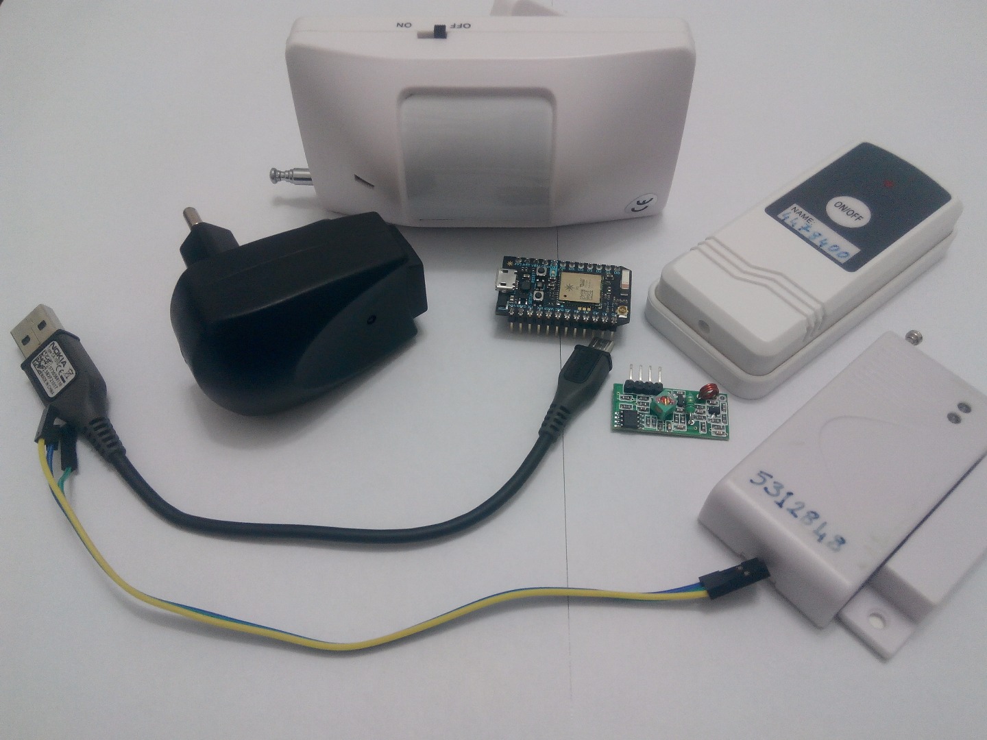
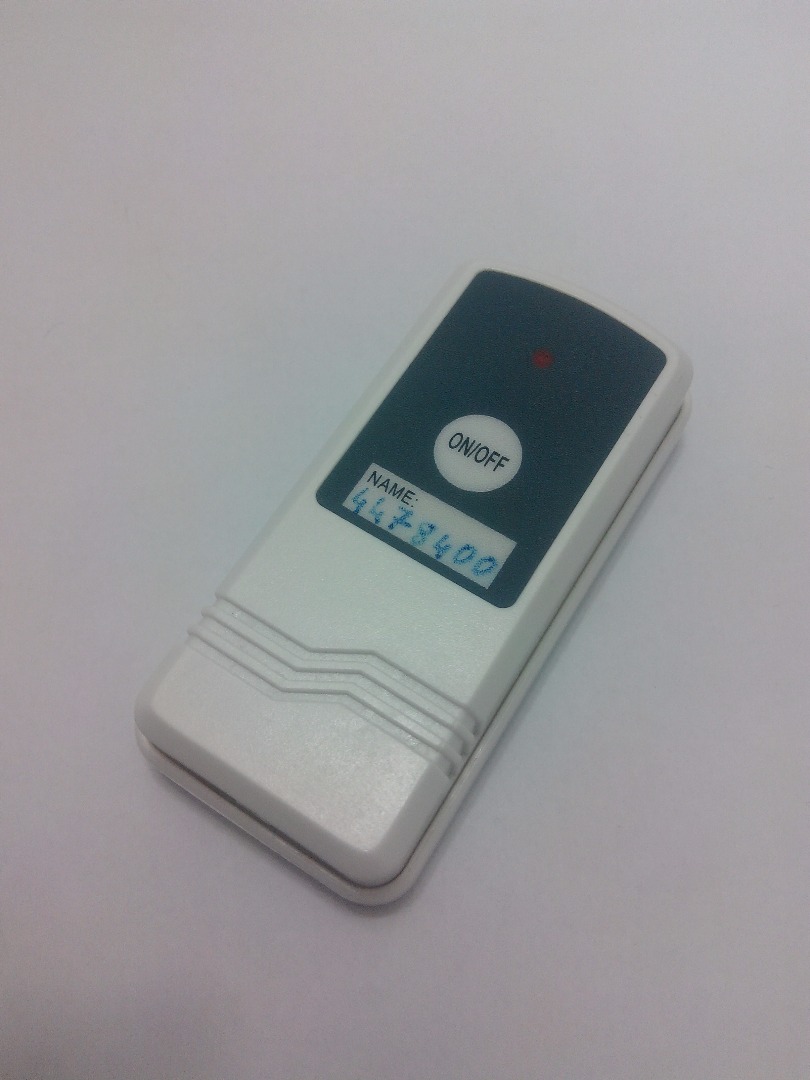
You will need:
- Particle Photon with headers(1)
- 433 Mhz Receiver(1)
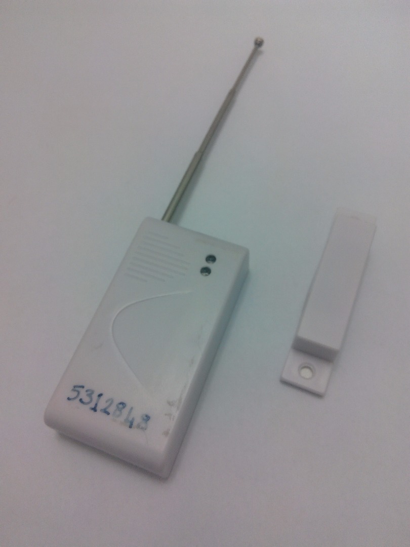
- Wireless Door-Window Sensor (1)
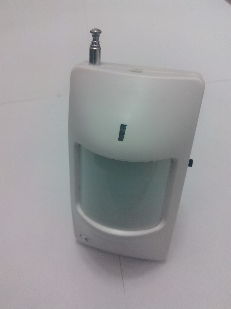
- Wireless PIR Sensor(1)
- 433 Mhz Remote Controller (or a garage door remote, wall switch remote, etc.)(1)
- Jumper Cable Female to Female(3)
- USB Micro B Cable(1)
- 5V Power Source (power adapter, mobile phone charger, computer, etc.)
Preparing the Photon
If you are using Photon for the first time, you need to set it up. It needs to learn your network parametres. Out of box, Photon doesn’t come with a USB cable, so you need a Micro USB-B cable to power up the device. Plug the usb cable to a power souce- your computer is a good choice. Then the RGB led on the board should blink blue.
For the first setup you need a smartphone and the Particle application. You can find the app in google play store with the name “Particle”. Open the app in your phone. You need to sign up a new account for Particle. You will use this account for Build IDE.
After you sign in, follow the instructions on the screen to connect your device to WIFI. This will take a little while. In this period, photon will restart for several times, this is normal. At the end when Photon is ready, on your moblie phone application you can see the green “online” sign.
For more detailed information about connecting the device, you can visit here.
Learning the Codes in the Sensor Messages
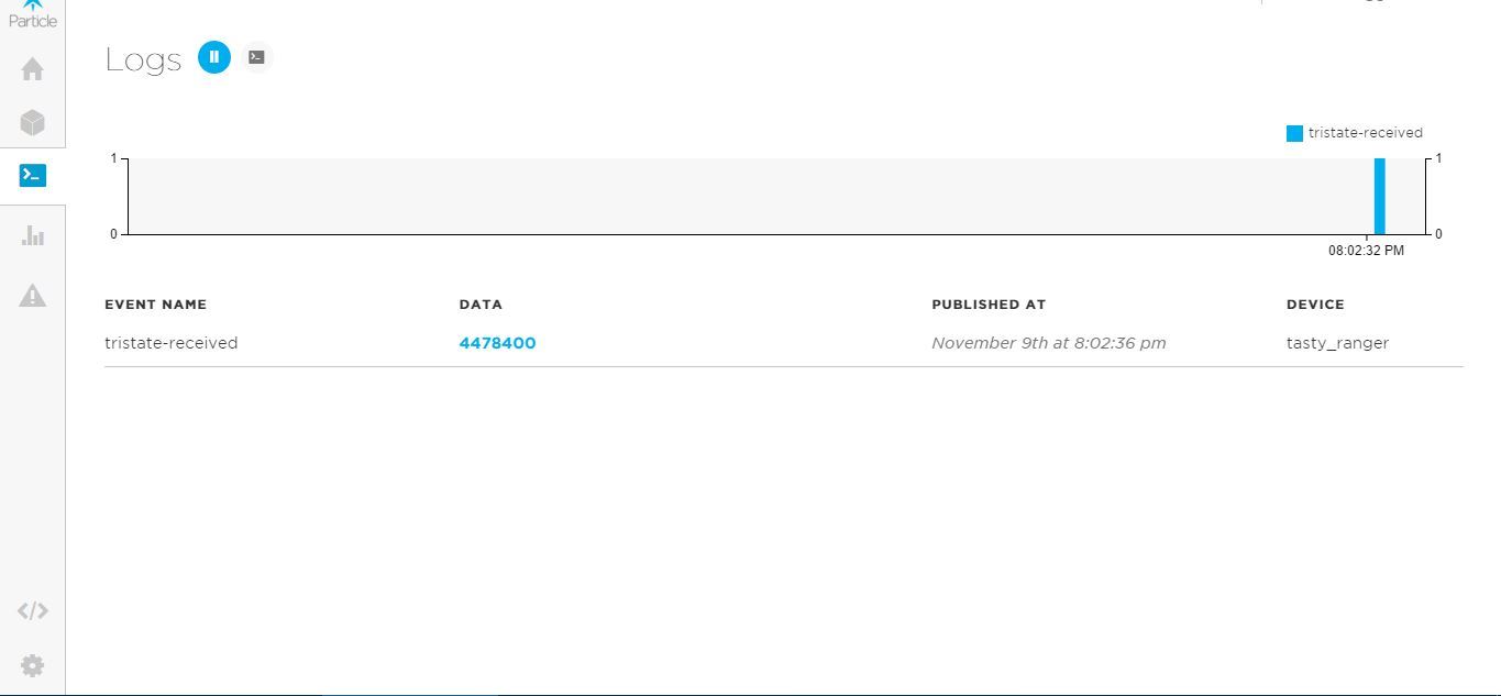
As I told before, both the remote controls and the wireless sensors send a message consisting of a number. Before building our system, we need to learn and note down these numbers.
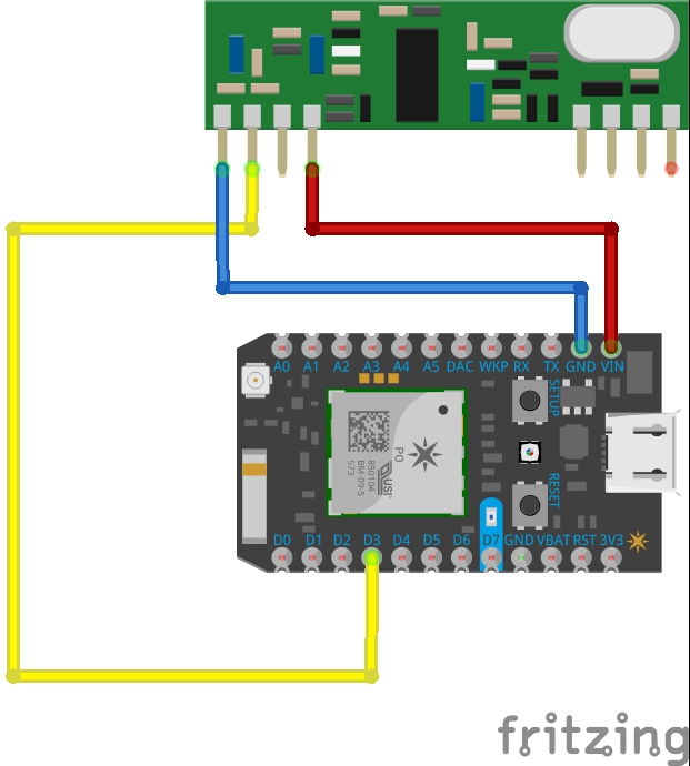
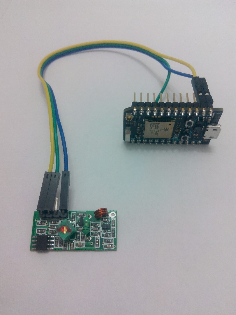
First of all we need to connect the receiver to the Photon. Pin connections are like this;
Receiver Photon
Vcc ------------------ Vin
Gnd ------------------ Gnd
Data ------------------ D3
You can give a look at the Step 5.
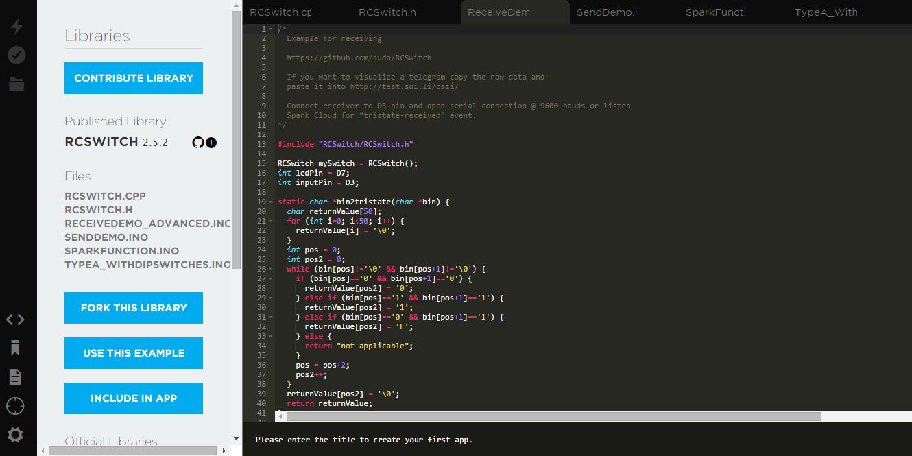
After you prepare the connections now it’s time to work on the code. Go to the Particle build page and sign in. On the left side, you can see the Libraries tab. Search for the “RCSWITCH” library. Above you will find an example .ino file called “RECEIVEDEMO_ADVANCED.INO”. When you open it, you can see the code in the terminal. After you click on USE THIS EXAMPLE button, change the following code on line 65;
Spark.publish("tristate-received", String(delay) + " " + String(tristate));
to;
Spark.publish("tristate-received", String(decimal) + " " + String(tristate));
you can now flash (load) the code to your Photon by clicking the flash button on the left .
After you flash the code in the Photon, Photon will begin to listen any messages from 433 Mhz. Now you can send messages from the remote controllers and wireless sensors. To see the incoming messages, you need to go to the Dashboard page. There you can see the incoming sensor messages in the LOGS tab. This is where you note down the each item’s message content.
Example:
Remote controller : 1111111
Door Sensor : 2222222
PIR Sensor : 3333333
Setting Up the PushingBox and the Notifying Services

First you need to log in Pushingbox. You can only log in with a Google account. Go to the “My Services” page and add the service you need. I added e-mail service and an android notifier Newtiftry. There are several services for different platforms (IOS, Windows Mobile, etc).
Now go to the “My Scenarios” page and add a new scenario, it is quite easy. Just follow the instructions on the page. After you add your scenerio, you will see the DeviceID. Note it down to use later.
Further information about PushingBox.
Circuit

.jpg)
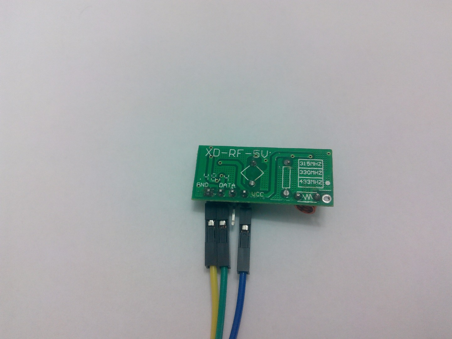
Actually you have already built the circuit in step 3. You can use the same connections.
If you want to improve the signal range, you can solder an antenna cable.
Code
The code is a combination of the RCSWITCH library example and the PushingBox example. I changed some parts and add a few variables. I know it's not the best code for a project like this, but at least it does what I want for now.
You need to change the sensor messages and PusingBox device id, the parts to be changed are commented in the code. What you should be careful about is that; when you use a code in online Photon Build IDE, you have to add the library into your application. Just typing "include" in the code isn't enough. So you need to search for the library and click "Use This Library", the library will be automatically added.
Downloads
Limitations and Improvements
There are a few limitations in my project. First one is the internet connection issue. The system is totally dependent on internet. If there is no connection, then there is no security. Second one is the power. If the system power goes off, then there is no security again. Another problem is about 433 mhz. I guess it’s quite easy to hack the signal messages. You may think the project is nonsense then because of all these limitations and security issues, but anyway It’s a DIY project, it’s all about DIY soul. And you can always improve something.
You can use a more reliable receiver working on different frequency and build your own wireless sensors. You can add a keypad and guard the system with a password. About the power issue, you can always add a back up battery. And finally for the internet connection, you can use Particle Electron with built-in 3G cell.
I would like to add a function to guard/unguard the system from an android mobile phone, but I could't find a suitable application. Building a new application to send HTTP POST request is very difficult. If you know an app that I can use, please tell me.
I am awating for your comments and ideas.