Parametric Media Console - Using Locally Sourced Timber
by diggoryrush in Workshop > Furniture
12658 Views, 90 Favorites, 0 Comments
Parametric Media Console - Using Locally Sourced Timber


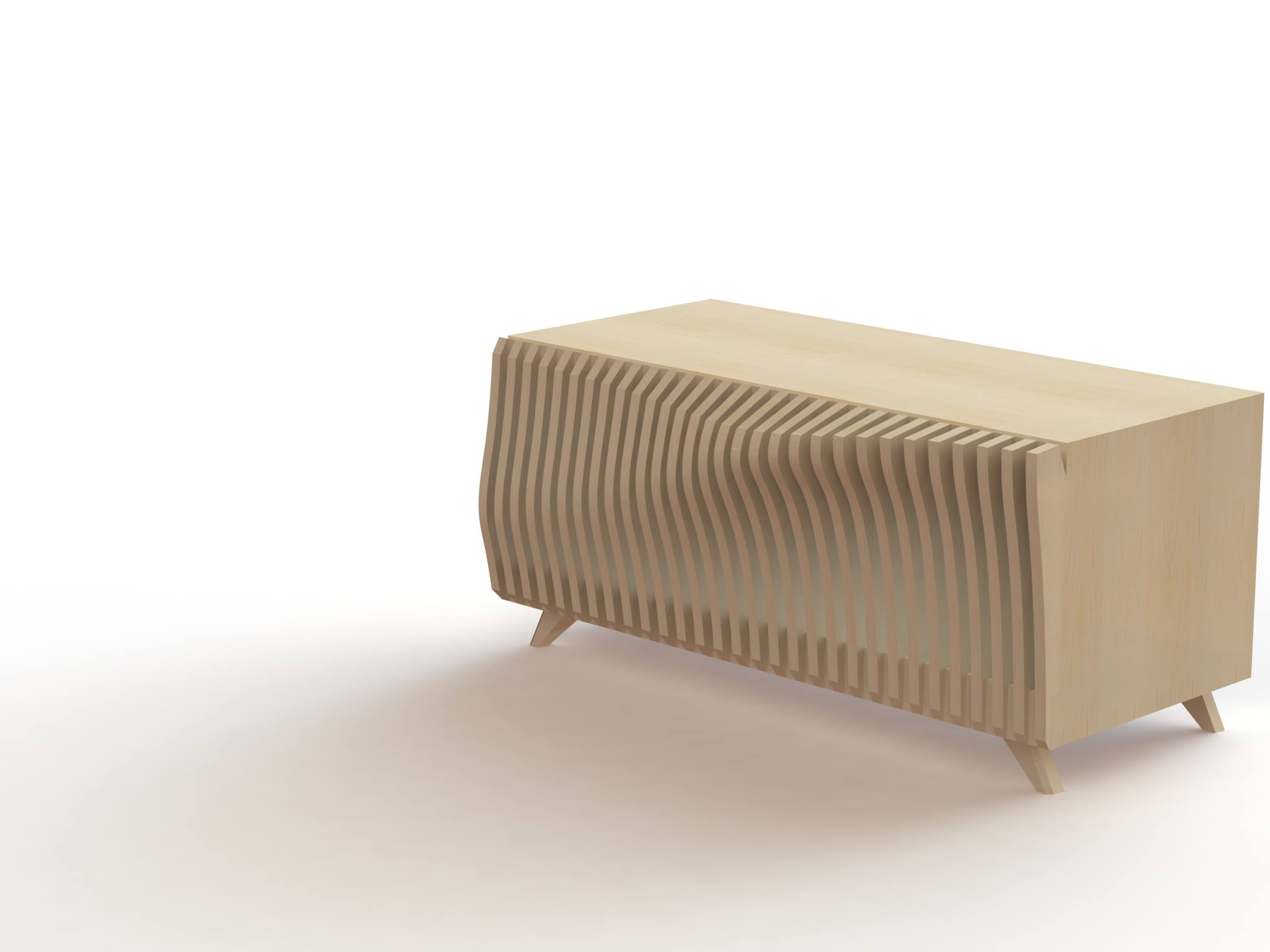
My design is a small media console. It presents some real design challenges in making and even drawing the shapes in CAD, so buckle up!
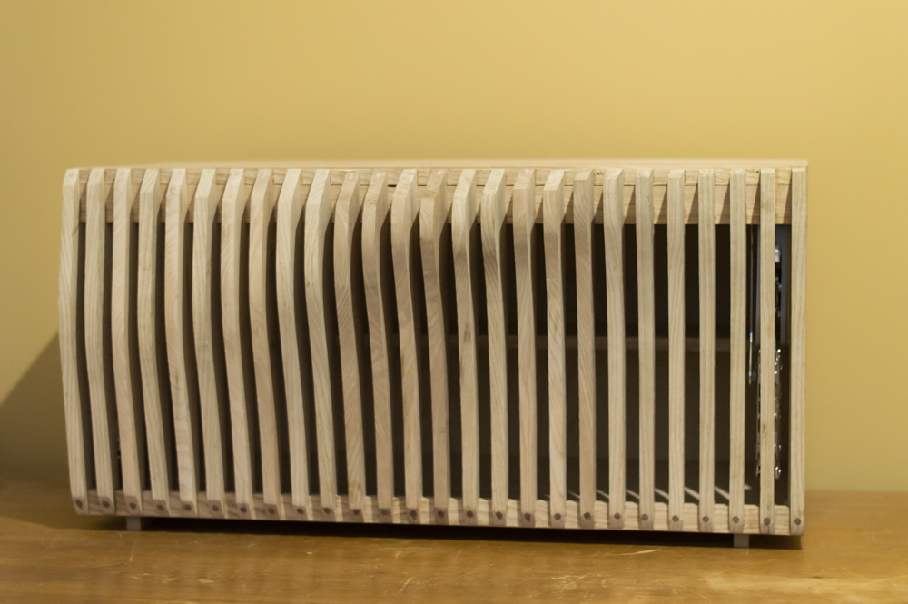
I really liked the idea of stepping away from common shapes and making a beautiful and functional object that will really catch people when they walk in.
The design utilises a curved louvre front that allows great airflow for electronic items. It blends associative design technology/algorithmic modelling with traditional joinery. The wave-front of the cabinet was developed primarily in Grasshopper using a parametric equation.
Sketches
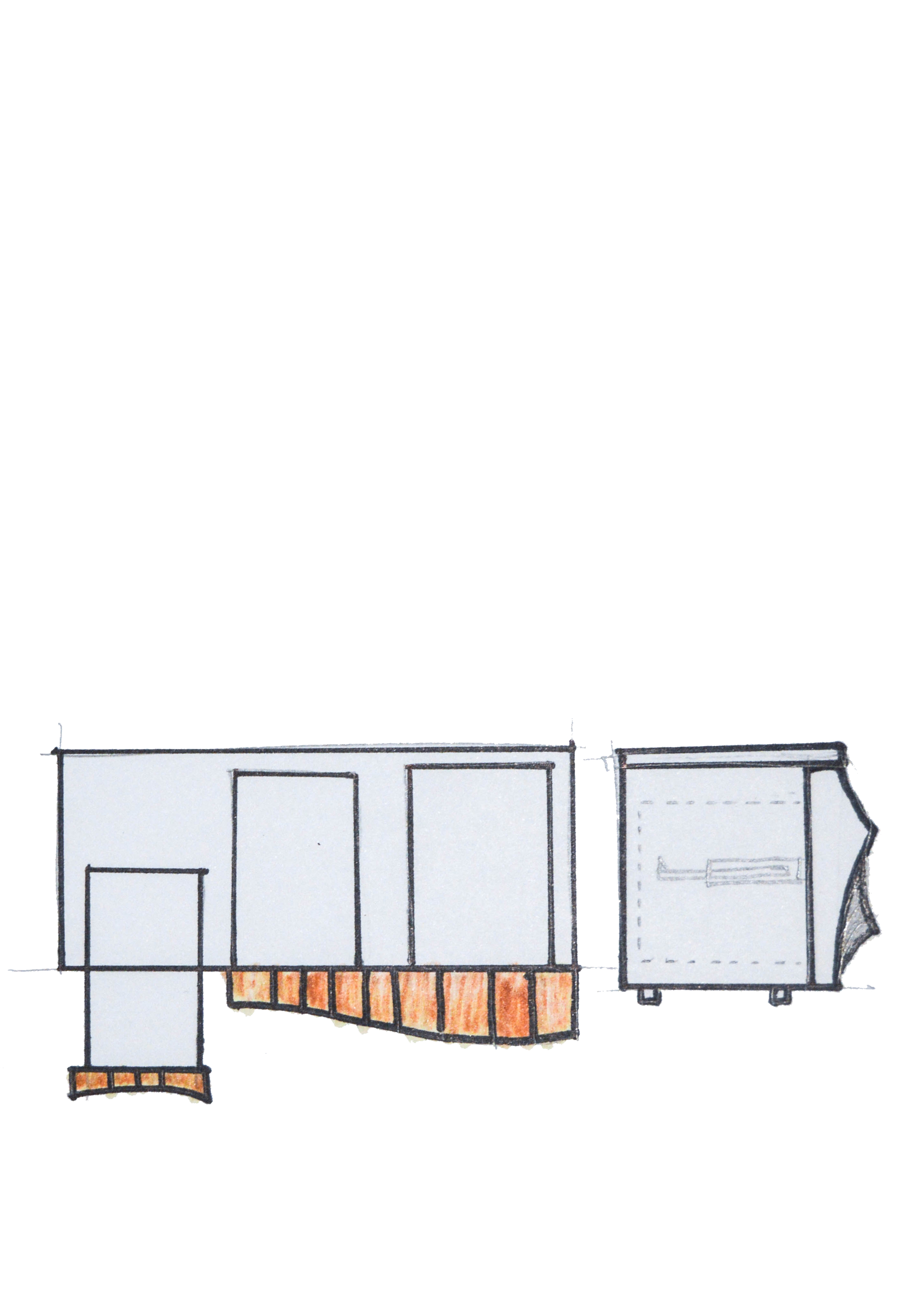
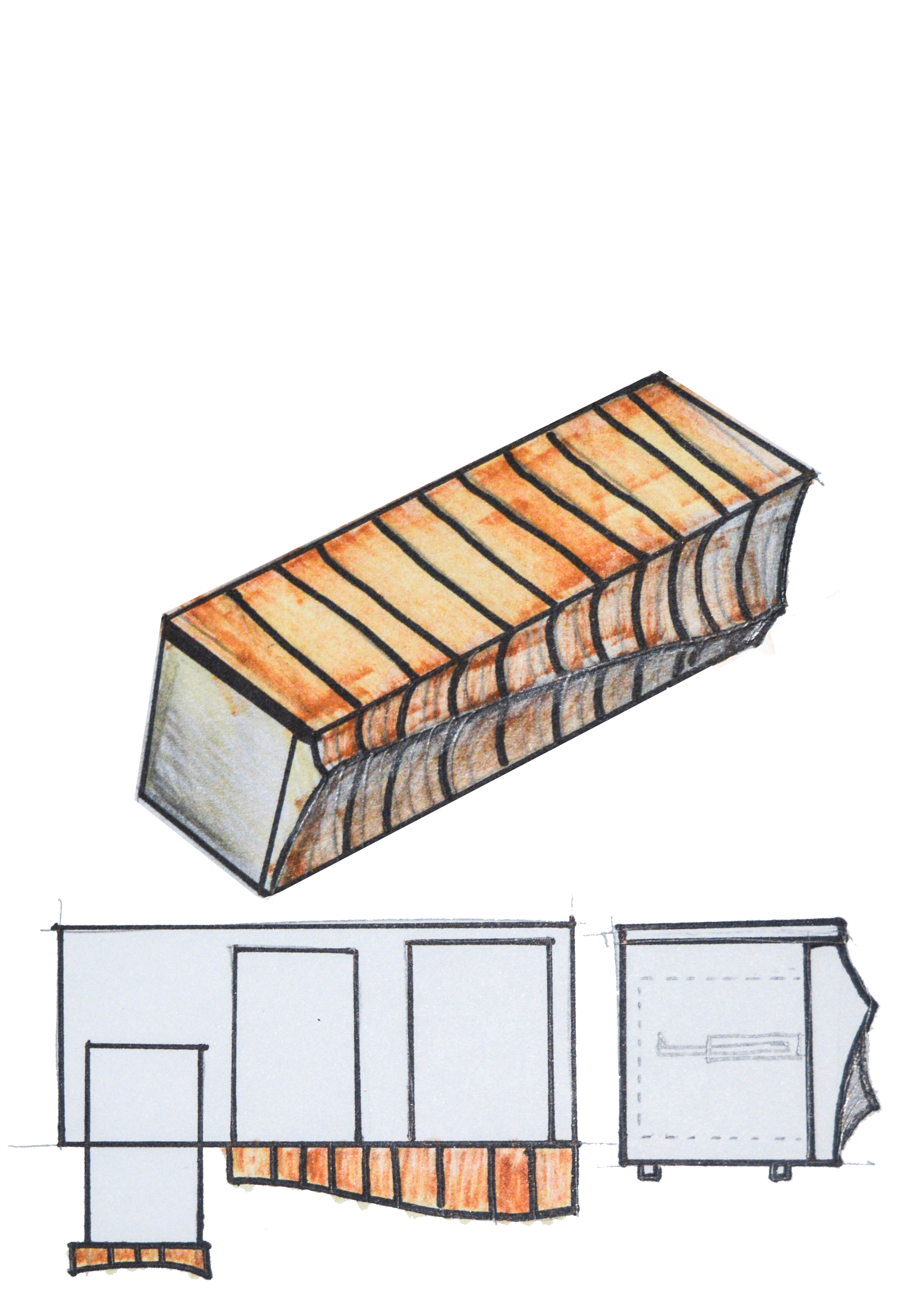
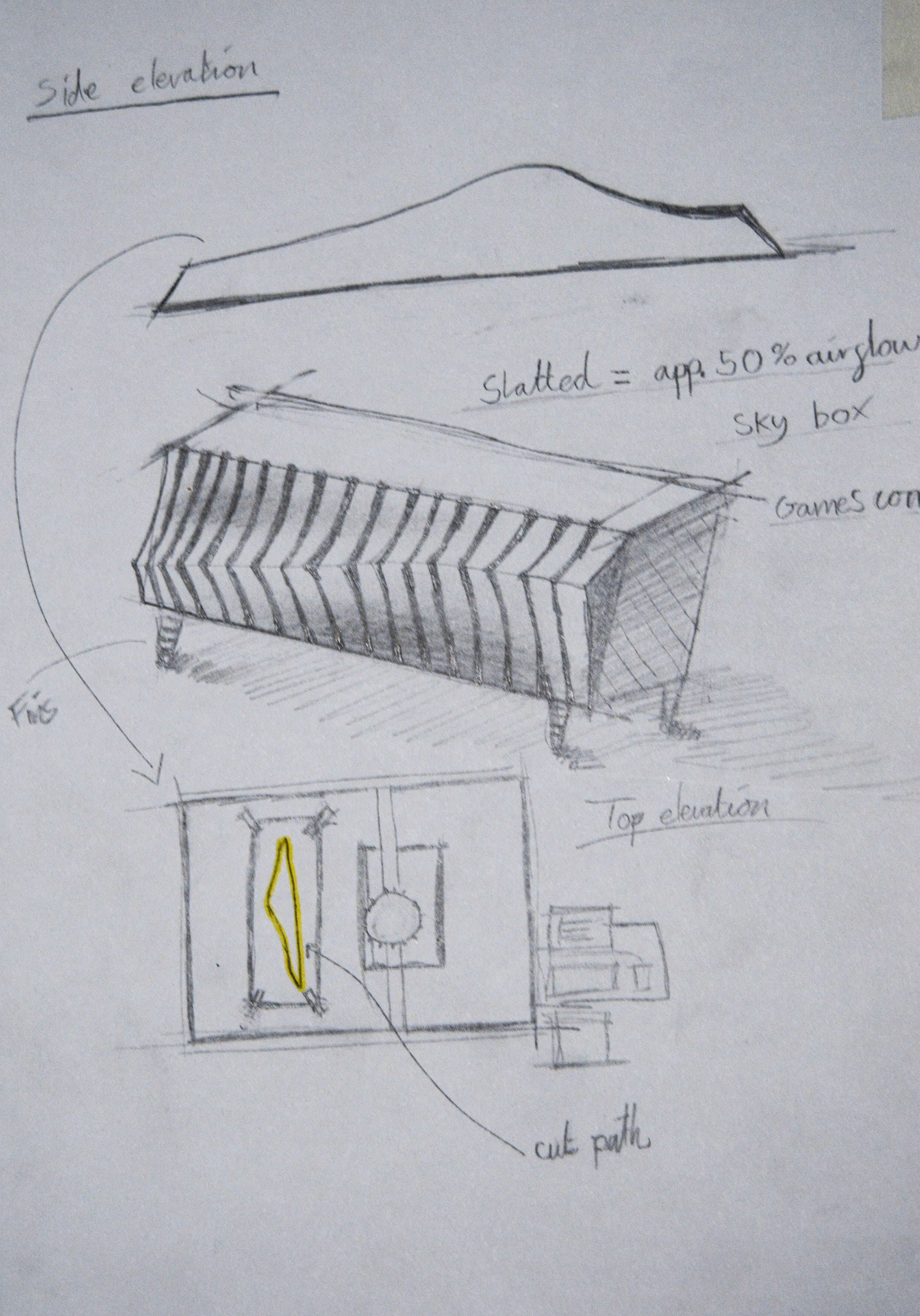
Here are some of my early sketches when designing this unit. In case anyone is interested.
CAD
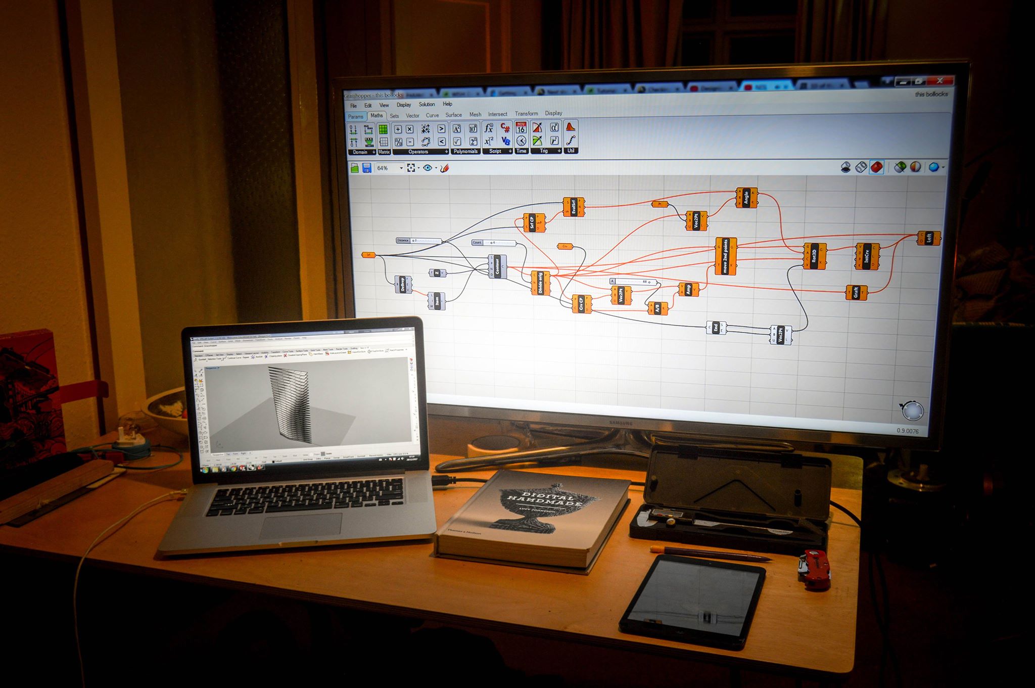
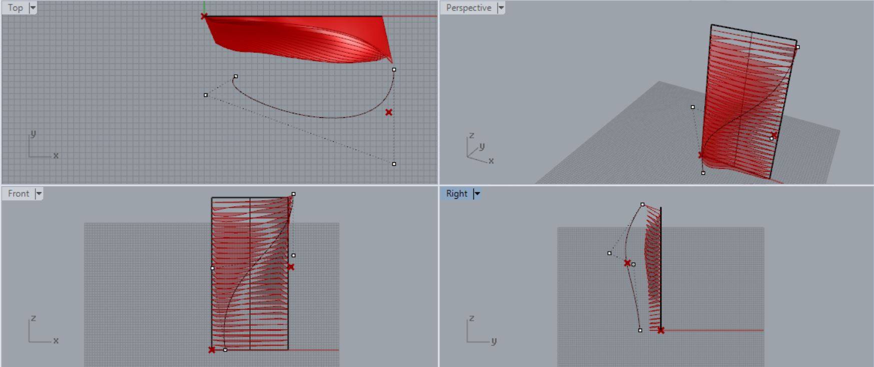
I mentioned at the beginning of the project that it was designed with associative design technology based around algorithms. Here's a screenshot of what makes the shape for the front of the cabinet. The shape is developed from a parametric equation based in a set of known parameters, fixed geometry.
I'll now try my best to explain this simply...
The first picture shows the brains of the operation if you will. This is the programming that tells the computer what values to assign to different inputs. For instance there is a randomly generated net of control points and the software needs to know. How many points will there be? How random will they be? (normally controlled by a factor of 1-10) Where will they be on the page?
The second picture shows the shape starting to come together. As you can see in the top view (top left) there is a black curve. This is what we would call an attraction curve. The randomly generated points are told to be attracted to this curve by a factor of my choosing.
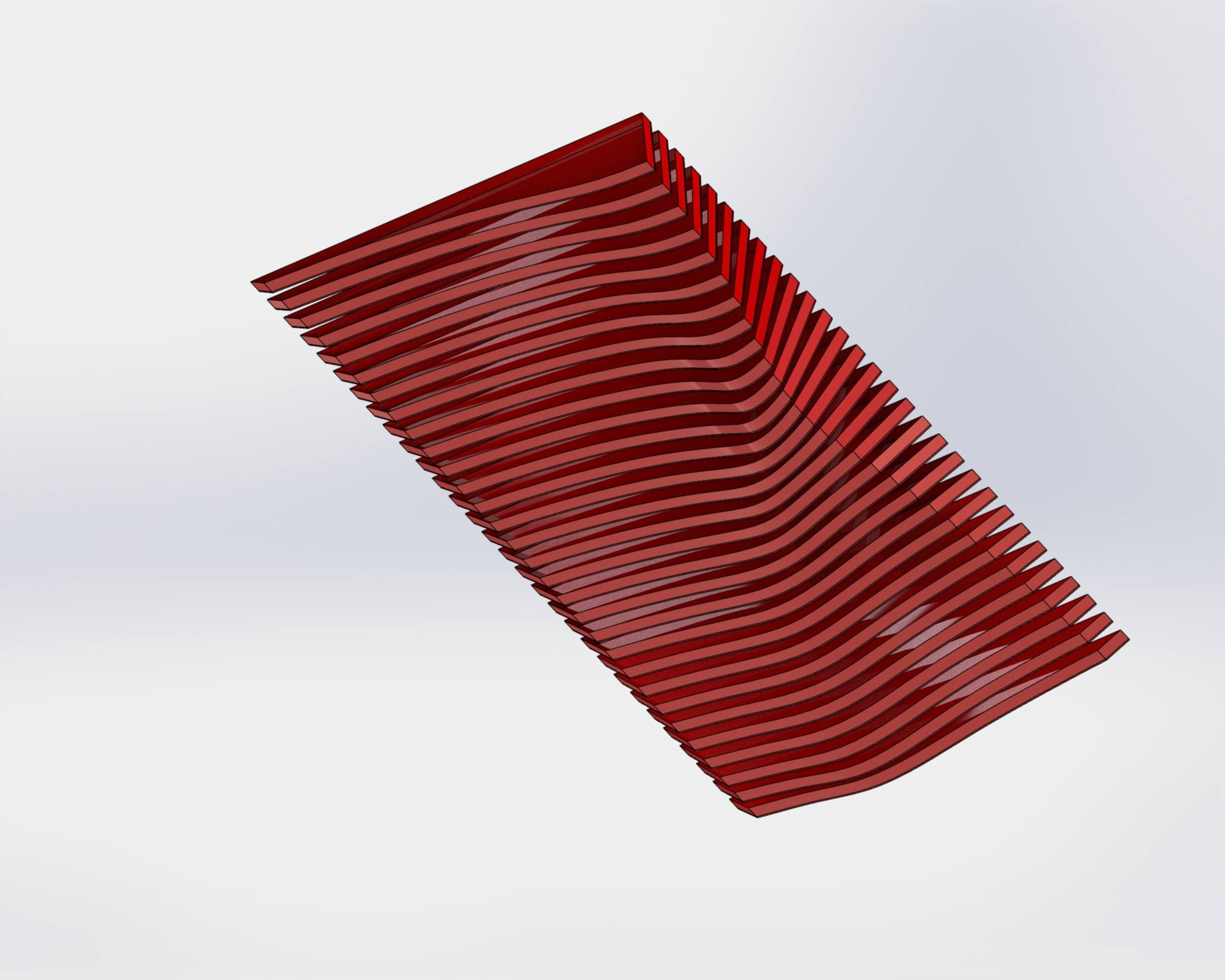
The point cloud is then taken and separated into groups and made into planes (2d surfaces). These are then baked (weird terminology I know) , saved and then individually flattened.
I then assembled the extruded planes, or as I call the fins/ribs in Solidworks as an assembly.
Making the front of this cabinet took me three months and I believe requires it's own instructable. However, if you are interested you can look on youtube at videos of Grasshopper which is commonly available as a plugin for Rhino (the main software I used) and see how it works.
Also if anyone would like any tutorials on any CAD software leave a comment.
Materials
For materials I used primarily solid Ash, a hardwood with a light colouration and prominent grain.
The top and base are 700mm x 300mm x 18mm - Ash
The sides are 330mm x 300mm x 18mm - Ash
The ribs/slats are 330mm x 80mm x 12.5mm
The back is 674 x 304 x 6mm - veneered mdf
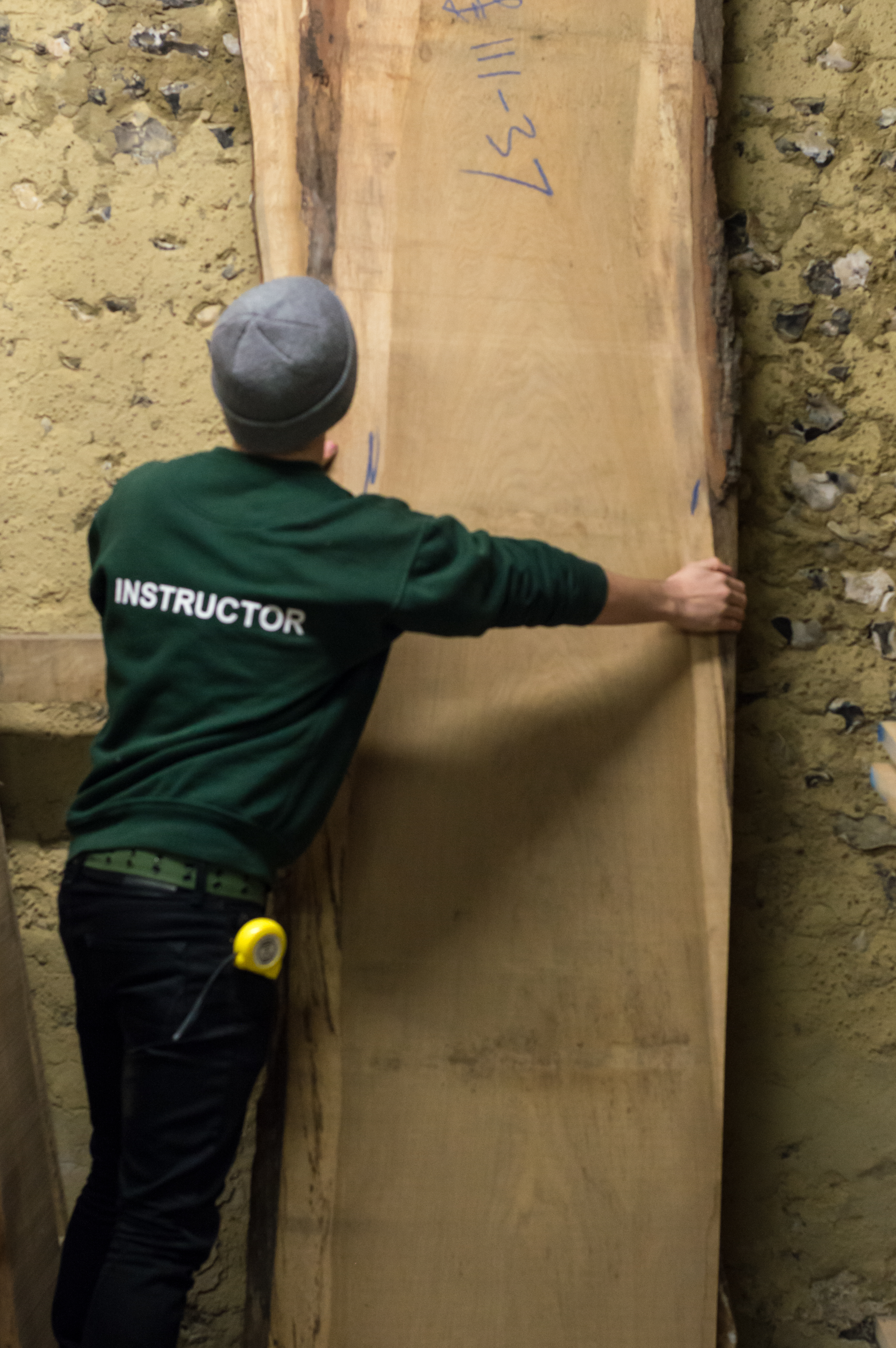
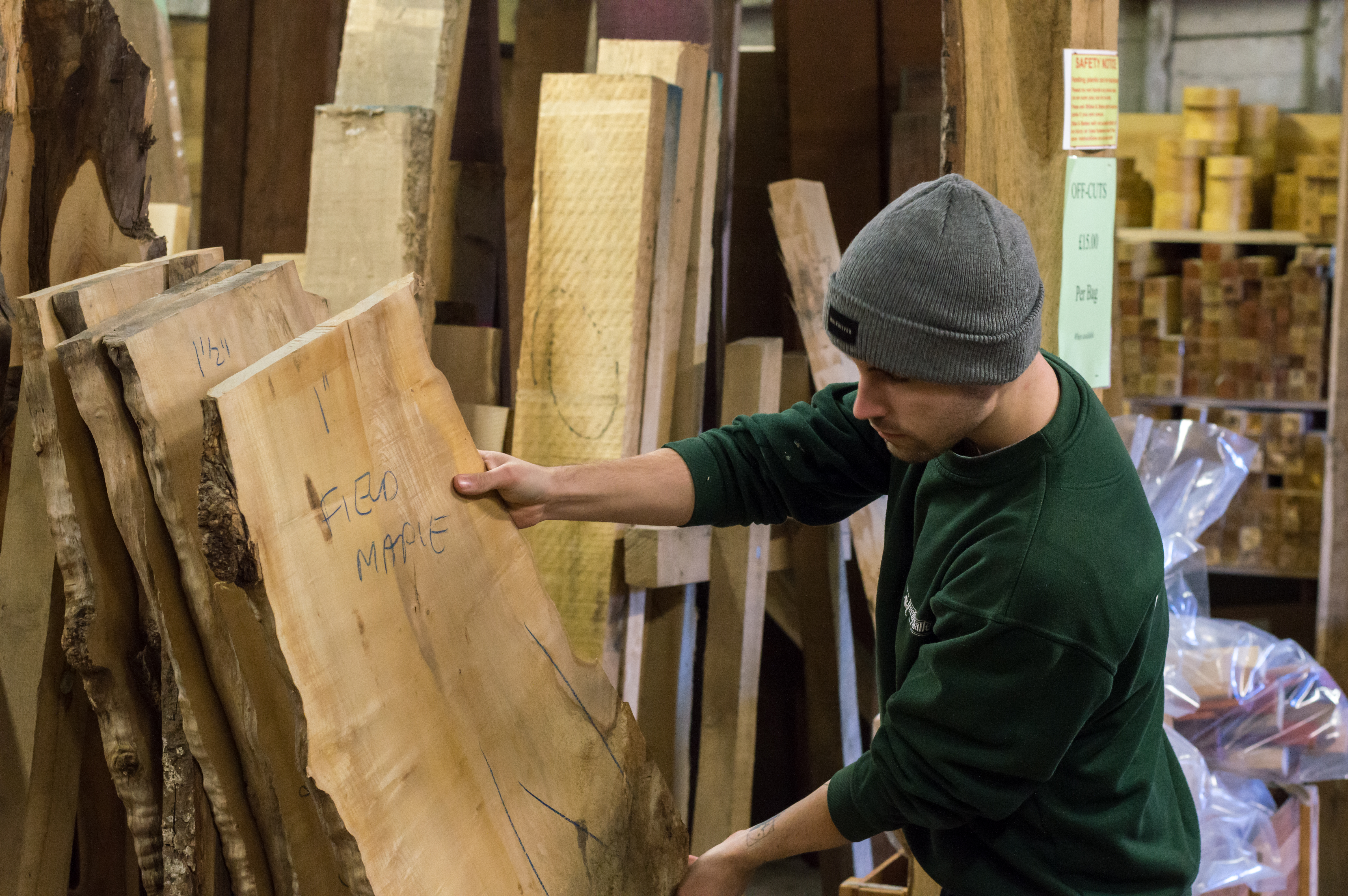
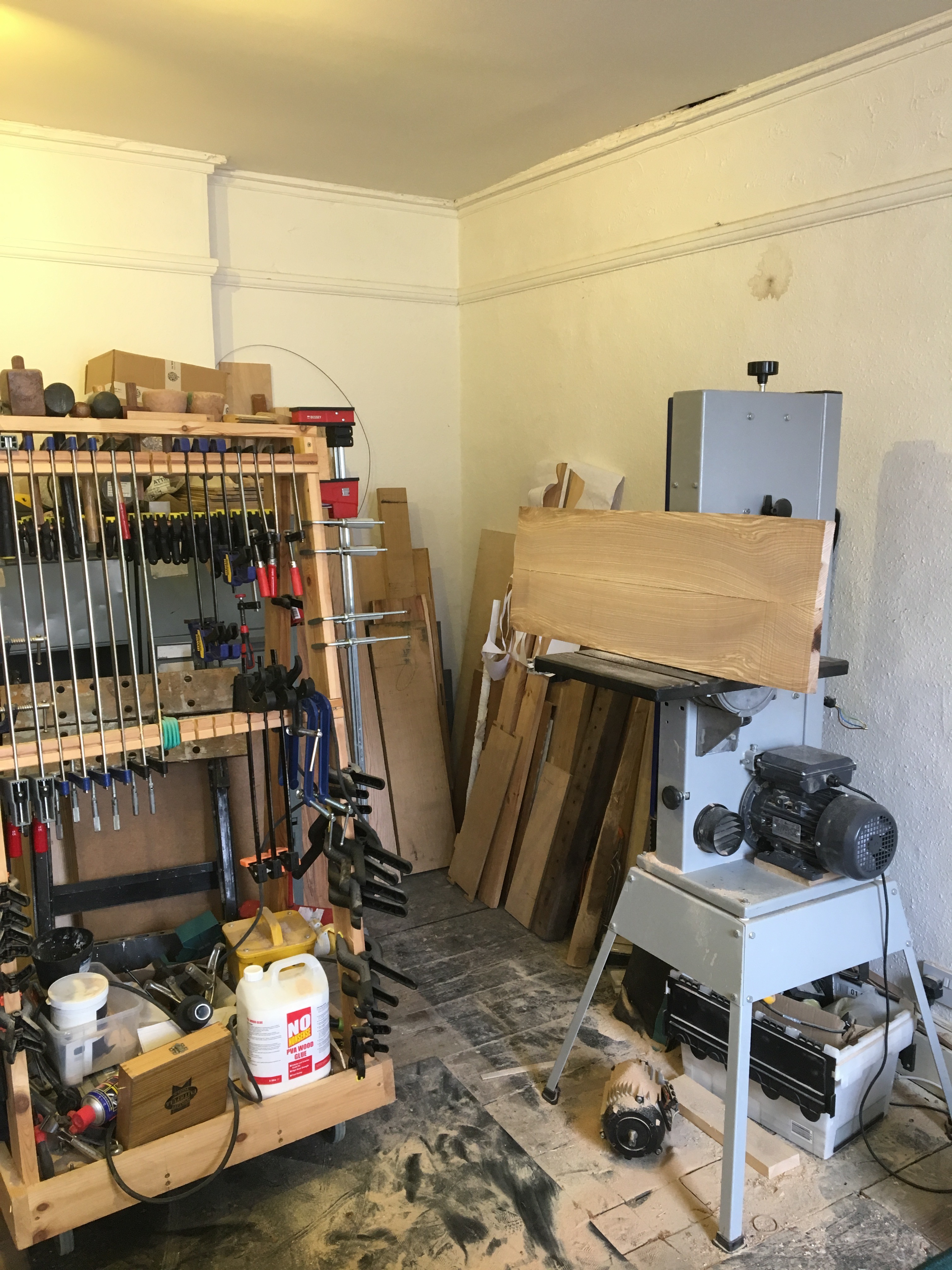
I sourced my timber from a local, family run company near me called Stiles + Bates. They specialise in catering towards wood turners and offer a variety of tools and timber. The Ash I used was air-dried and came from within a 30 mile radius of the saw mill giving the unit a very small carbon footprint.
Stiles + Bates regularly remove trees from churches (primarily Yew), gardens and after storm damage. Although they do also have a wide selection of exotic timber they import.
Tools
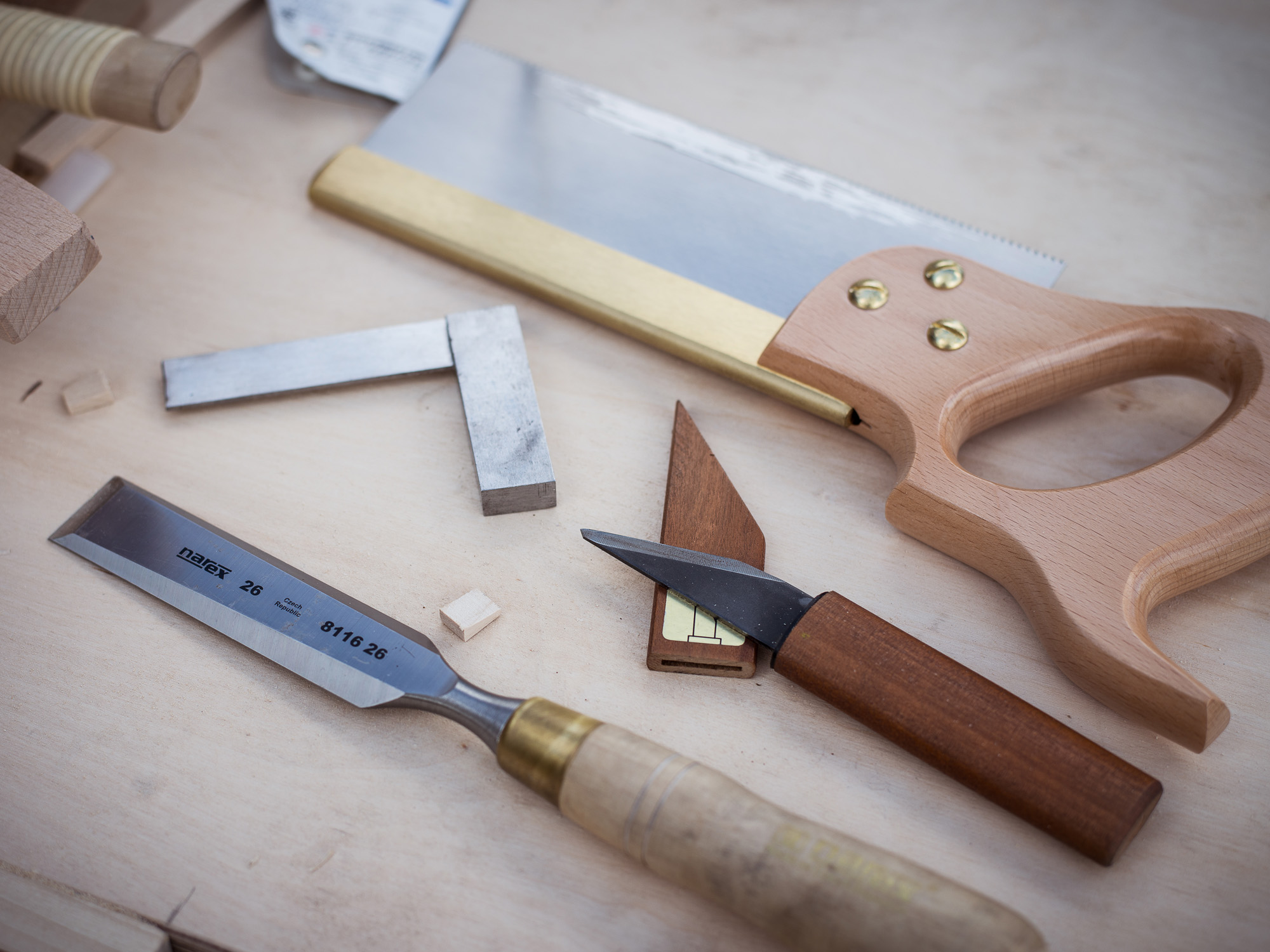
Well I used quite a few but I will be trying to offer alternatives throughout.
- Chisels - 6mm and 20mm or larger
- Mallet
- Jewellers piercing saw
- Scraper
- Marking guage
- Engineers square
- Scalpel/marking knife
- No.5 jack Plane (optional)
- Bandsaw - But in a pinch a jigsaw or even a coping saw would do
- Track saw - you could use a circular saw of even a ryoba Japanese saw in it's place
- Surface Planer (known as a jointer in the US) - Optional
- Thicknesser (known as a planer in the US, confusing I know) - Optional
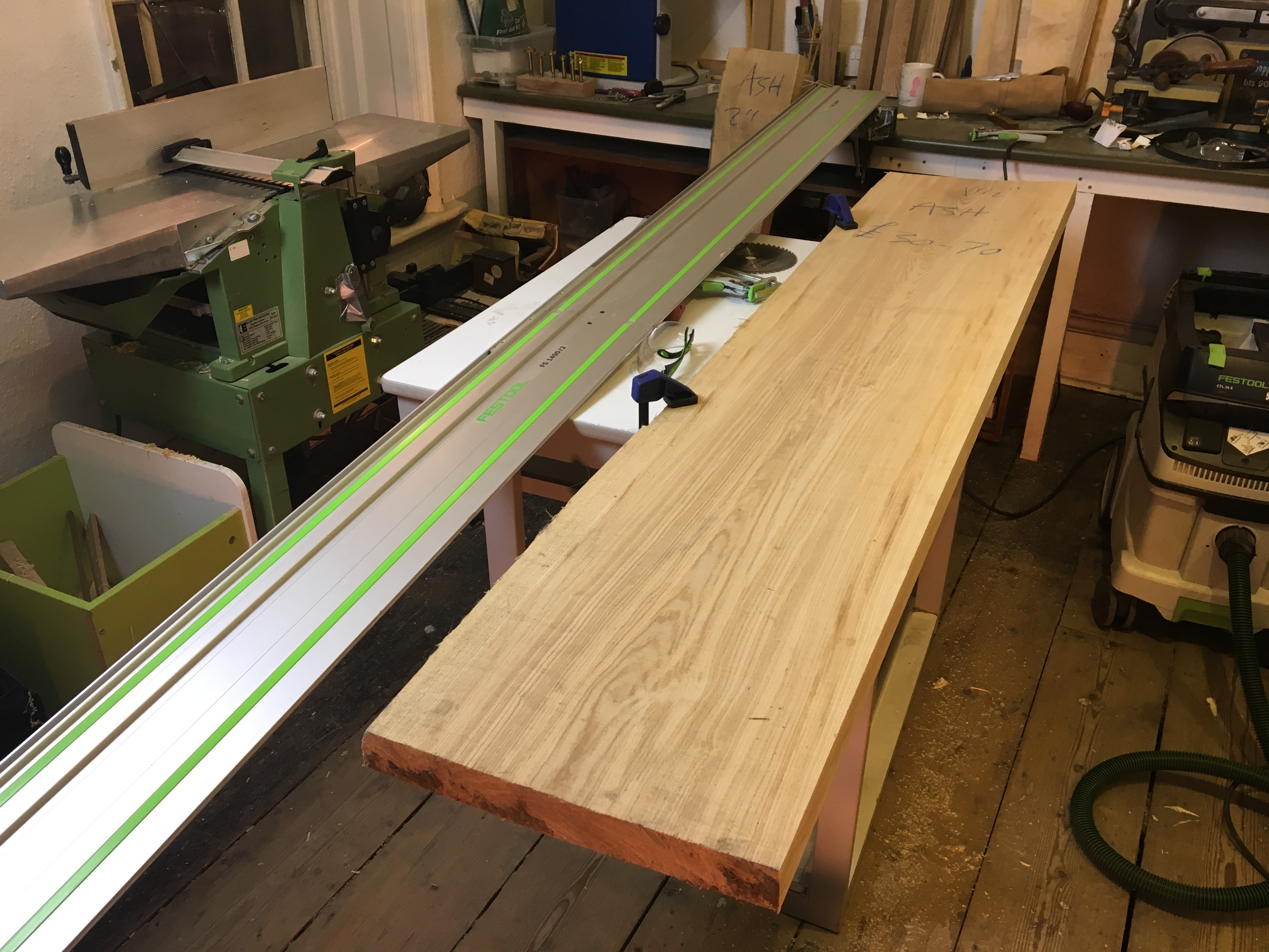
Ripping (optional)
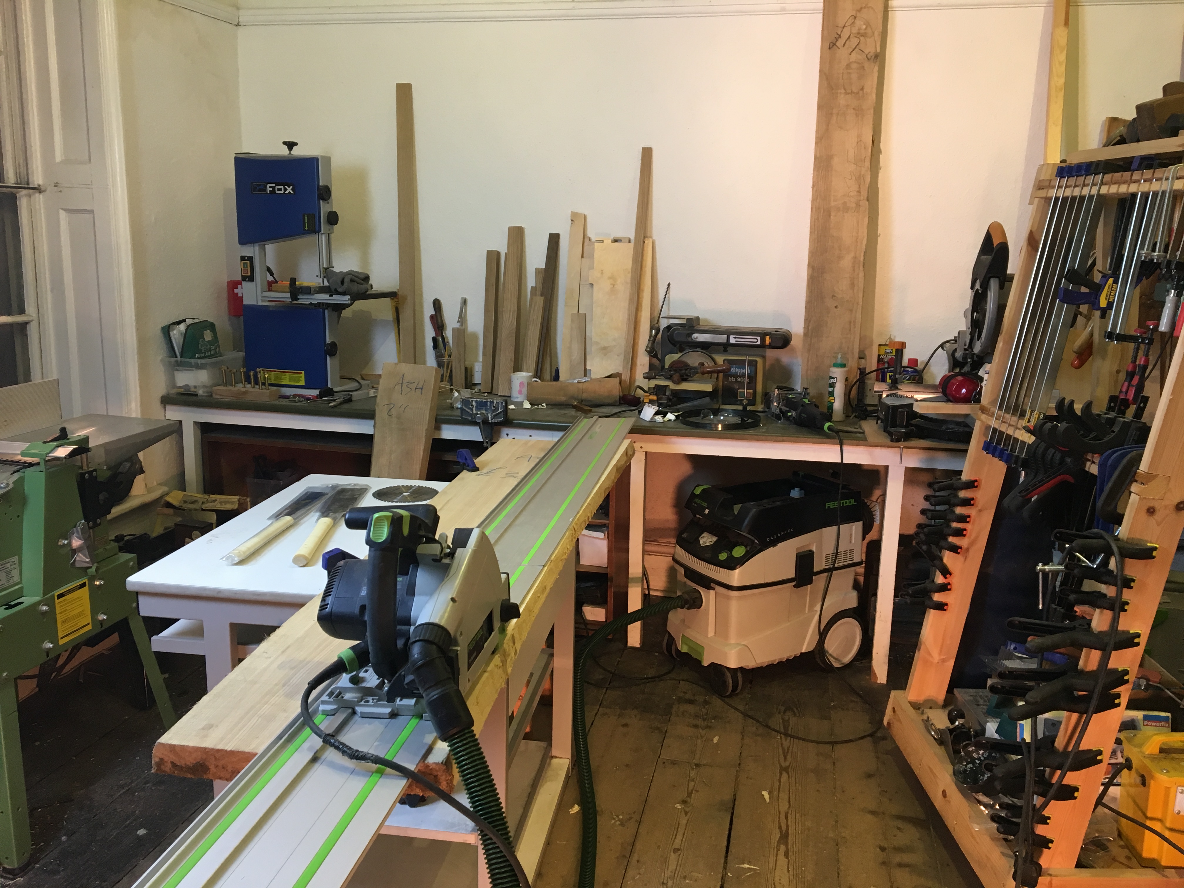
If you are paying for the timber yard to prepare the materials for you you will not need this step.
After selecting my boards from the timber yard I ripped them to width using my track saw. When ripping timber it is a good idea to use a rip cut blade, these have fewer teeth than crosscut blades and cause less stress on your saw.
As an example my crosscut balde as 52tpi (teeth per inch) and my rip blade has 8tpi. In a pinch a crosscut balde will still work just go slow and don't think of it as a long term solution.
Note:
If you don't have a track saw you can do this step with either a circular saw, table saw, bandsaw or hand saw. For a hand saw I recommend a ryoba saw. I still use my ryoba every week or saw as it is my most versatile hand saw.
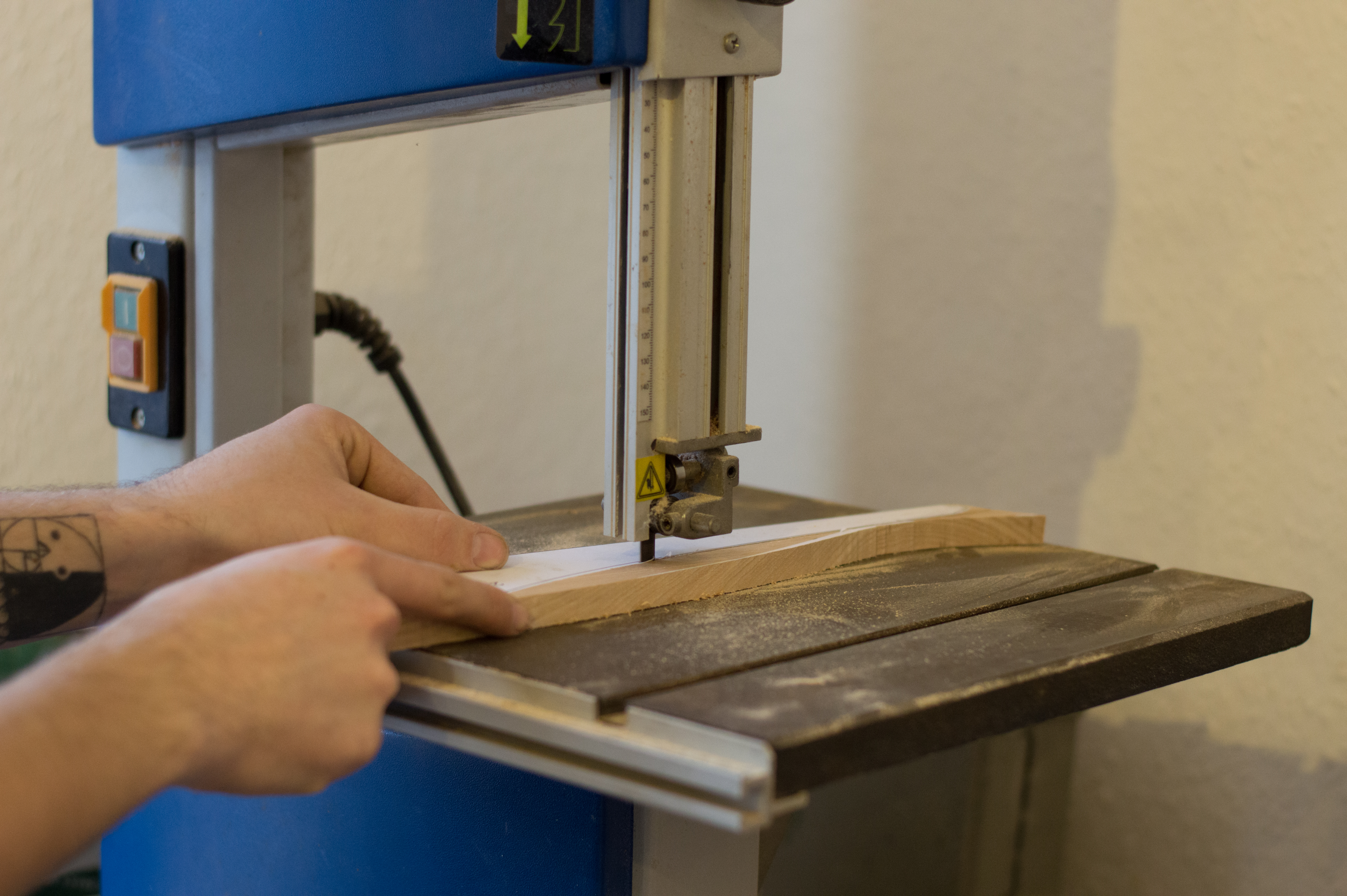
Re- Sawing (optional)
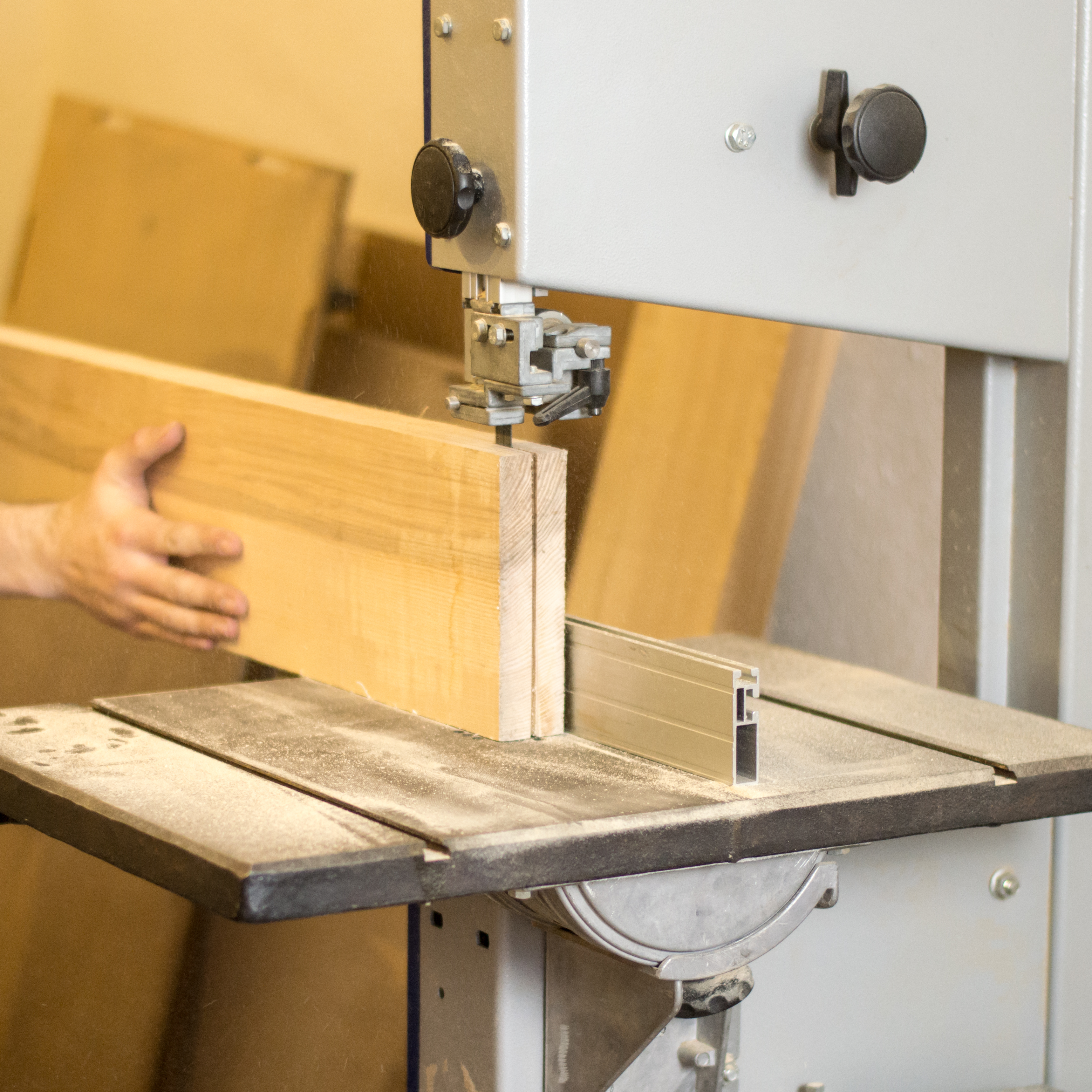
I wanted a book matched top* for my cabinet so I ripped my timber down it's length as shown above. When ripping timber on a bandsaw you need a low tpi blade. I recommend a 3 tpi 'hook-tooth' blade that is at least 3/4 of an inch in width.
The lower tpi stops the blade becoming clogged and clears waste more efficiently. The wider the blade the less wander (side to side movement of the blade).
You also want at least a 1kw motor to make rips this large (165mm or around 6").
* book matching refers to cutting a board in half and opening it like a book. It is a decorative feature that serves no real structural benefit.
Surface Planing and Thicknessing
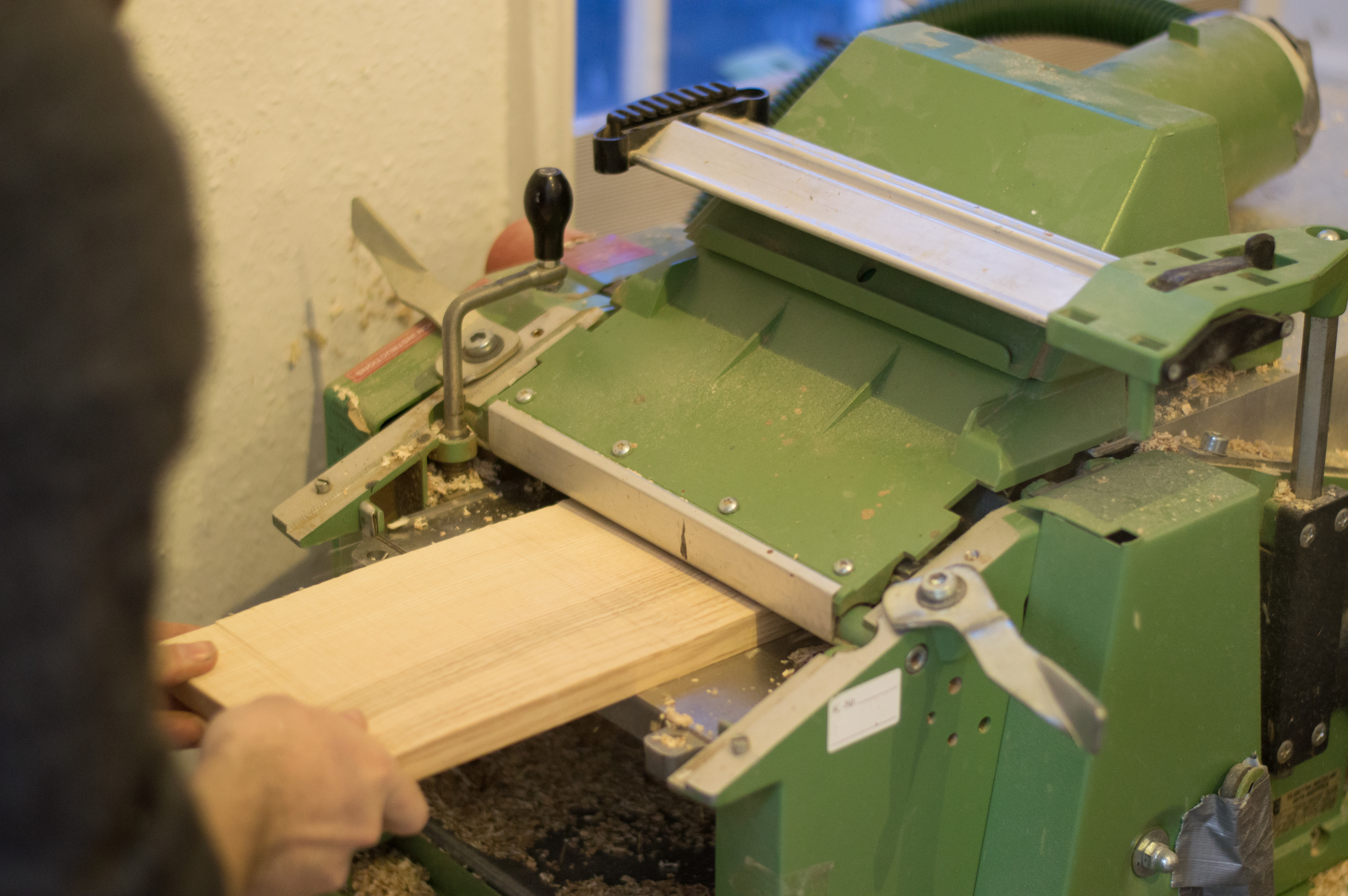
When you buy a board from a timber yard they are normally stored rough-sawn. This is because timber moves constantly as it dries. You want all the major movement to be done prior to being made to final dimensions.
Buying timber rough saw allows you to save a huge mount of money over the long term. This is because you do not have to pay the timber yard to prepare your timber. I save about 40% overall from prepping timber myself. This being said you do need fairly large, heavy equipment to do this that does require some training to operate and regular maintenance.
So it comes down to a simple choice, how much wood do you buy?
Joining Boards
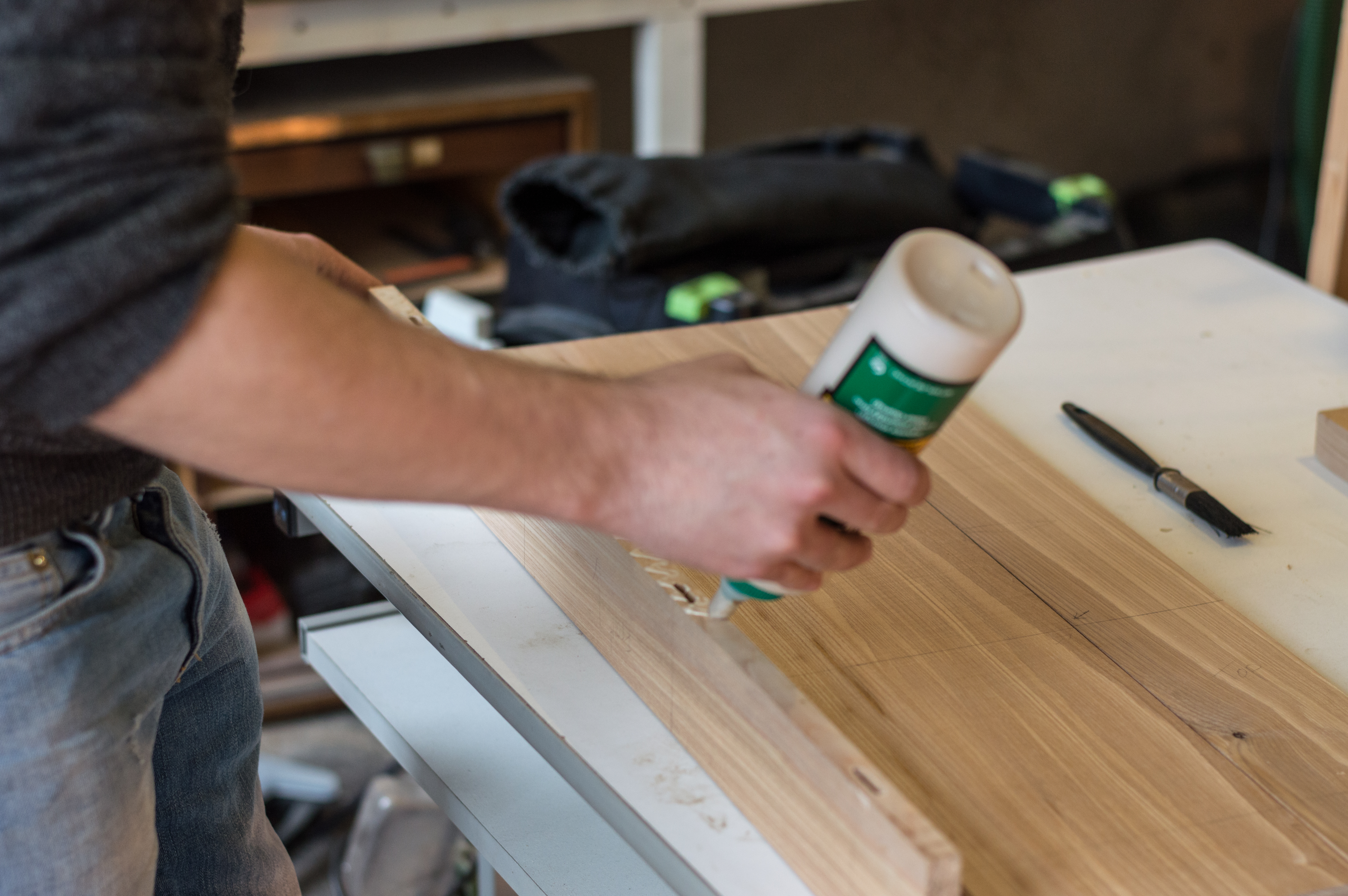
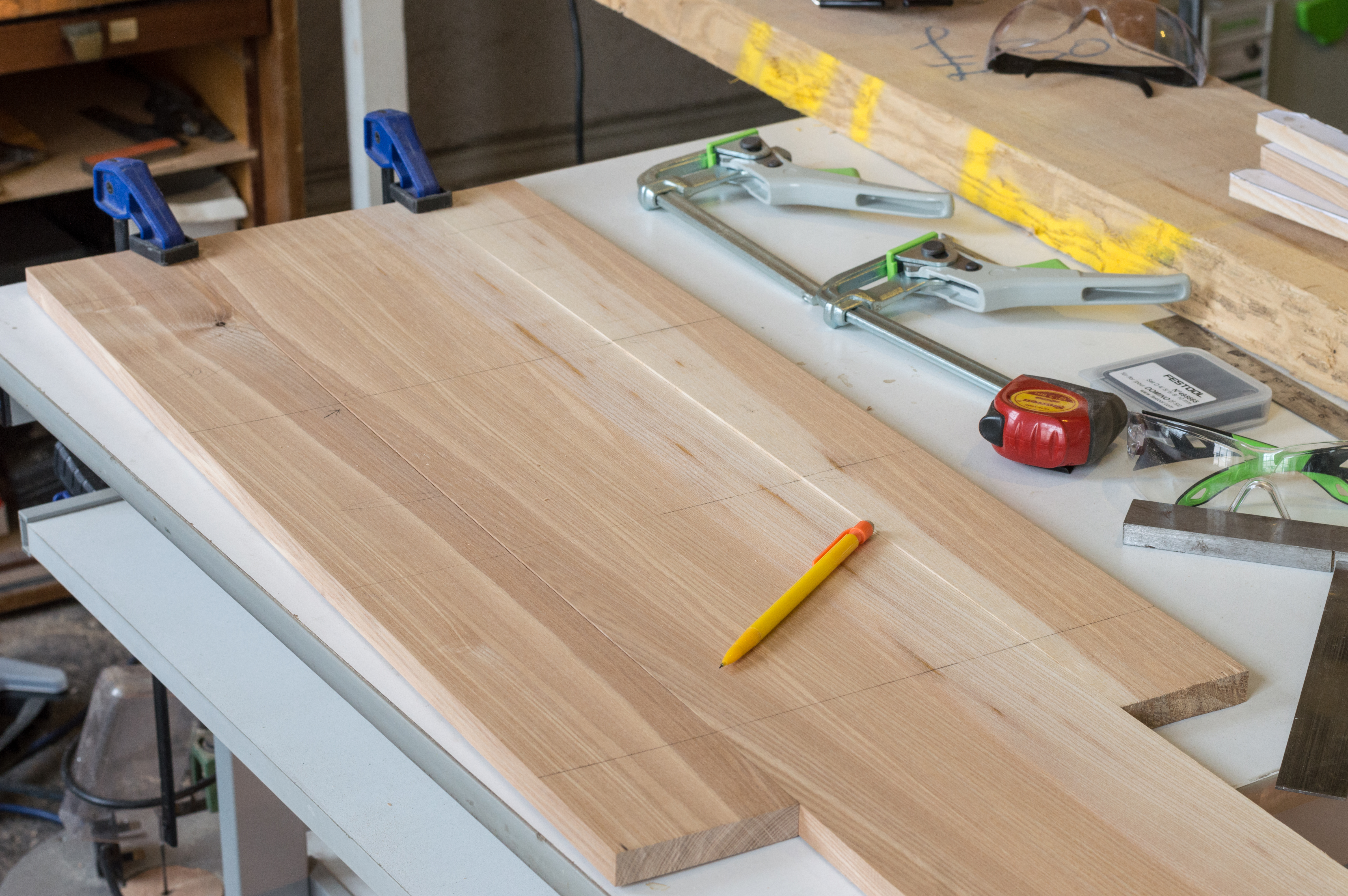
Now when you make a solid wood cabinet it is rare to find a board that is as wide as you require. As well as this, even if you did it's not a great idea to use single boards over 150mm in thin boards.
To keep timber stable it is good to glue multiple pieces together with opposing grain (smiley face to sad face).
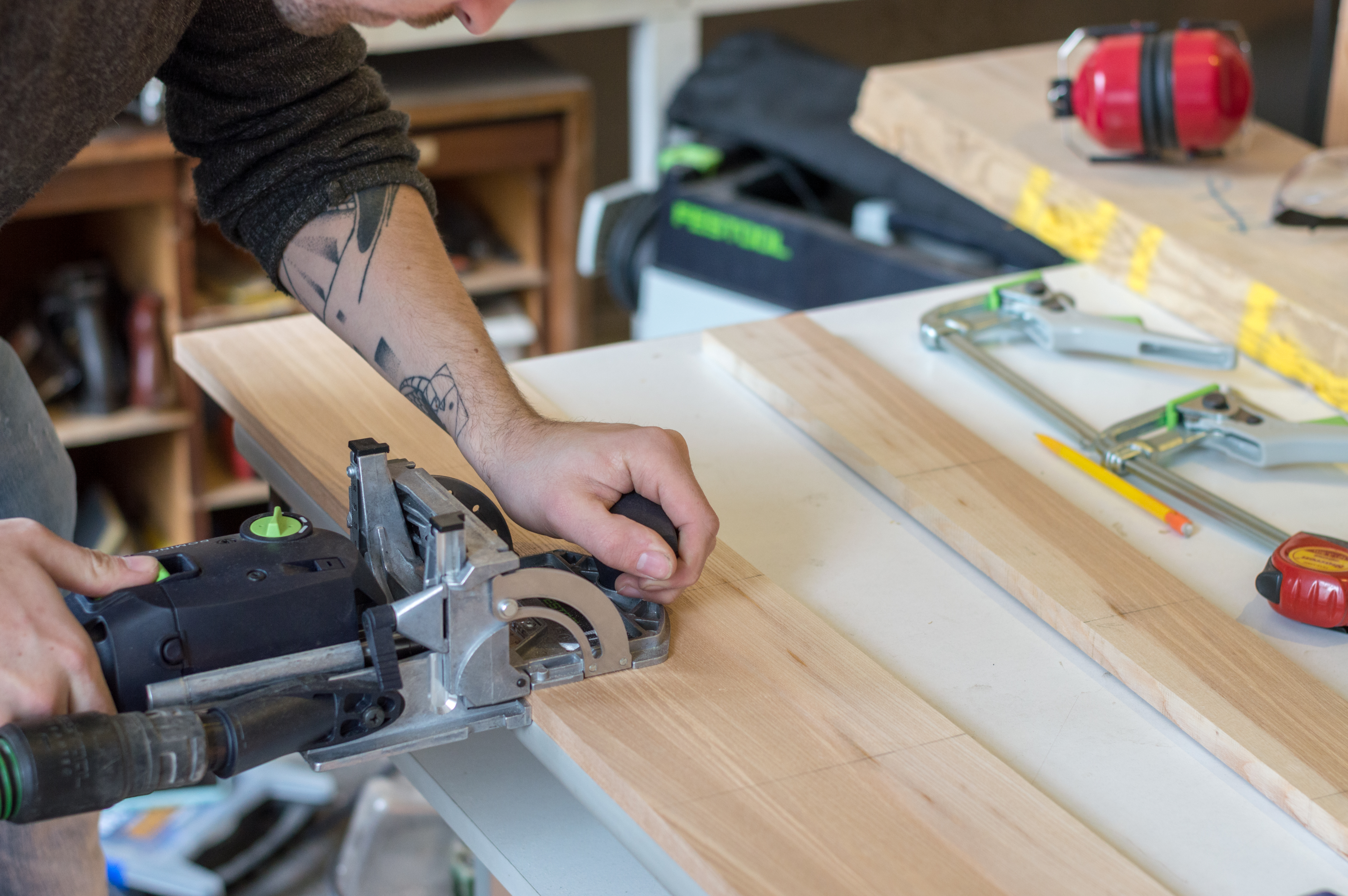
Note:
I used a domino jointer to keep pieces aligned while gluing up, this is not a necessary step, it just makes life easier.
Templates
So here's a link to the template file you will need to cut the front ribs. The file is full size vector so you can cut them out on a CNC or laser cutter or just print them at your local printers as I did.
If anyone has any problems with file types let me know in the comments and I will adjust them accordingly and put in new links.
Here's the link .
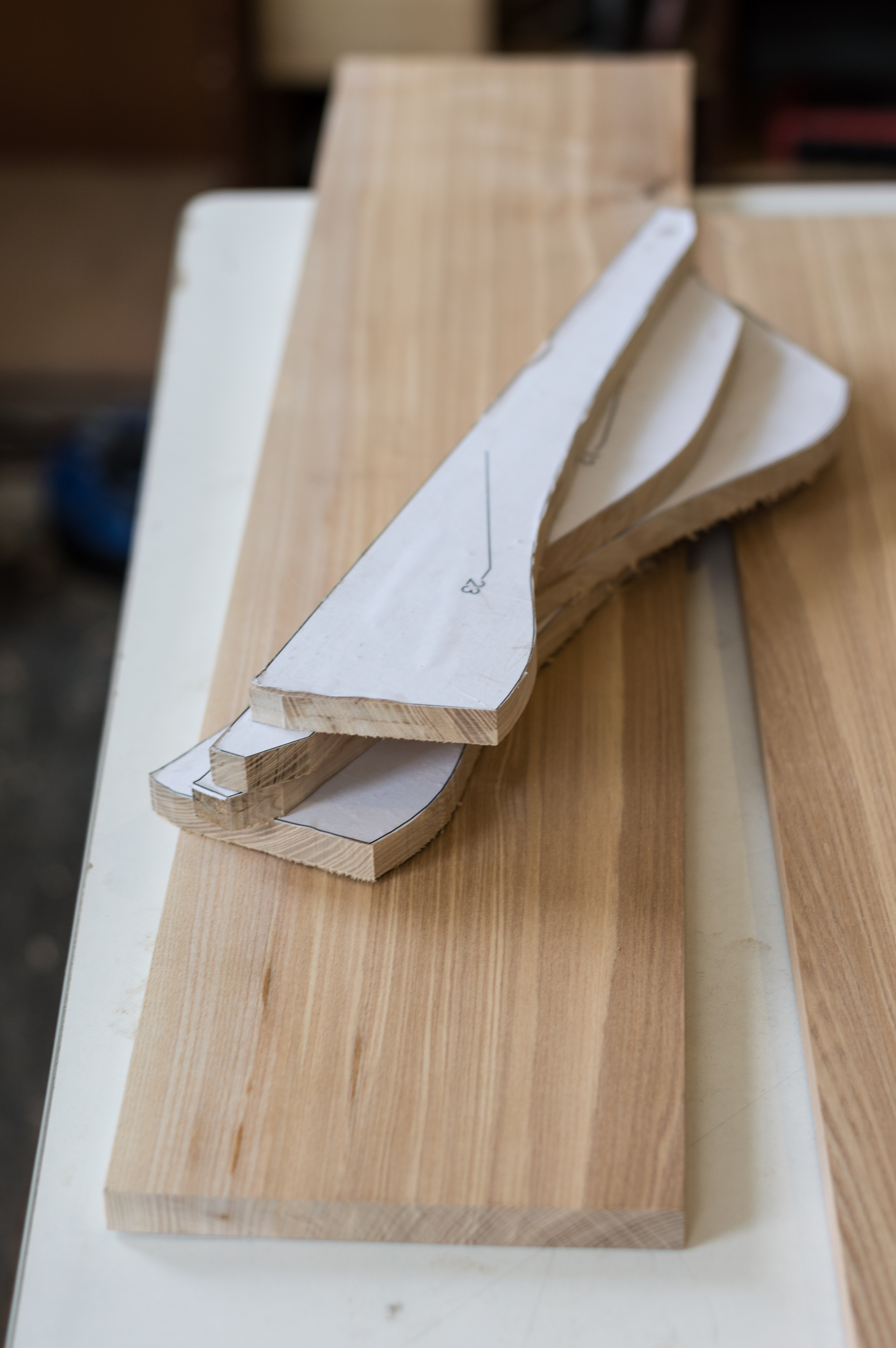
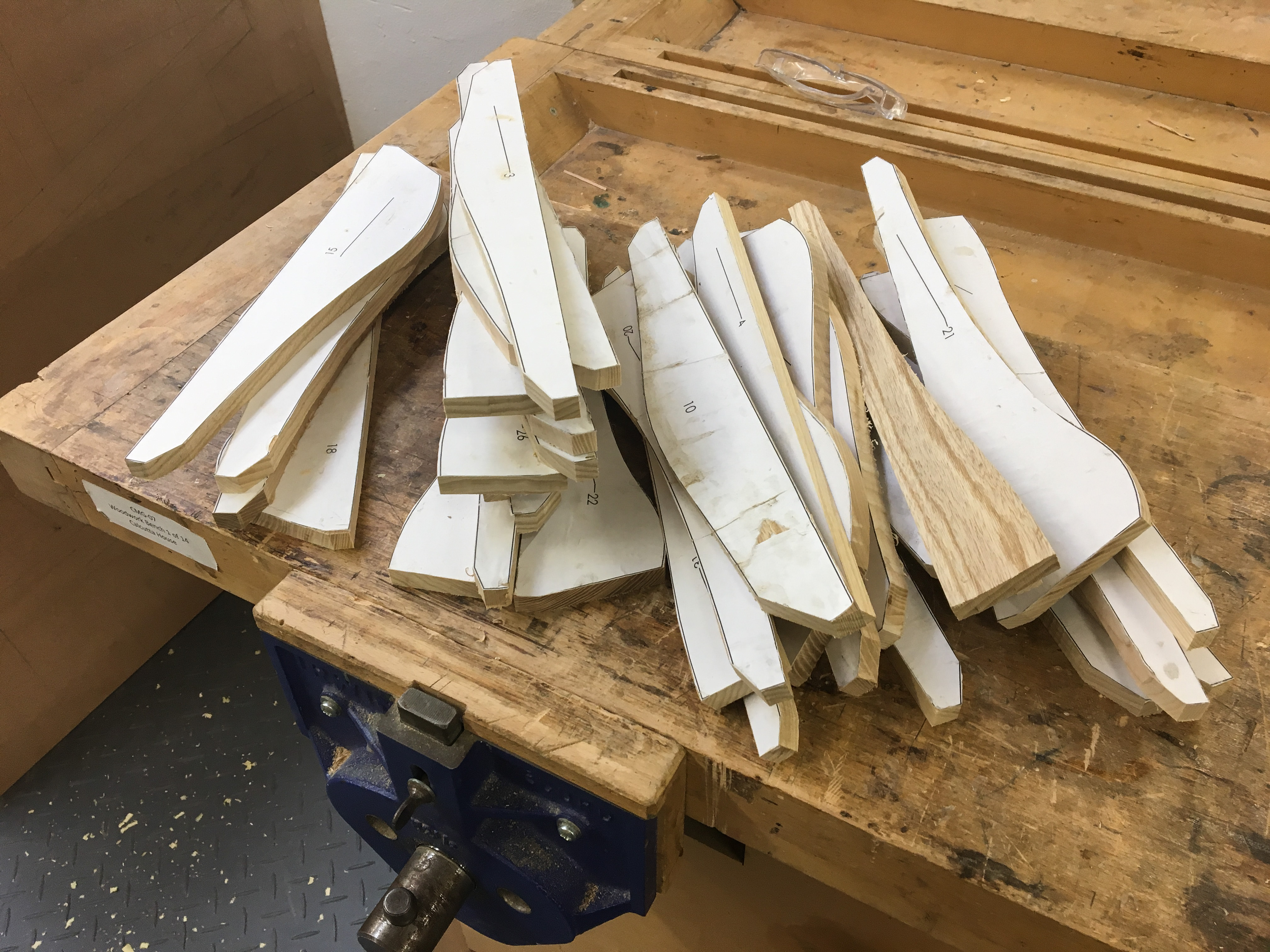
Gluing Templates
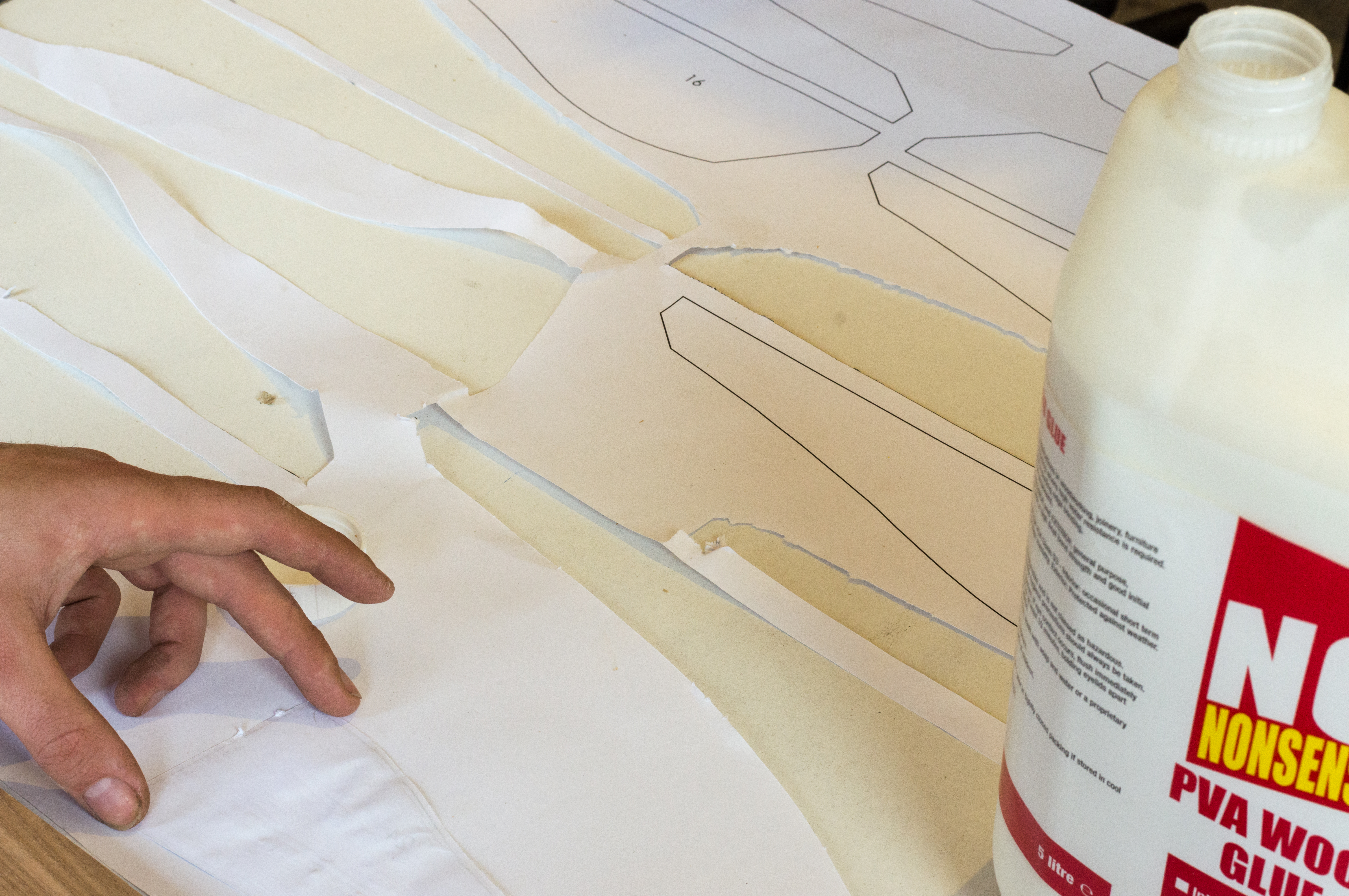
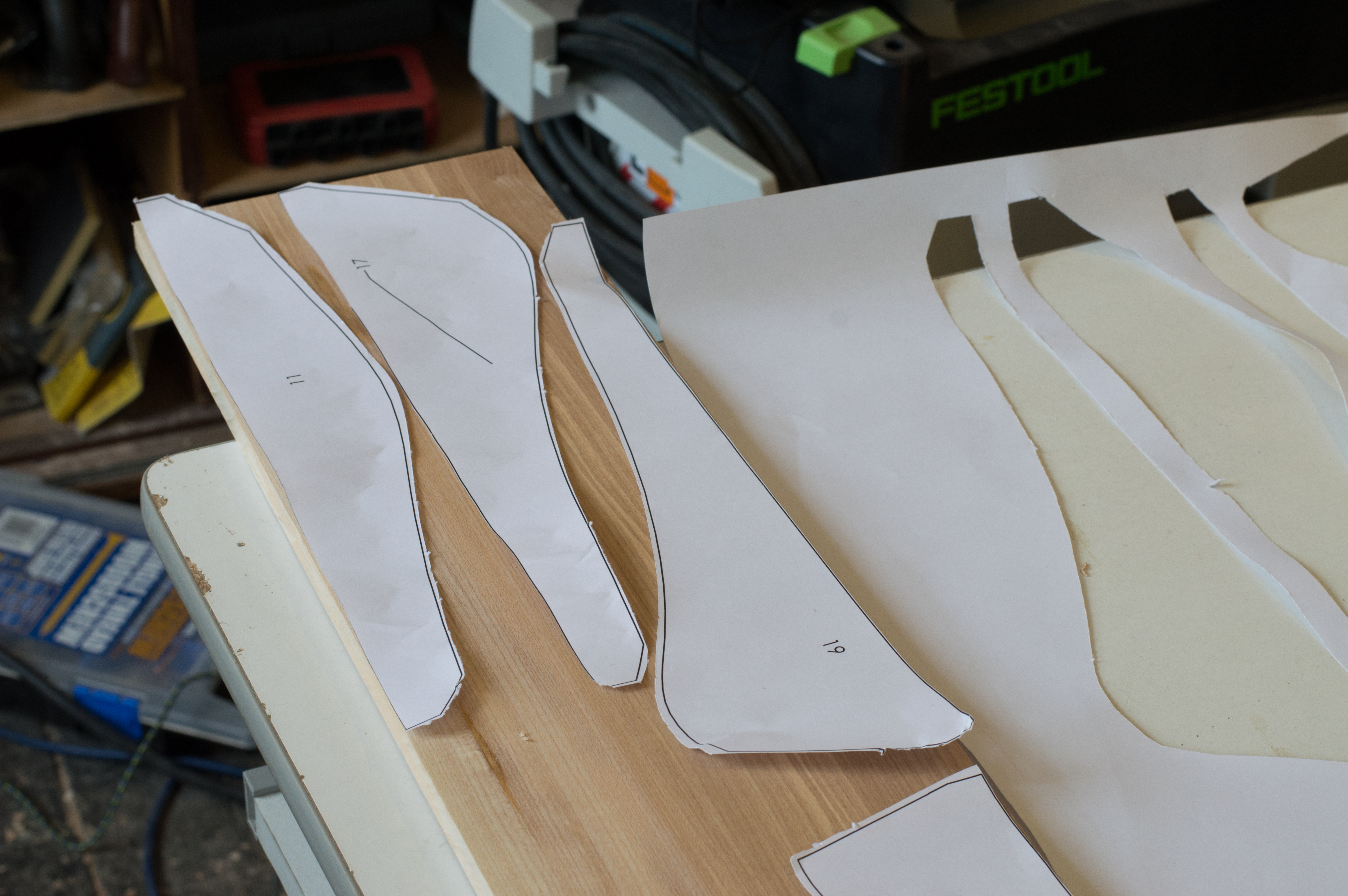
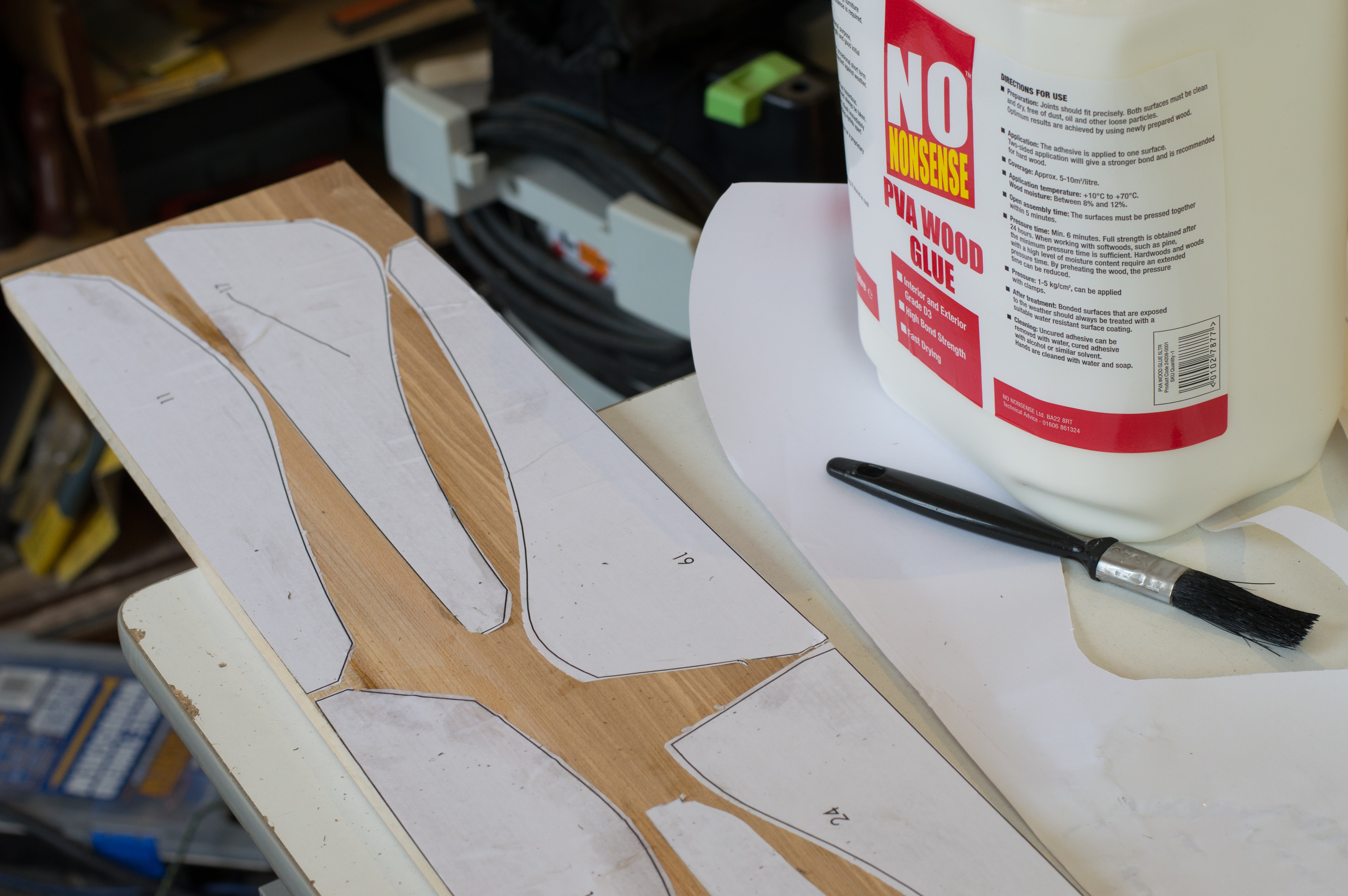
So when it came time to cut the ribs/slats for my cabinet I went to a local printer and had my templates printed 1:1 size.
I then attached them to my boards using PVA glue but from what I've read spray mount would actually have been better. If you have a CNC this would be a great time to use it and it's how I would do it if I was making one again and... had a CNC.
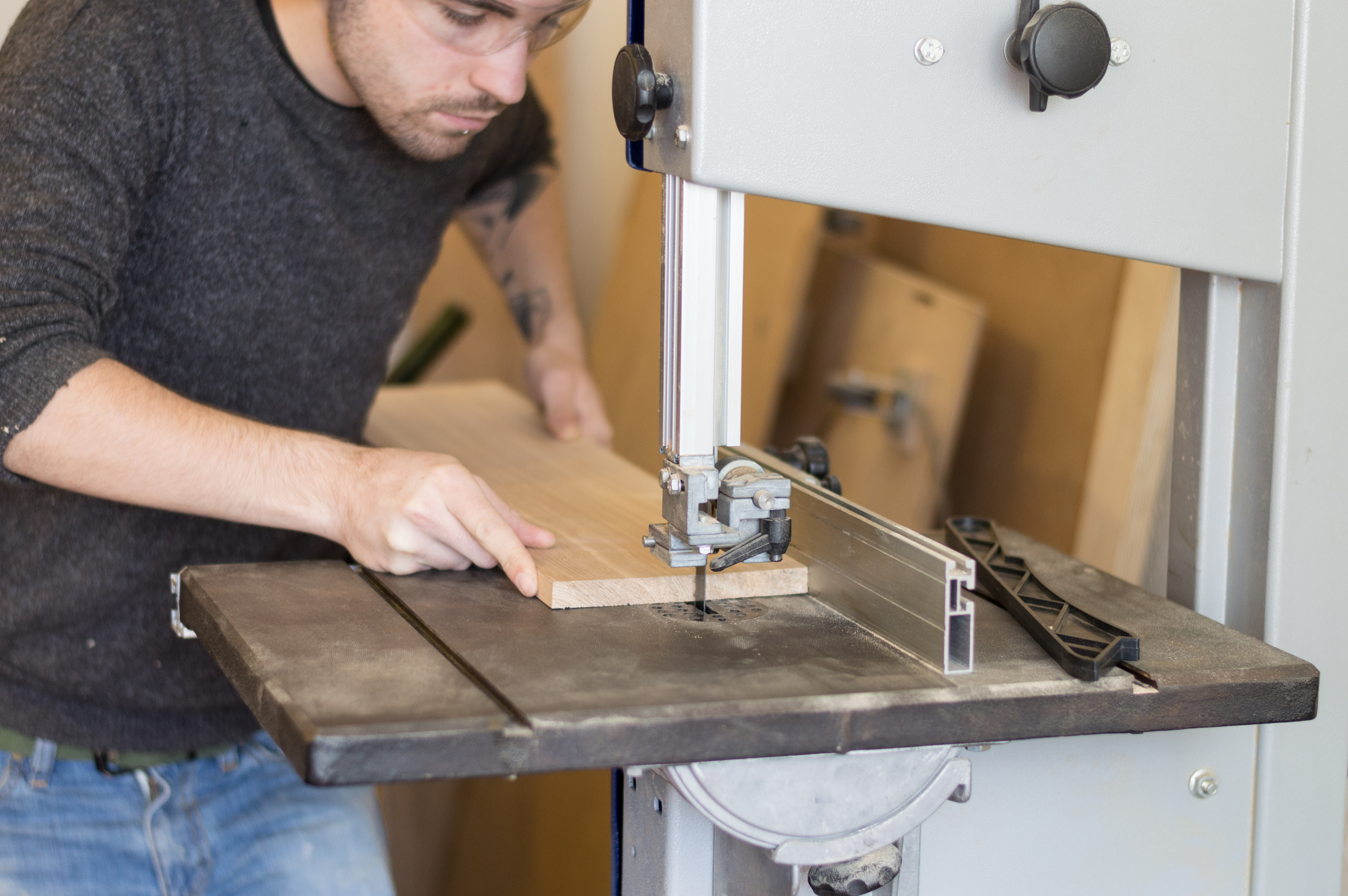
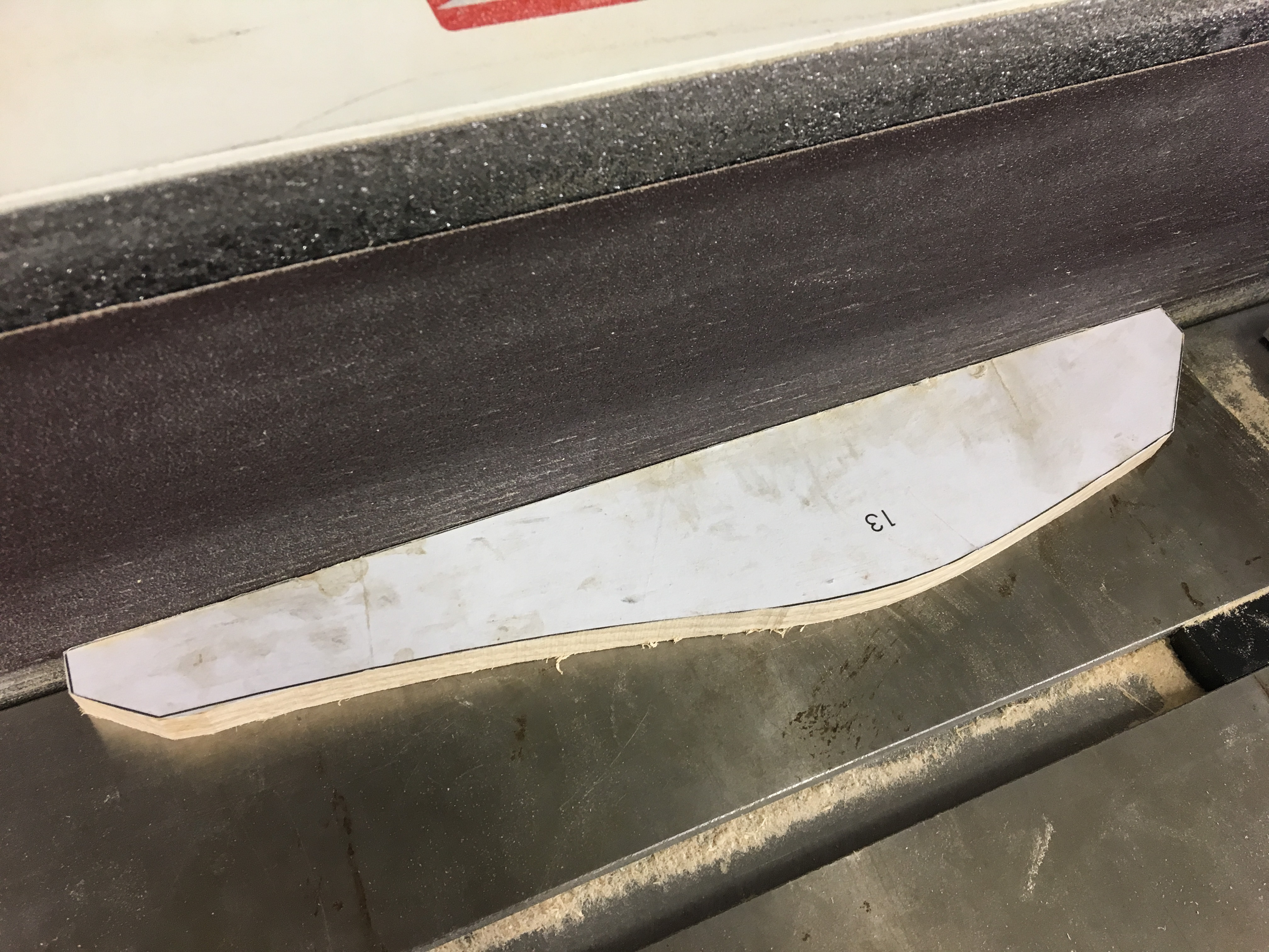
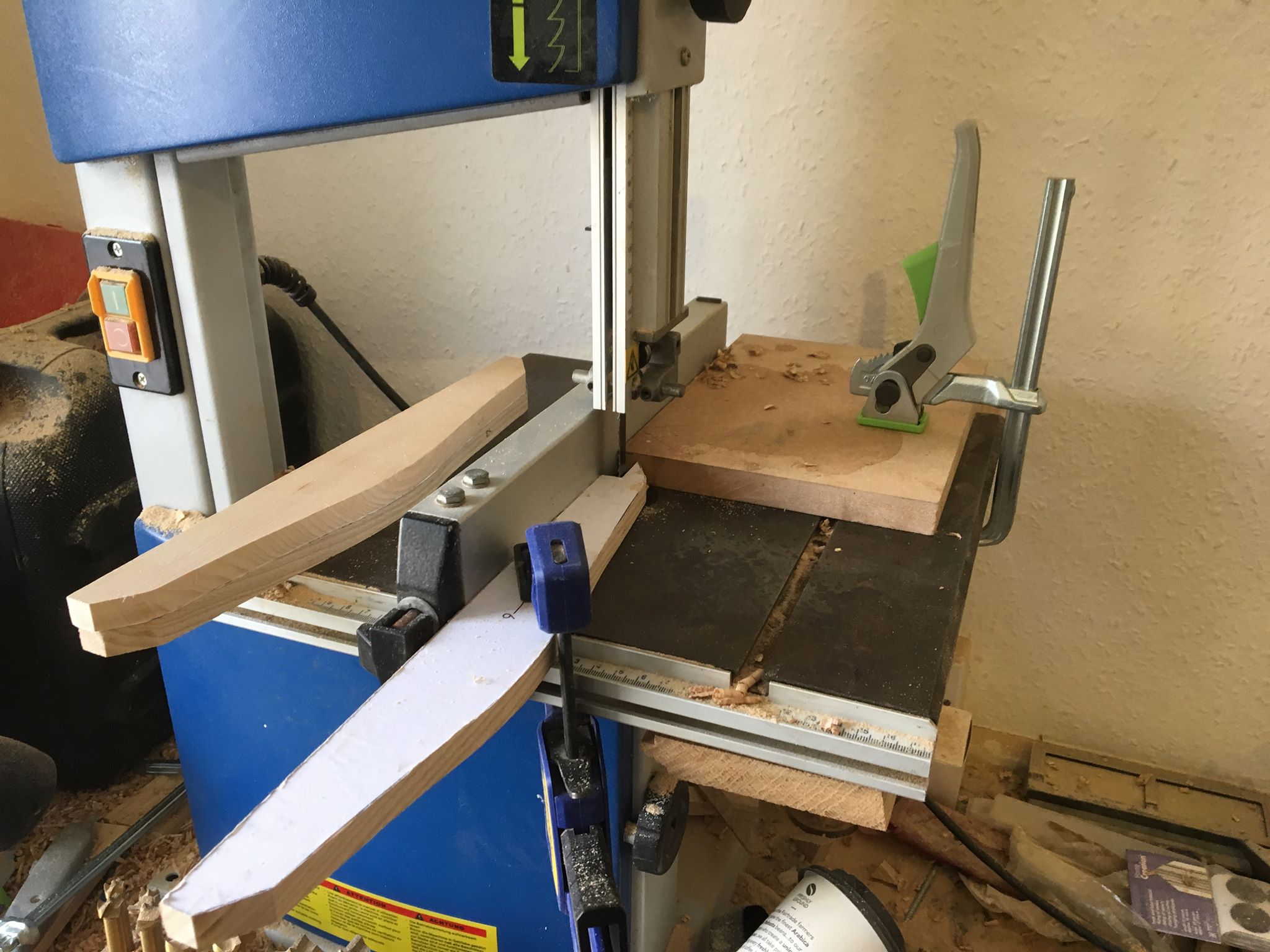
Cutting the Front
To cut the curves it's a good idea to use a nice narrow blade on the bandsaw, the wider the blade the less sharp the turns you can make.
If you do not have a bandsaw i found you can make these pieces with a scroll saw, jig saw and even a coping saw.
Getting Somewhere
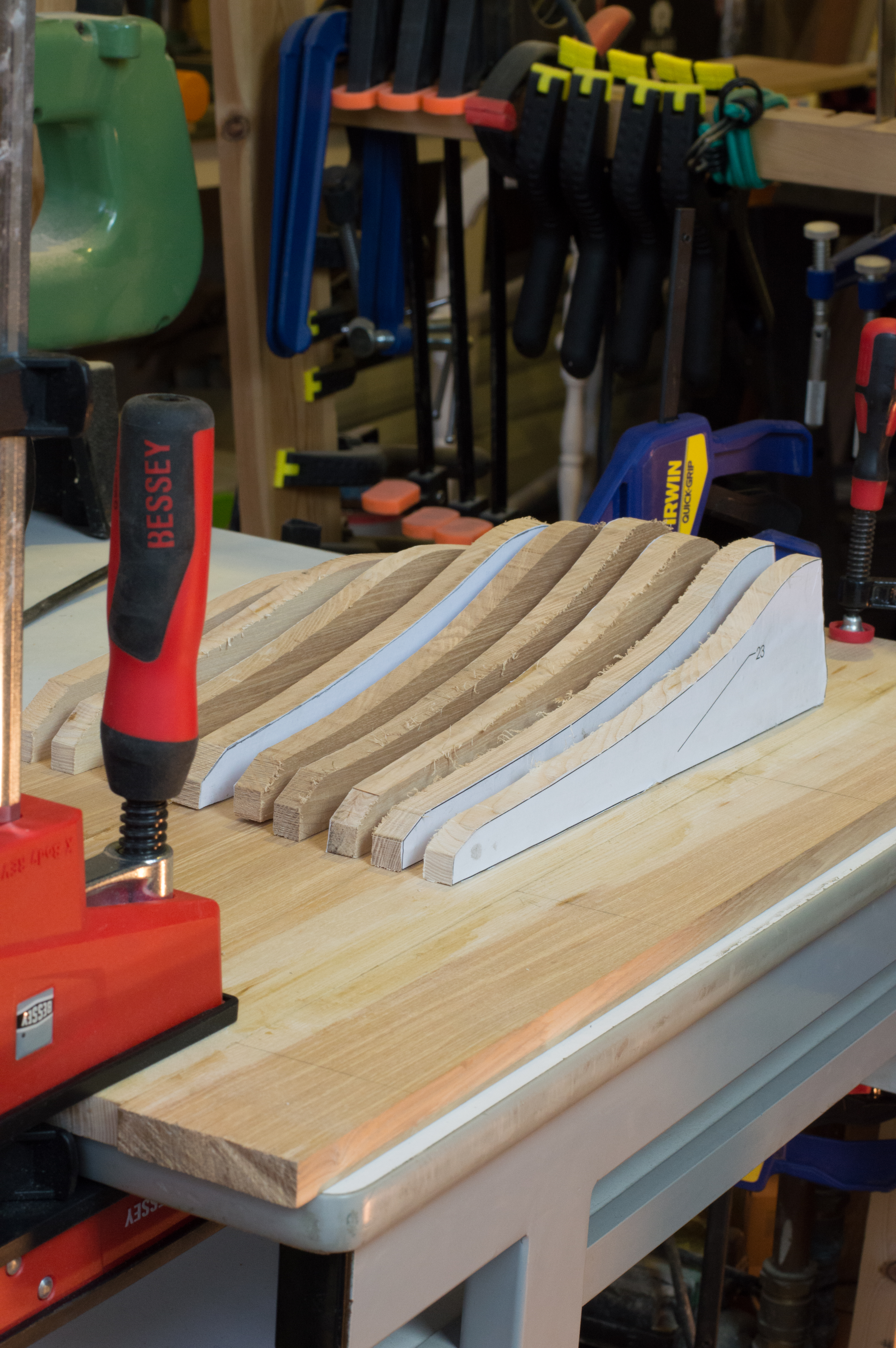
Yes there are lots of them!
It's Sanding Time
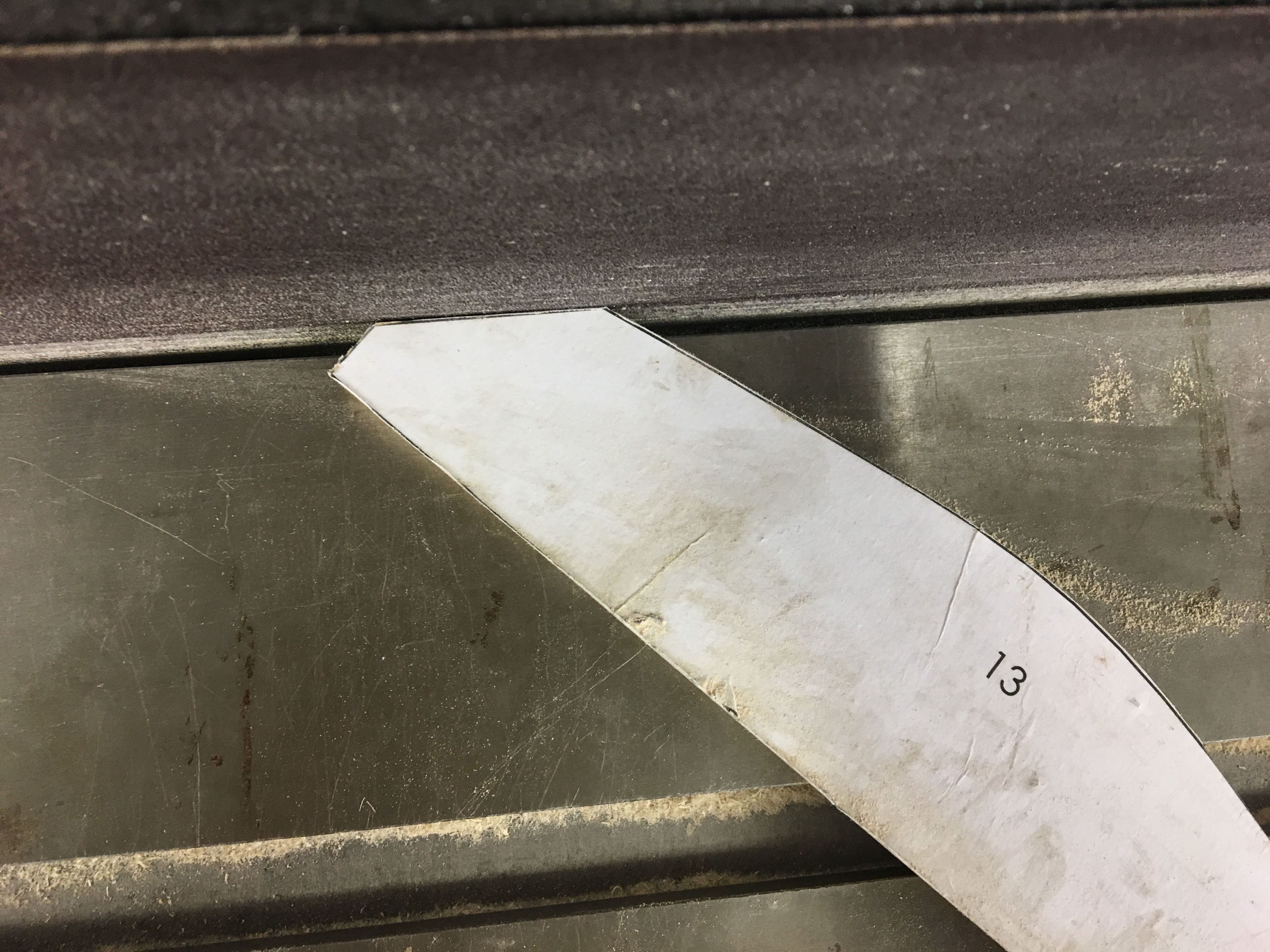
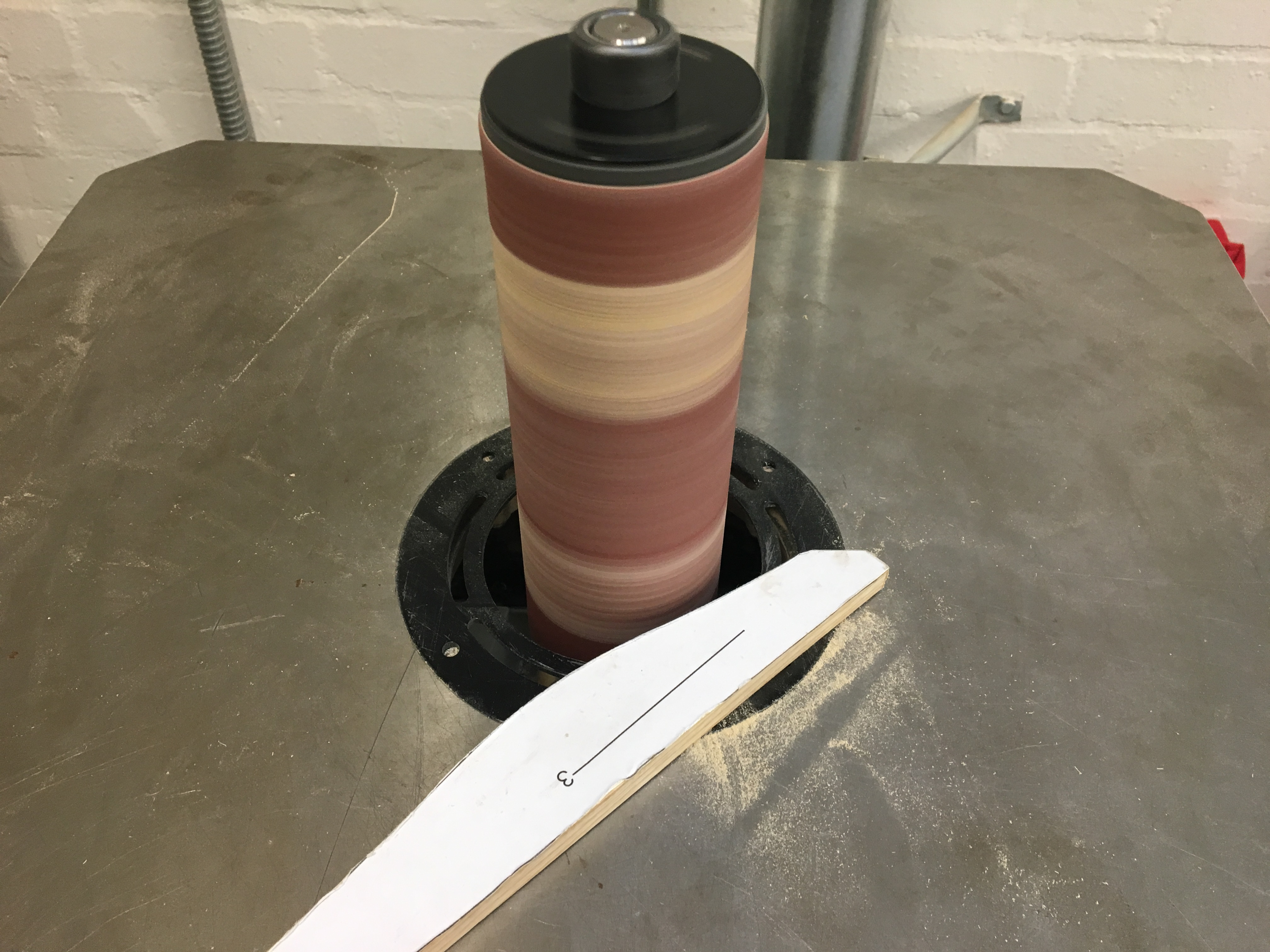

Found my way into a proper workshop today! this meant I could save some time and sand the pieces on a few fancy sanders. I used a oscillating edge sander and a oscillating bobbin sander.
Of course you can sand all these pieces by hand.
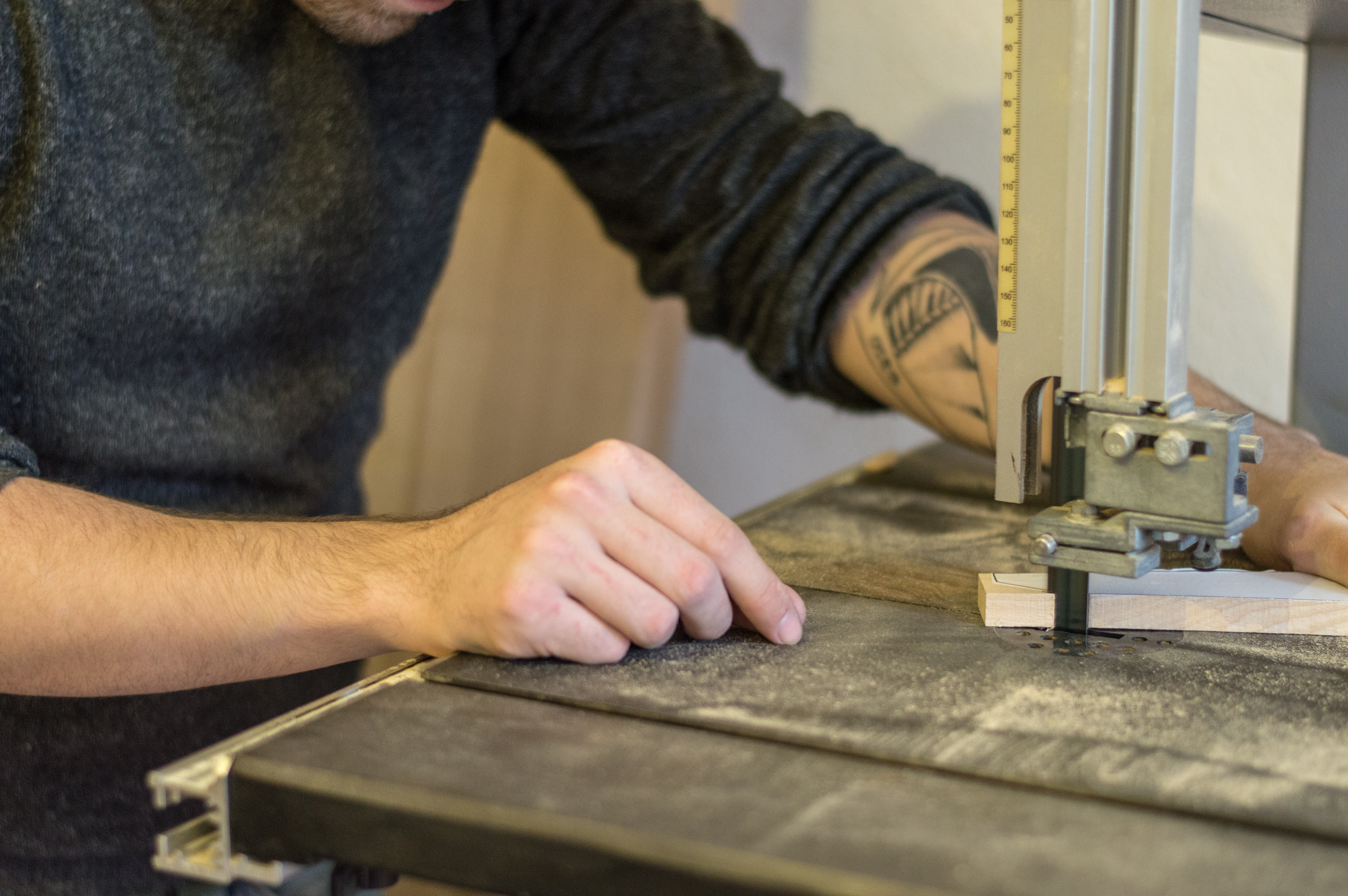
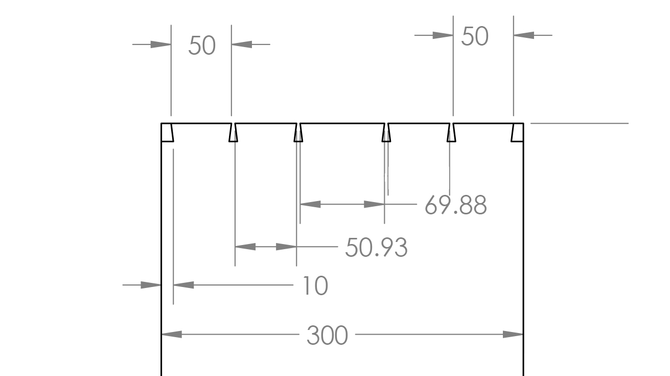
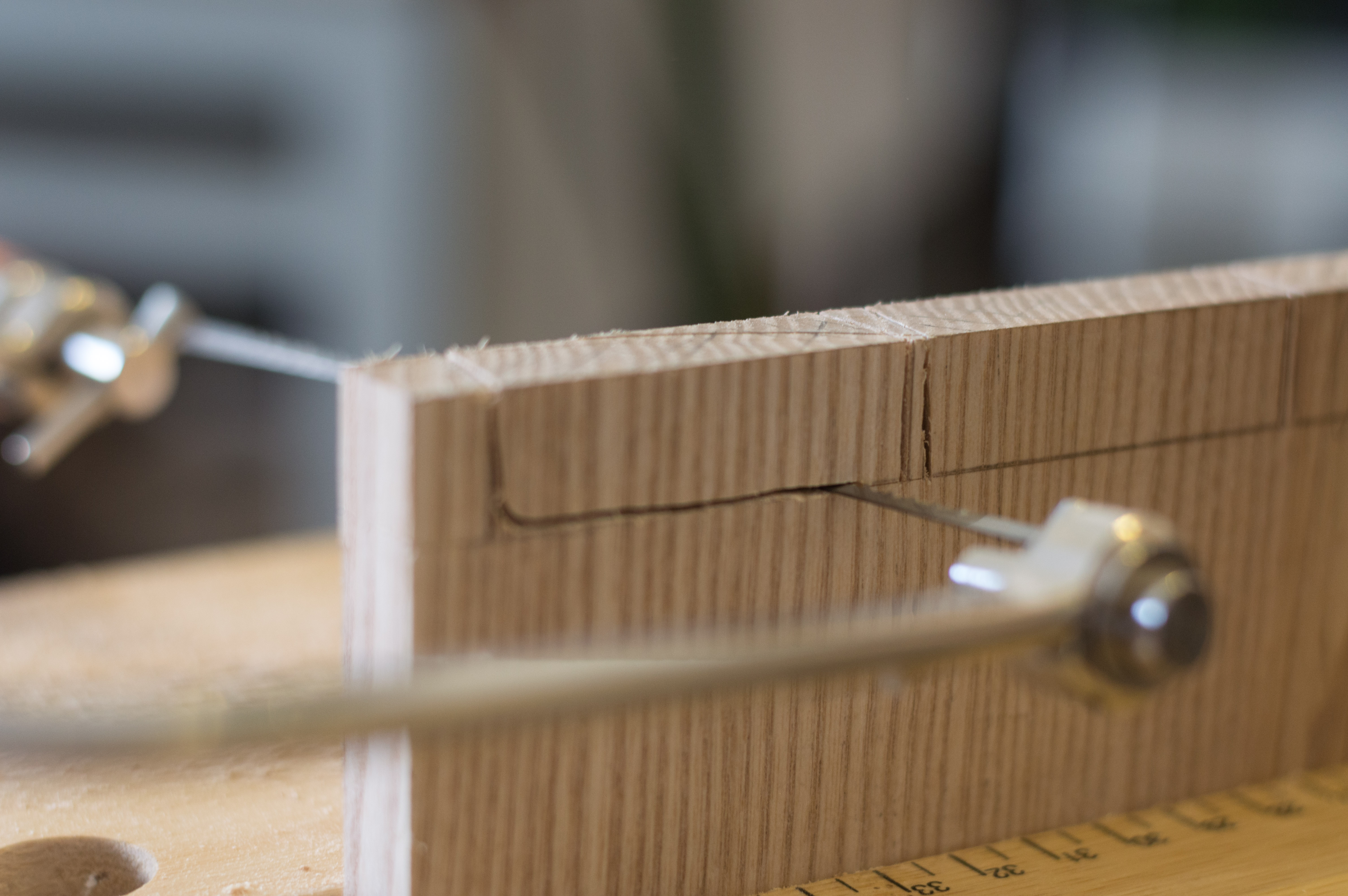
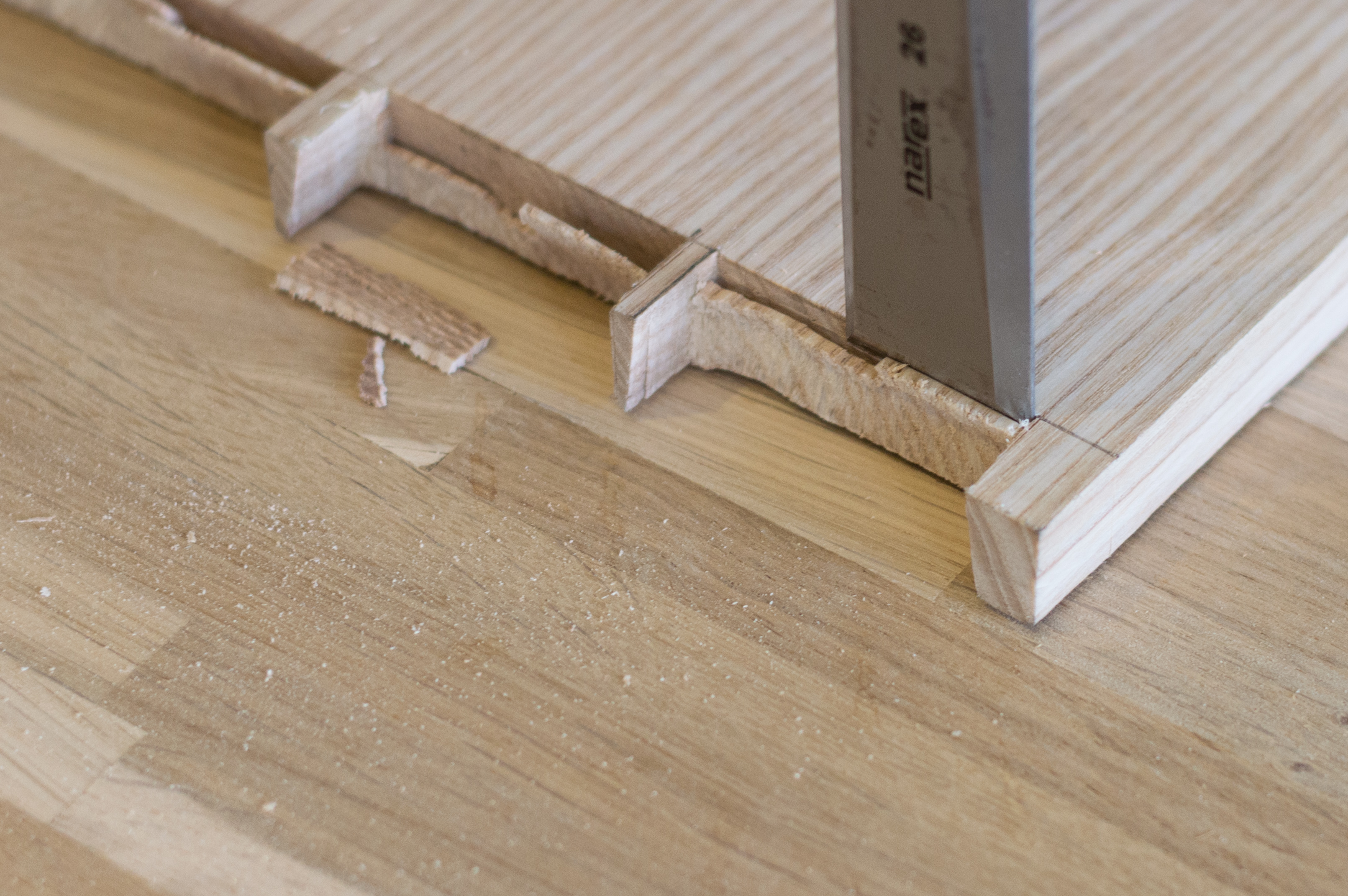
Notches
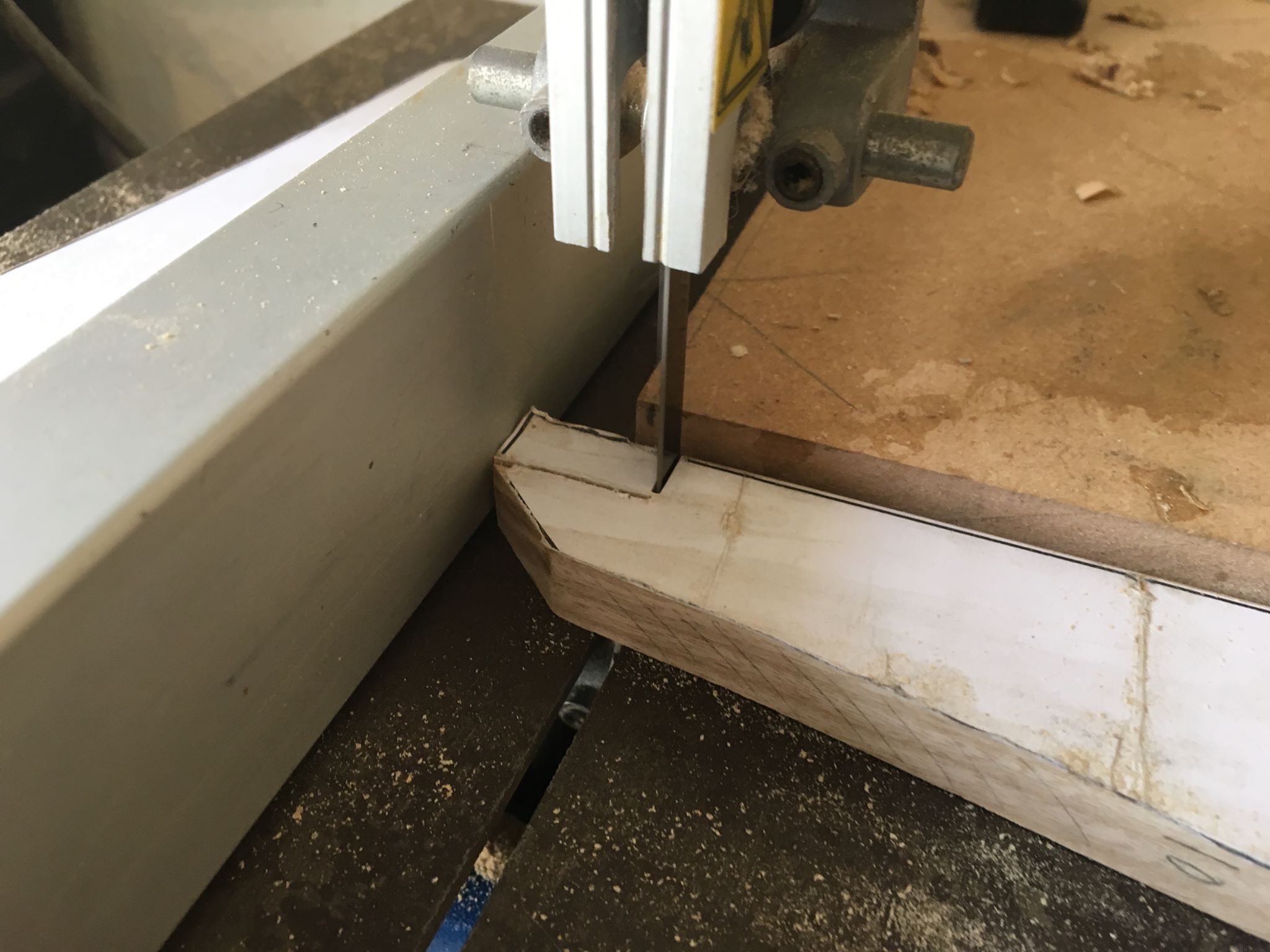
To cut the notches I clamped a scrap of MDF with two square edges on my bandsaw table as depth stops and set the fence accordingly.
Planing and Scraping... Fancy...
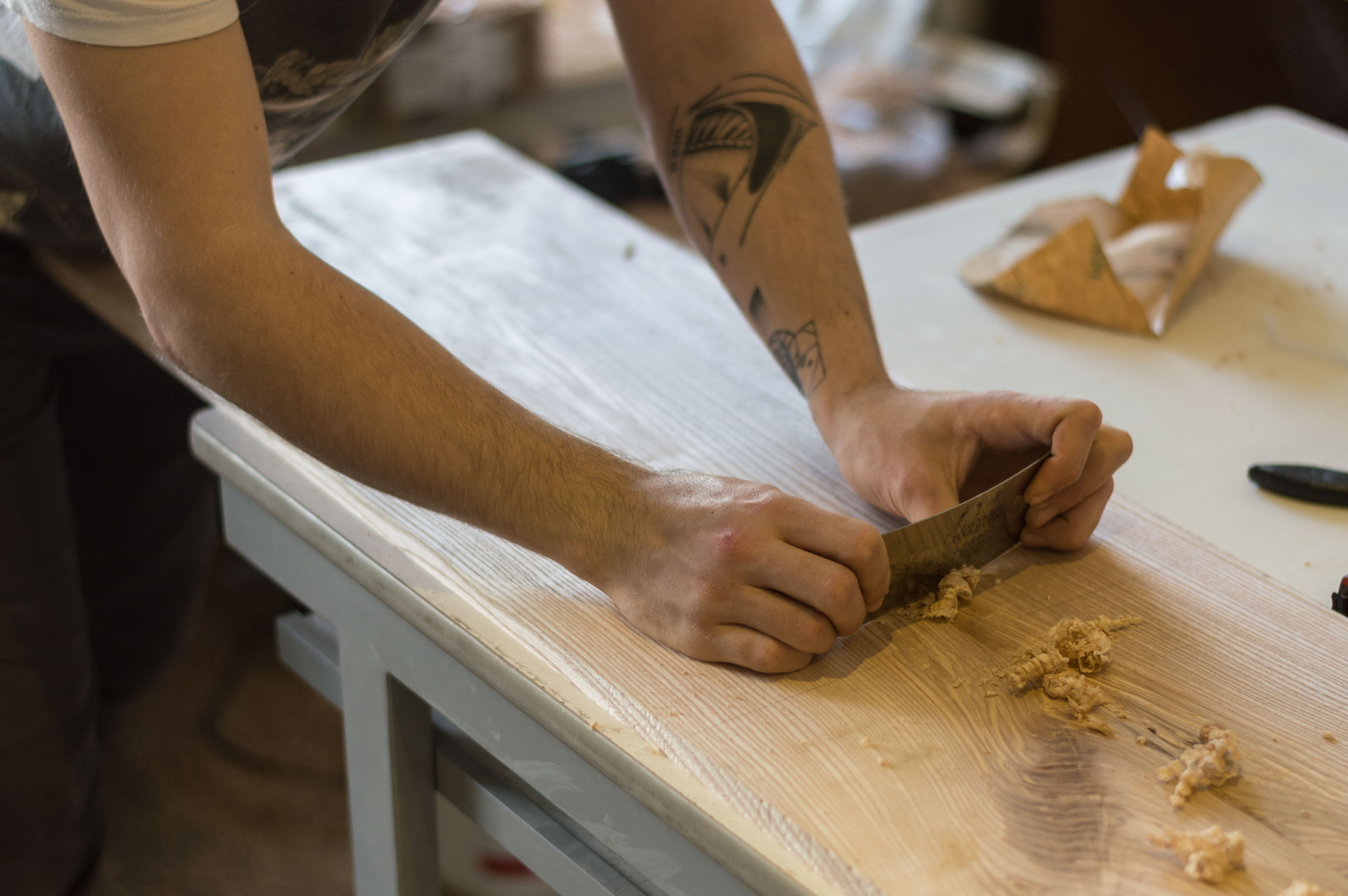
So I used a lot of rift sawn Ash in this project for aesthetic reasons. The problem with rift sawn Ash is that it is fairly prone to tearout, nothing like cherry but still likely. To remove tearout you can use a drum sander, which is in my view the best option. Otherwise if like me you don't own a drum sander you can use a card scraper or hand plane.
Card scrapers are great because they are very cheap and very easy to sharpen. You stick one in the vice and burnish the edge using a piece of round hardened steel. This could be a burnisher or even a screwdriver shaft.The burr created by the burnisher makes the end of the steel into a t shape. The edge of the scraper hooks into the grain taking fine whispy shavings.
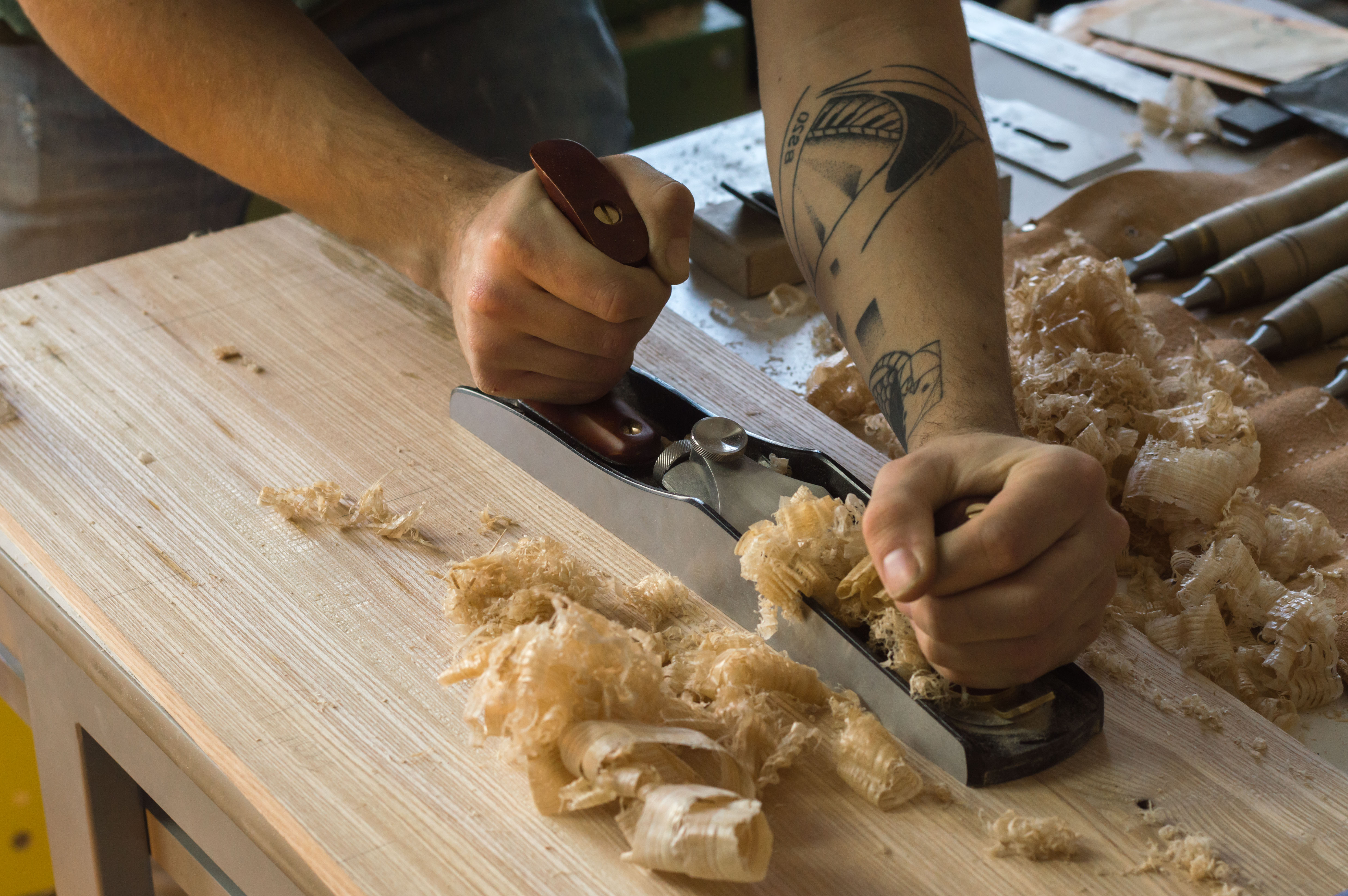
A plane is much more versatile than a scraper but does require more effort to sharpen, setup and use. A good all rounder is a No.5 jack plane. The jack of all trades. I use a low angle, bevel up plane which allows me to plane at three different angles for different purposes. Low angle for end grain and softwood. Normal for everyday use and high angle for tough or figured timbers; where it acts more like a scraper.
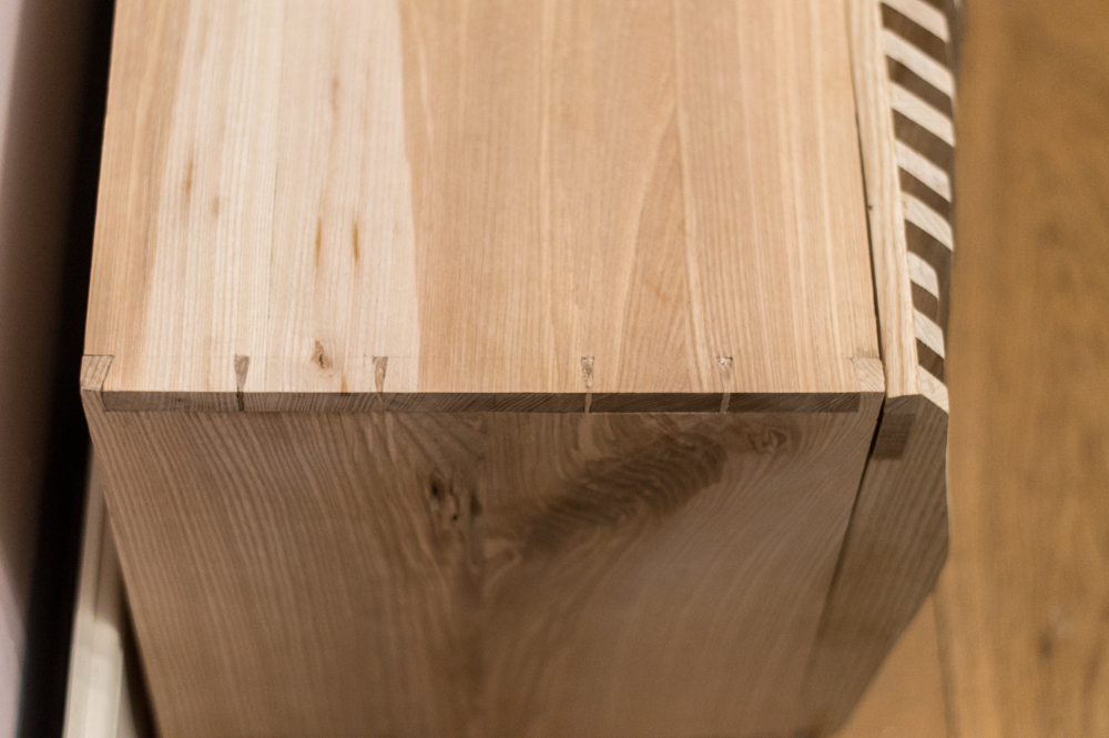
Dovetails Template
Here's a technical drawing for the dovetails. You're welcome to change them if you like but remember always to choose an odd number, it always looks better!
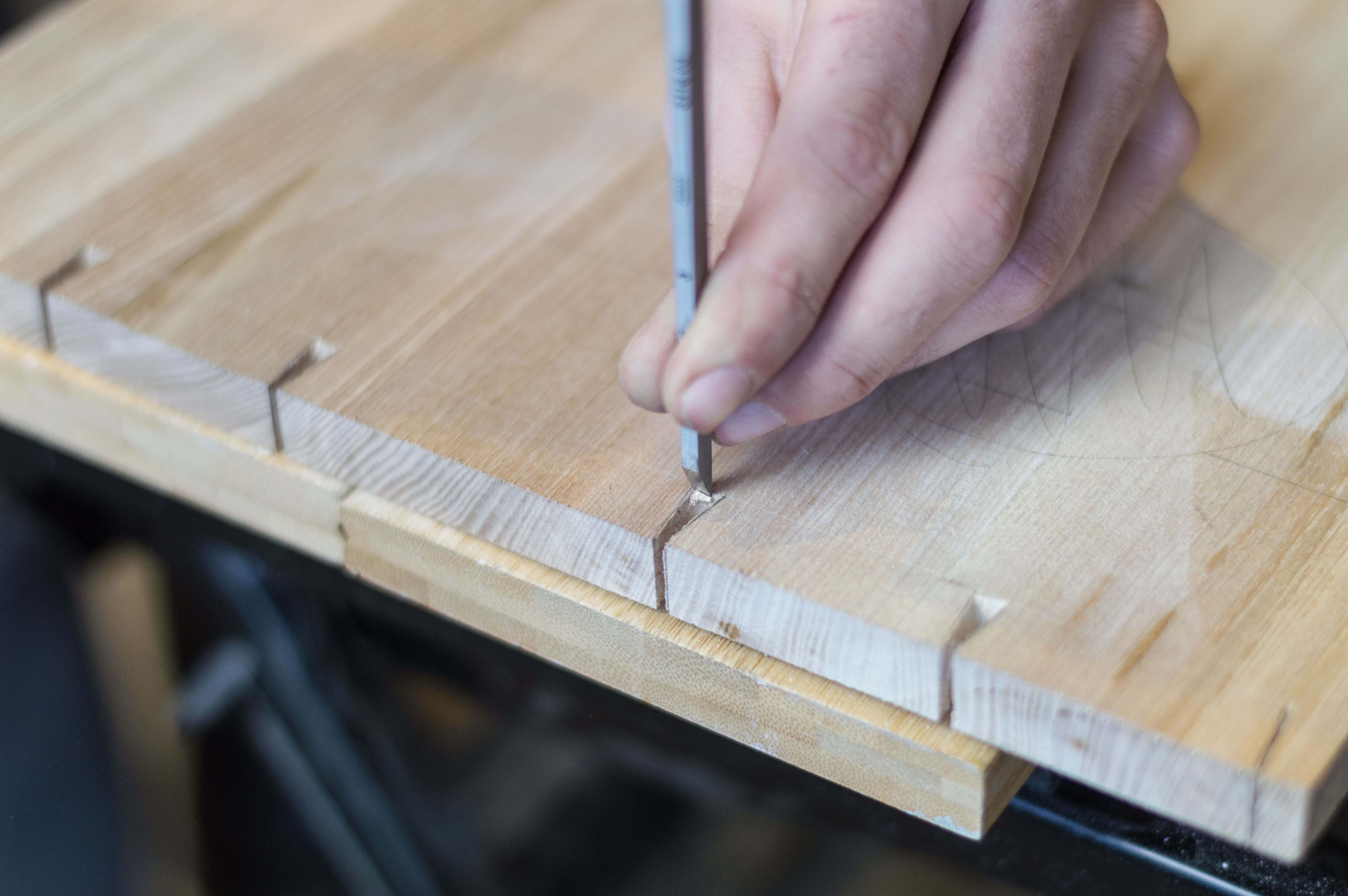
Marking Out the Tails
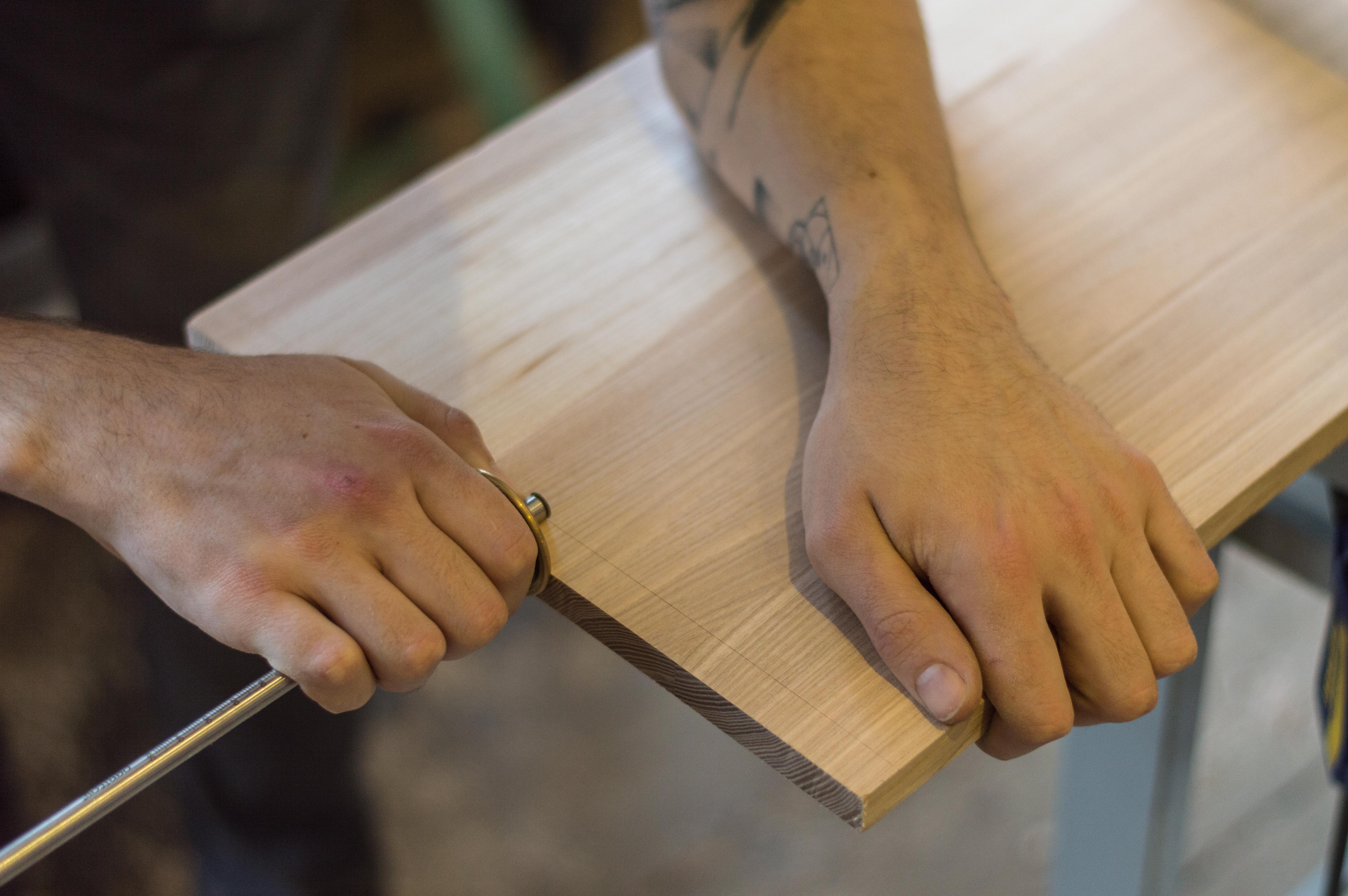

To mark out the tails I first set my marking gauge to 18mm and marked all sides of my four boards (top, base, side L side R).
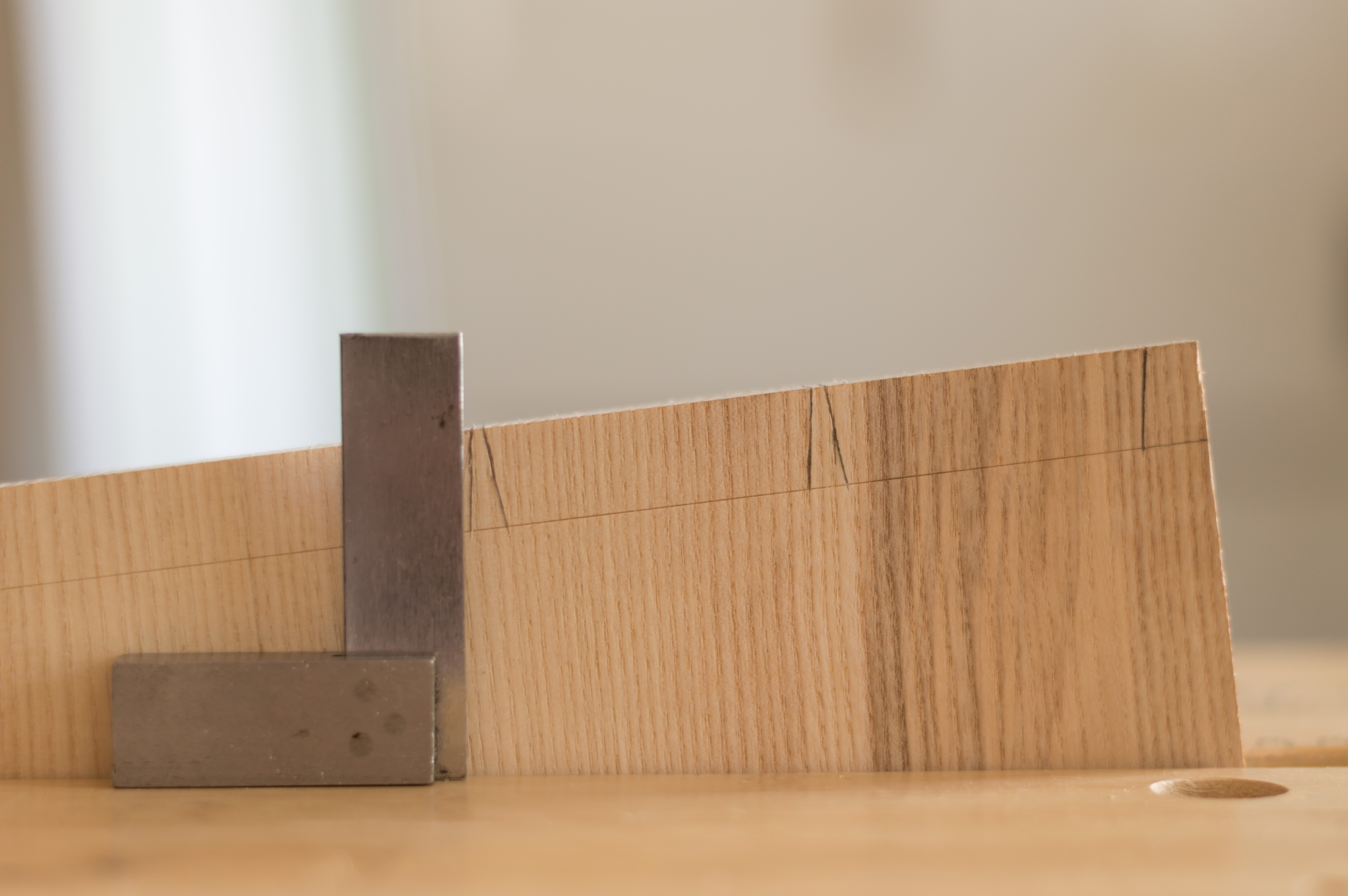
After I used my engineers square and ruler to mark out the top of the dovetails.
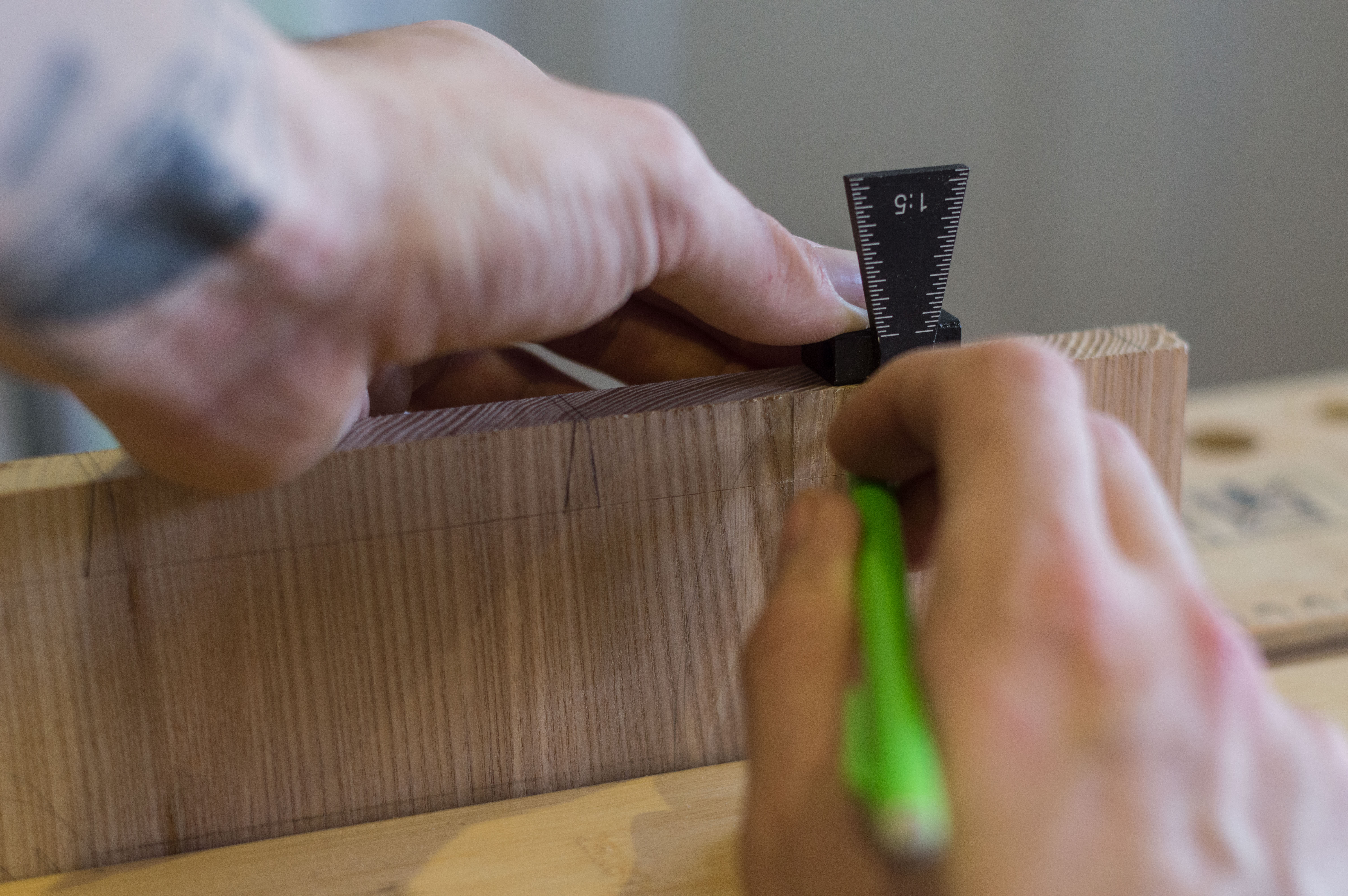
Next I use my dovetail marking gauge and a scalpel followed by a pencil at 1:8 which is suitable for hardwood.
Note: if you are using a softwood 1:6 would be better suited.
Cutting the Tails
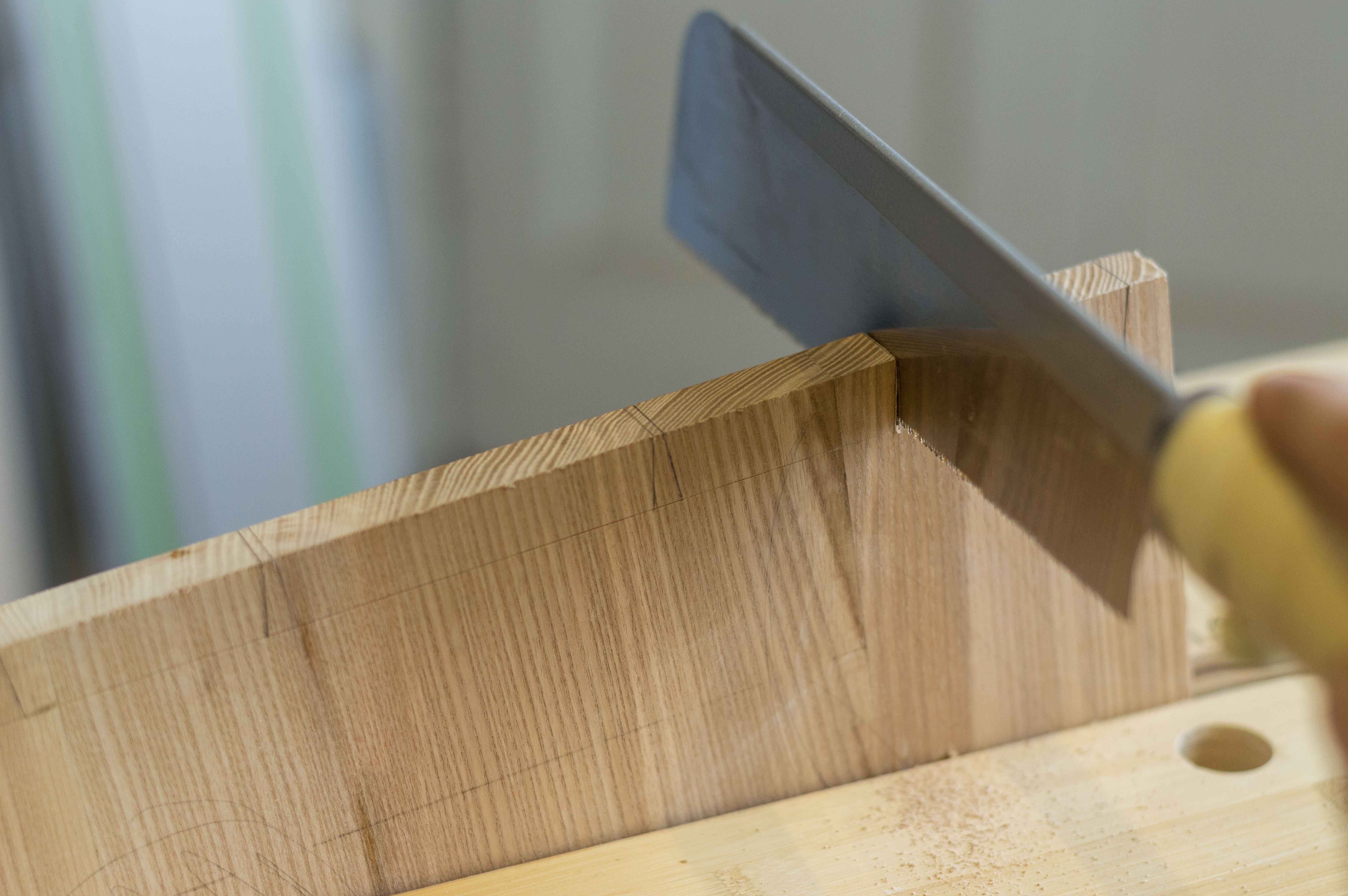
When cutting the tails I place both the base and top in the vice cutting them both together. I use my engineers square to align the cut parallel with my arm to make my life easier. Pro tip there.
I always saw with my cut line to the left and flip the piece when I cut again. This allows me to always be following the line with my eye as I cut.
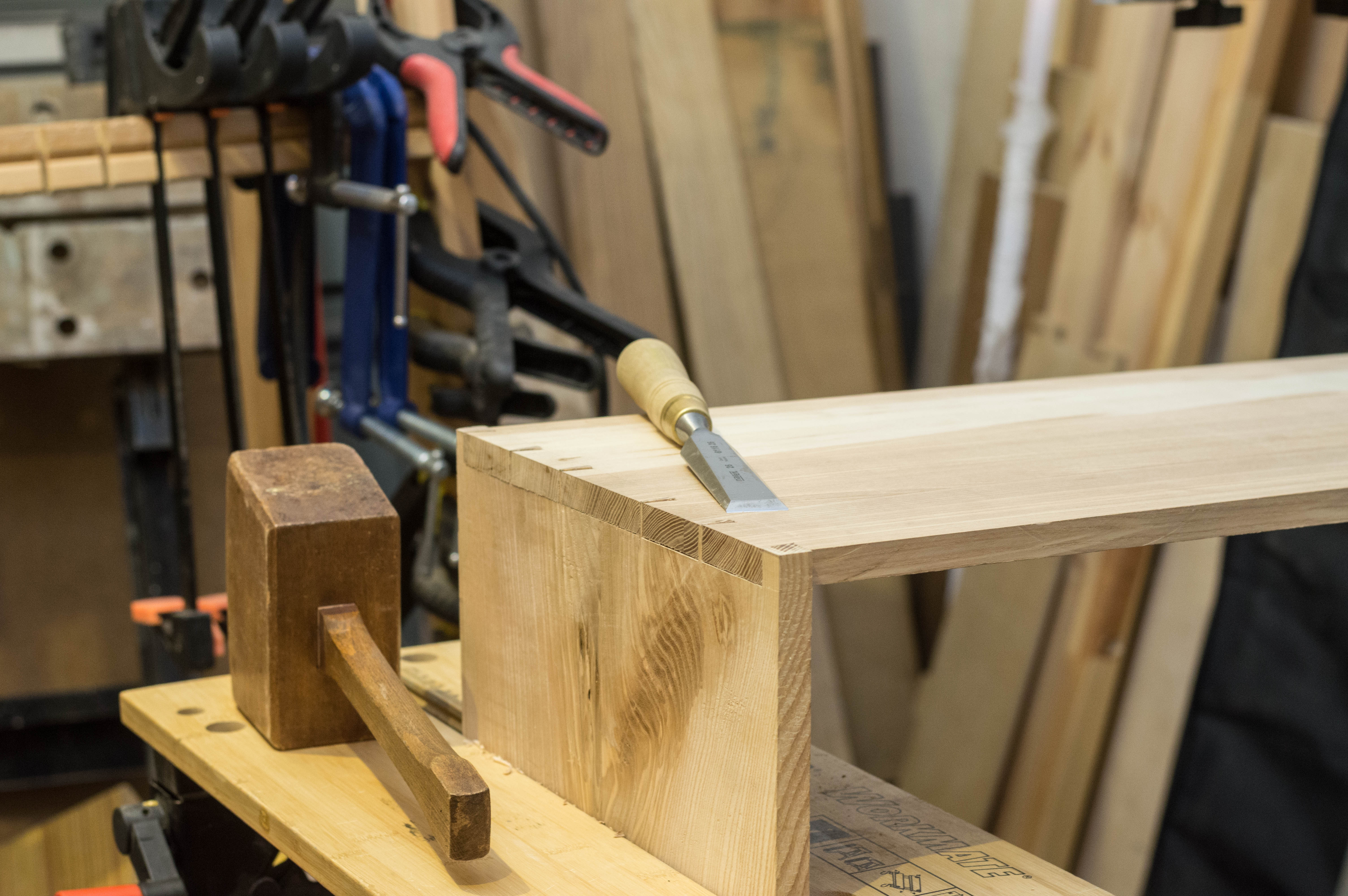
Removing Waste
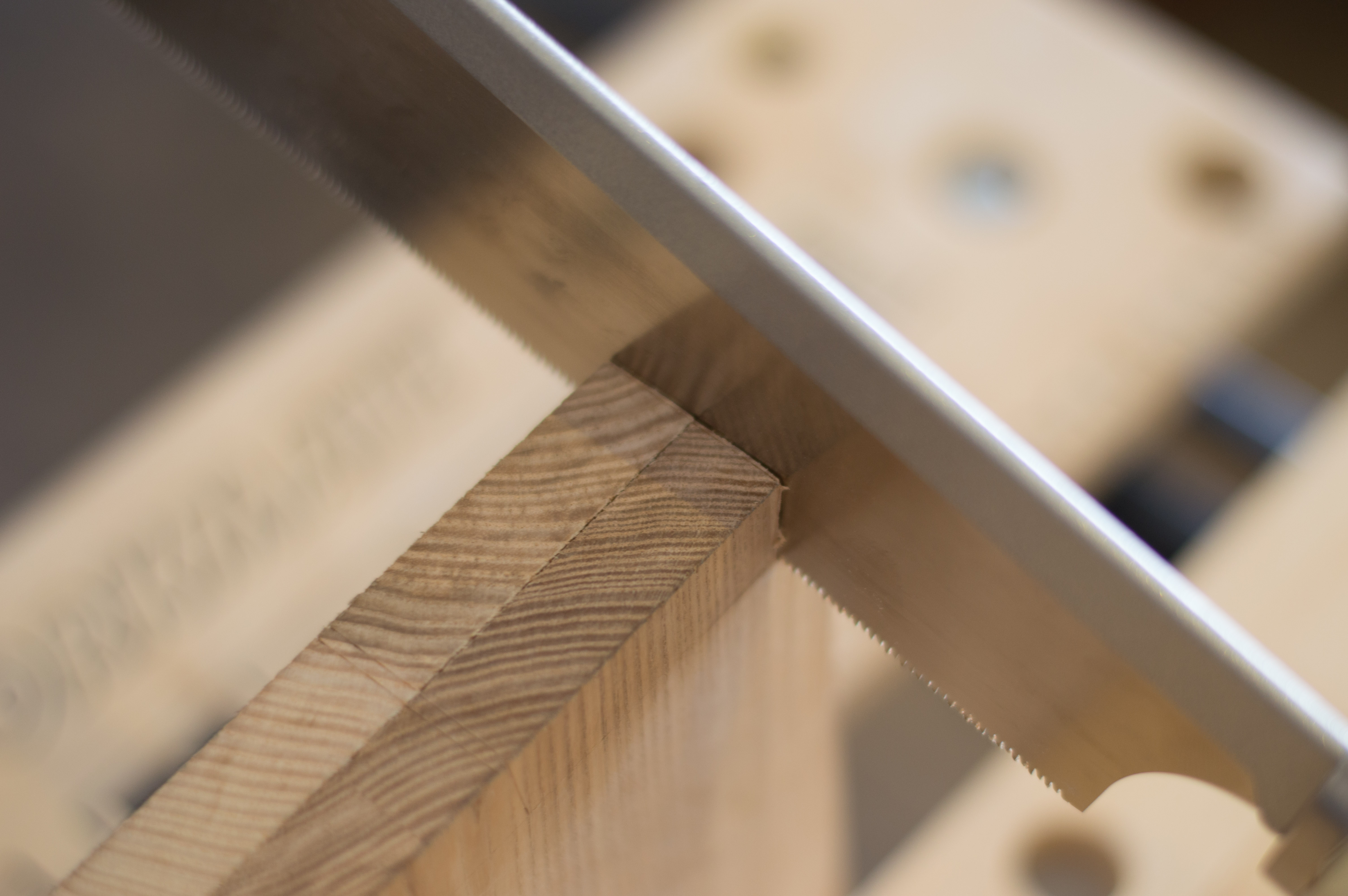
The first bit of waste I like to remove is the ends of the board as shown in the first picture.
After I use my jewellers piecing saw to remove the rest of the waste between the tails. I use a piercing saw instead of a coping saw for the smaller tails as the blades are much finer.
I then trim to my waste line using my 3mm chisel.
Note: when I chisel I only go half way through on each side this keeps the tails nice and neat.
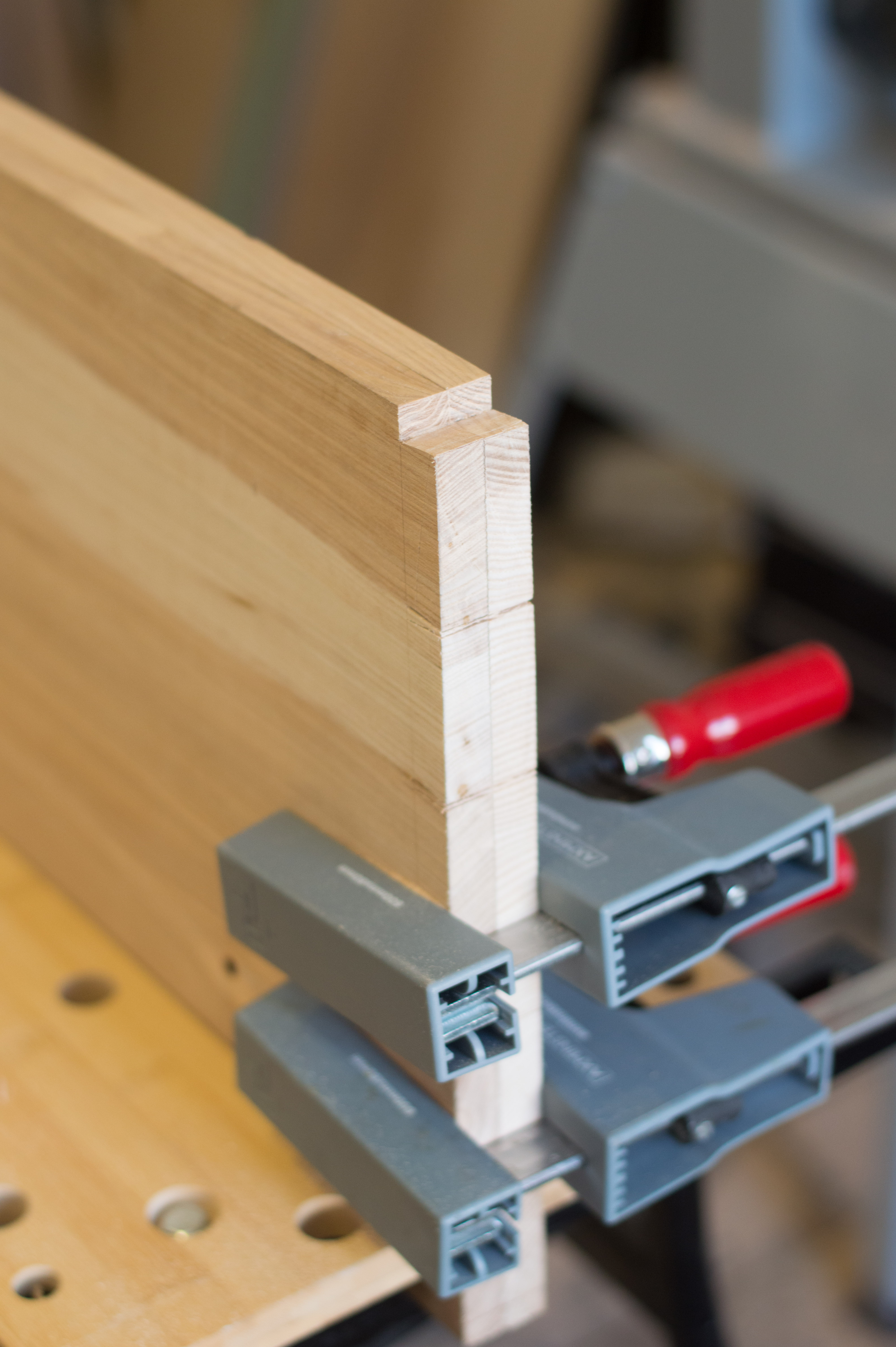
Marking Pins
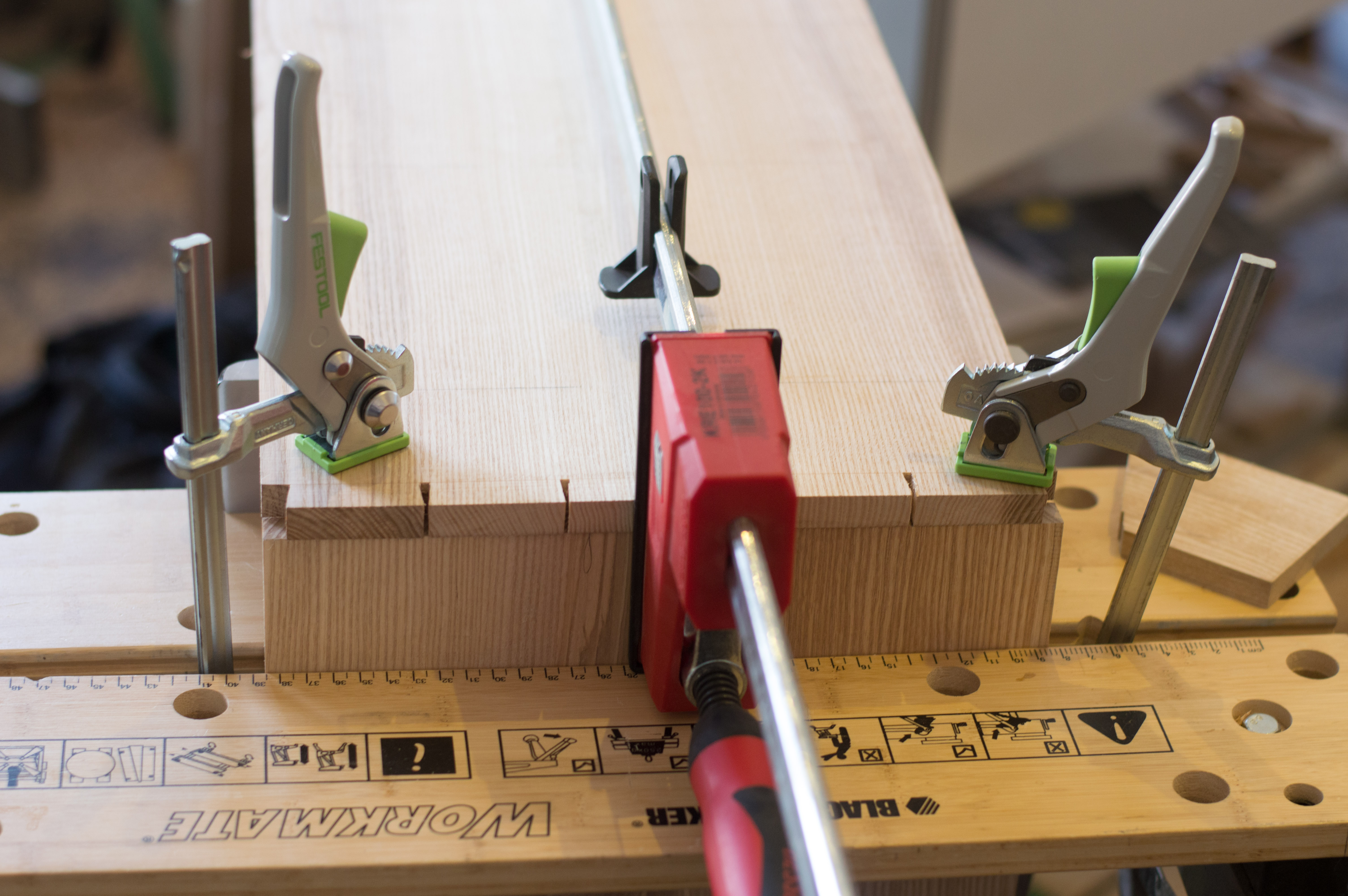
There are many different ways to mark out the pins. I like to use a scalpel and a plane on it's side supporting the referenced board and a few good clamps. What is important is that your boards do not MOVE!
Make cut lies only once using your scalpel/marking knife and do not trim the tails after this stage.
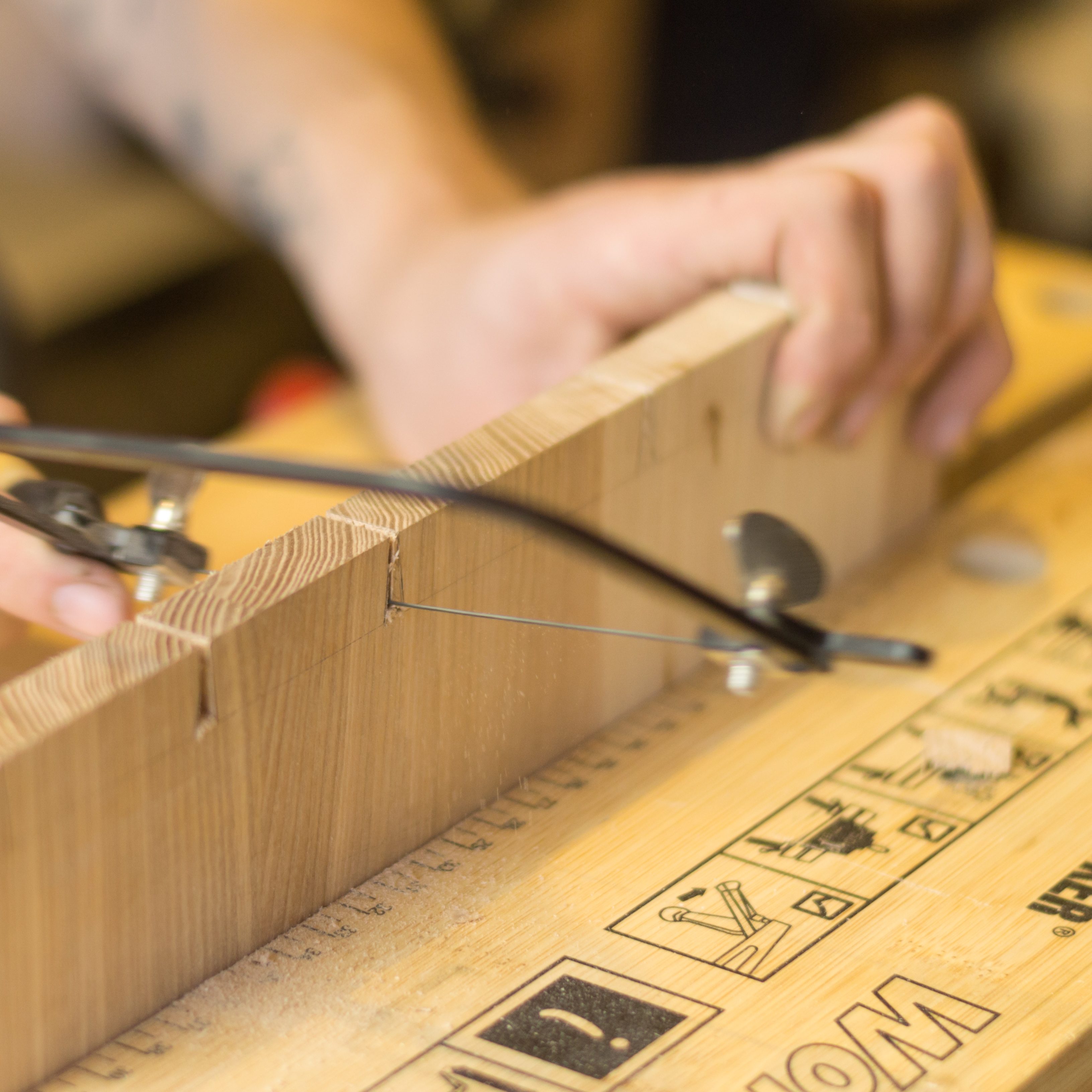
Big Waste Tiny Pins
So first use your dovetail saw to cut down to your line created by your marking gauge. Then back in with the piercing saw followed by chiselling to your waste line.
Note: depending on how much waste you remove with the piercing saw you may need to take a few passes before going to the waste line. Again only chisel halfway through on each side.
Oh So Crafty!
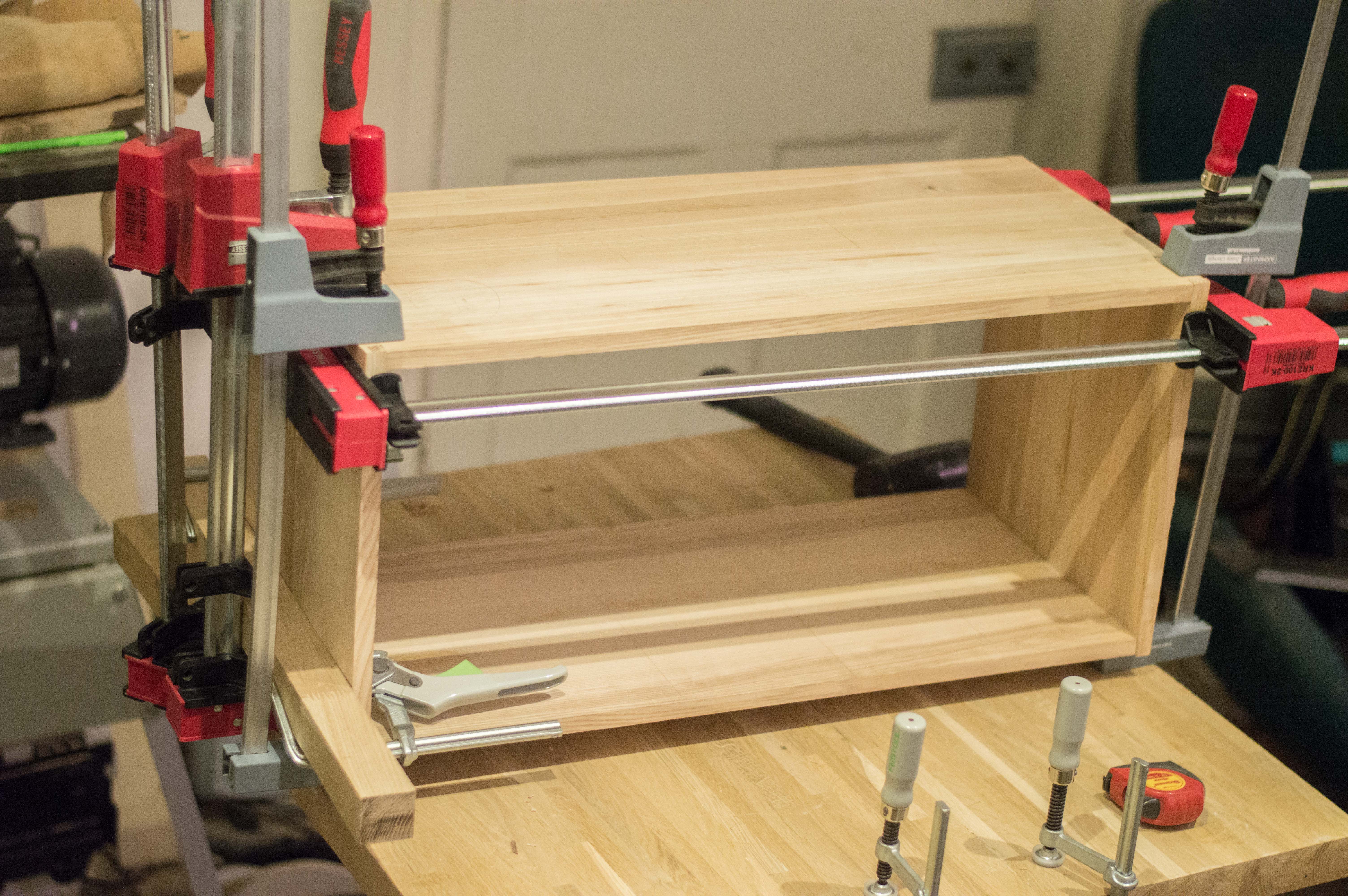
So when your test fitting remember to never remove material from the tail only the pins and listen to the wood. When it sounds hollow it has not seated properly, when you hear a deep thud leave it alone. Finally clamp the carcass together without glue slowly.
Note: Do not leave the pieces assembled overnight they can become very difficult to separate.
For the next section we will be moving on to the mechanism.
If You Buy a Cheap Mechanism You May Have to Modify It
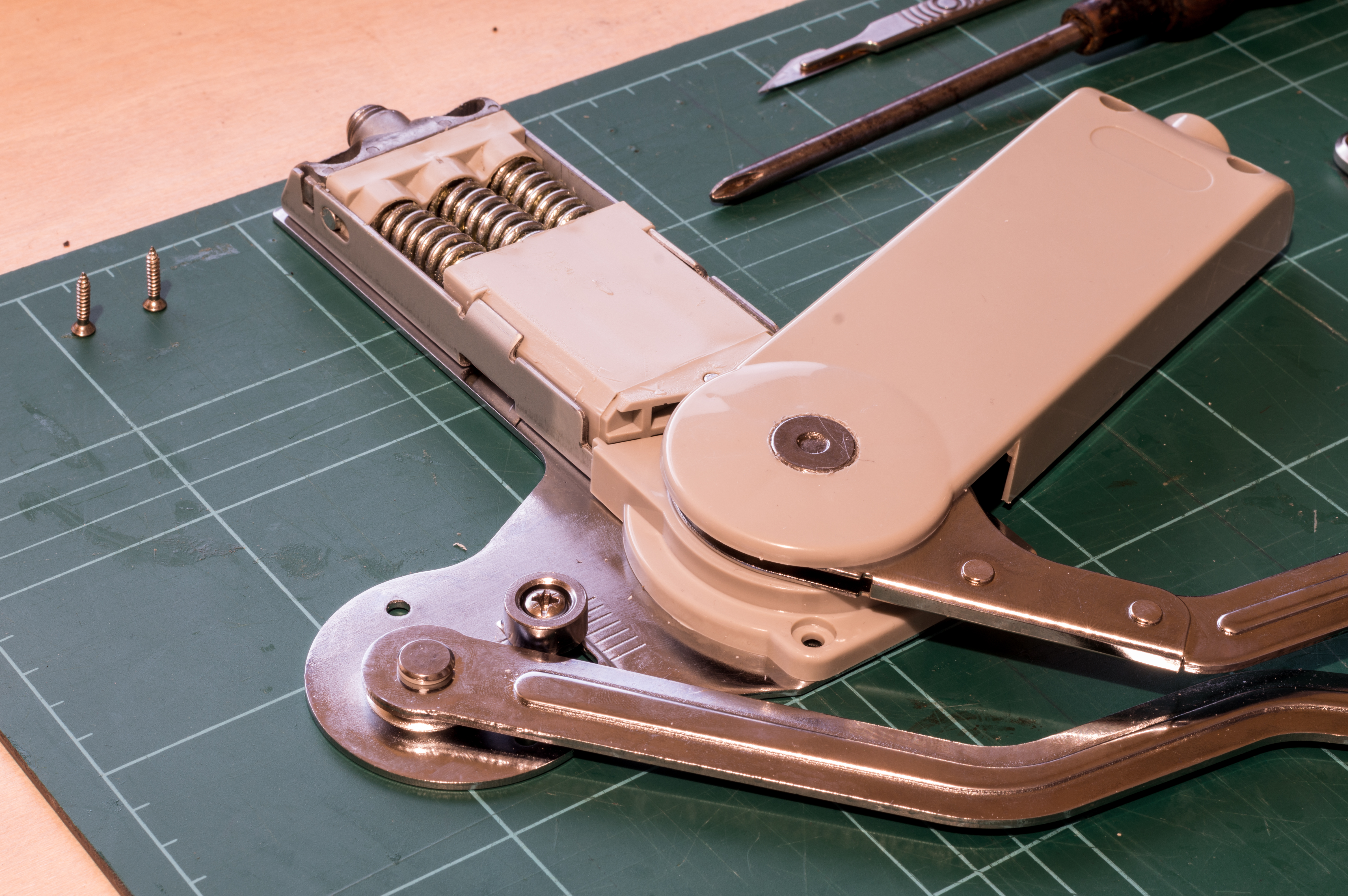
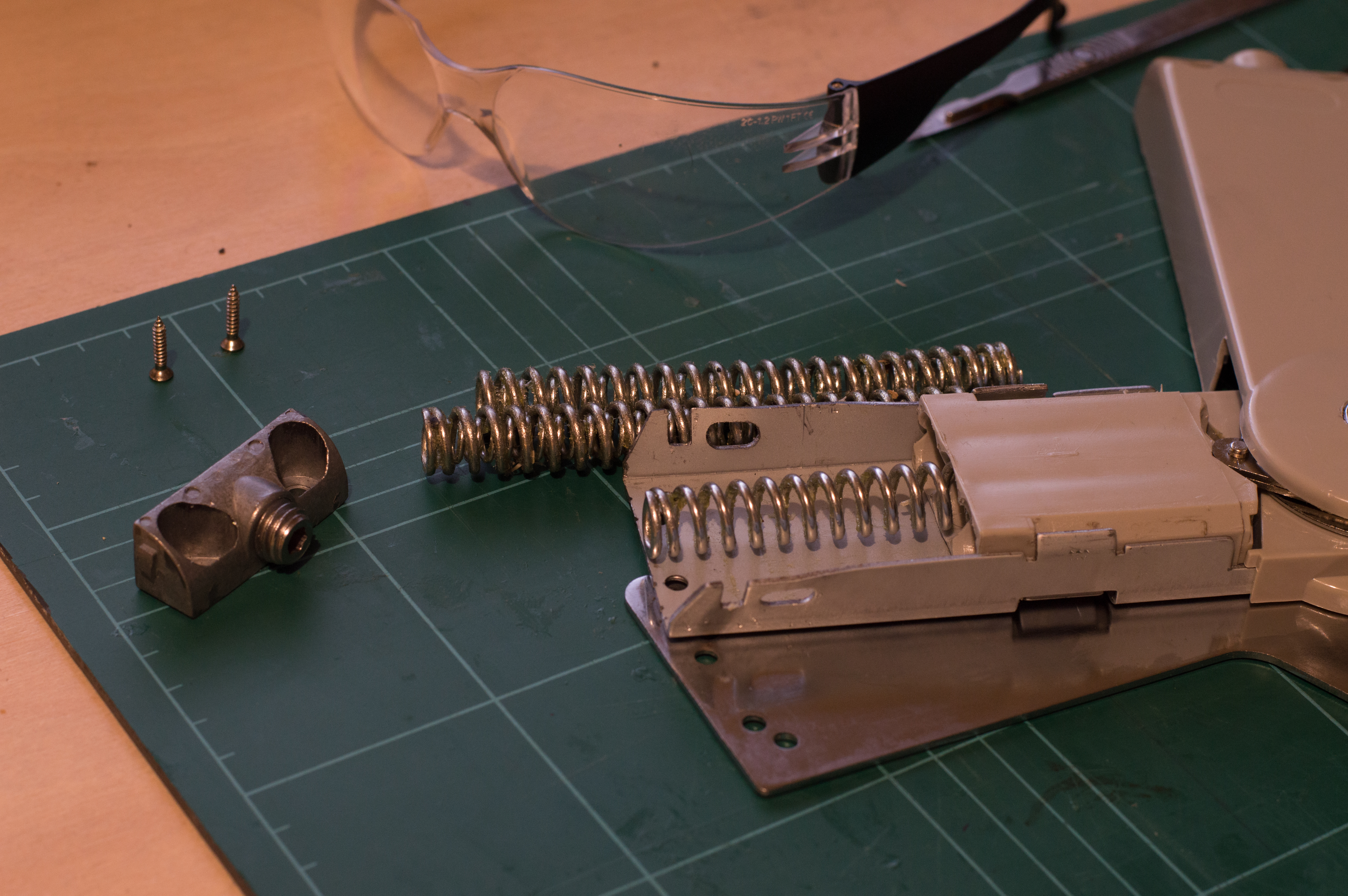
This is the first on I bought cheap on ebay, the pre-load was far to high so I had to modify it extensively to reduce the pre-load but it was still not quite right.
So This Is Actually the Second Mechanism I Bought
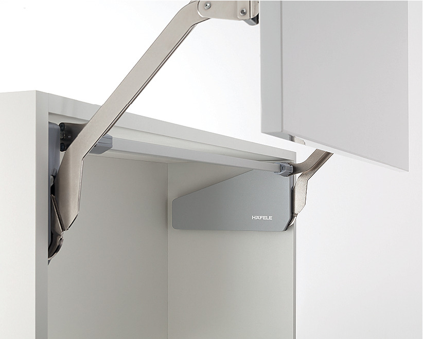

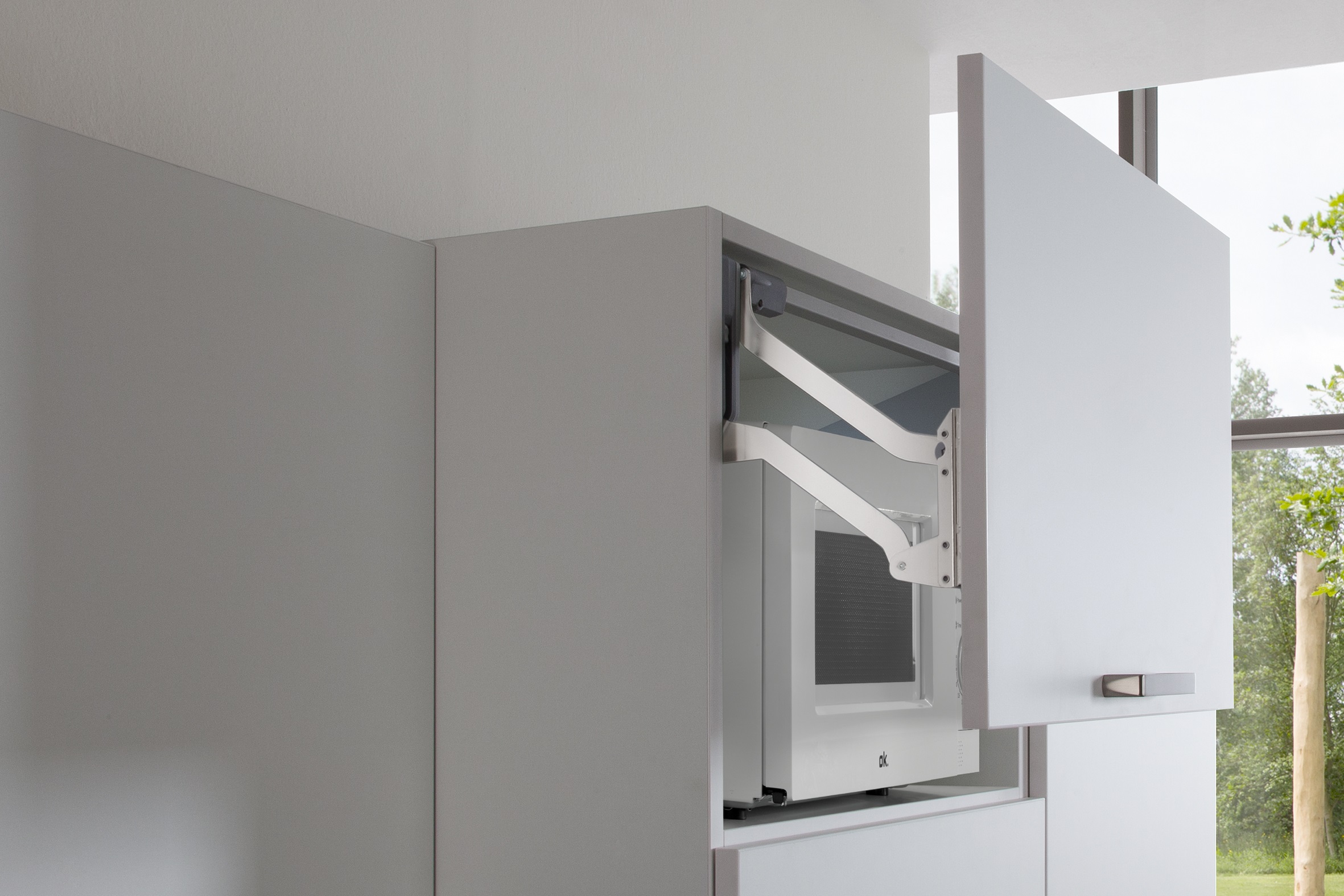
So this is the mechanism I ended up using. It's made by a company called hafele 372.33.500 - Free Up parallel lift up front fitting.
https://www.locksonline.com/Free-Up-parallel-lift-up-front-fitting-45006.html?gclid=Cj0KCQjw5-TXBRCHARIsANLixNwIsephtDbOFa9ERSo5tvC6RHg7r7veoGRn5KxsA9CA9P5rfKTDwdkaAqsiEALw_wcB
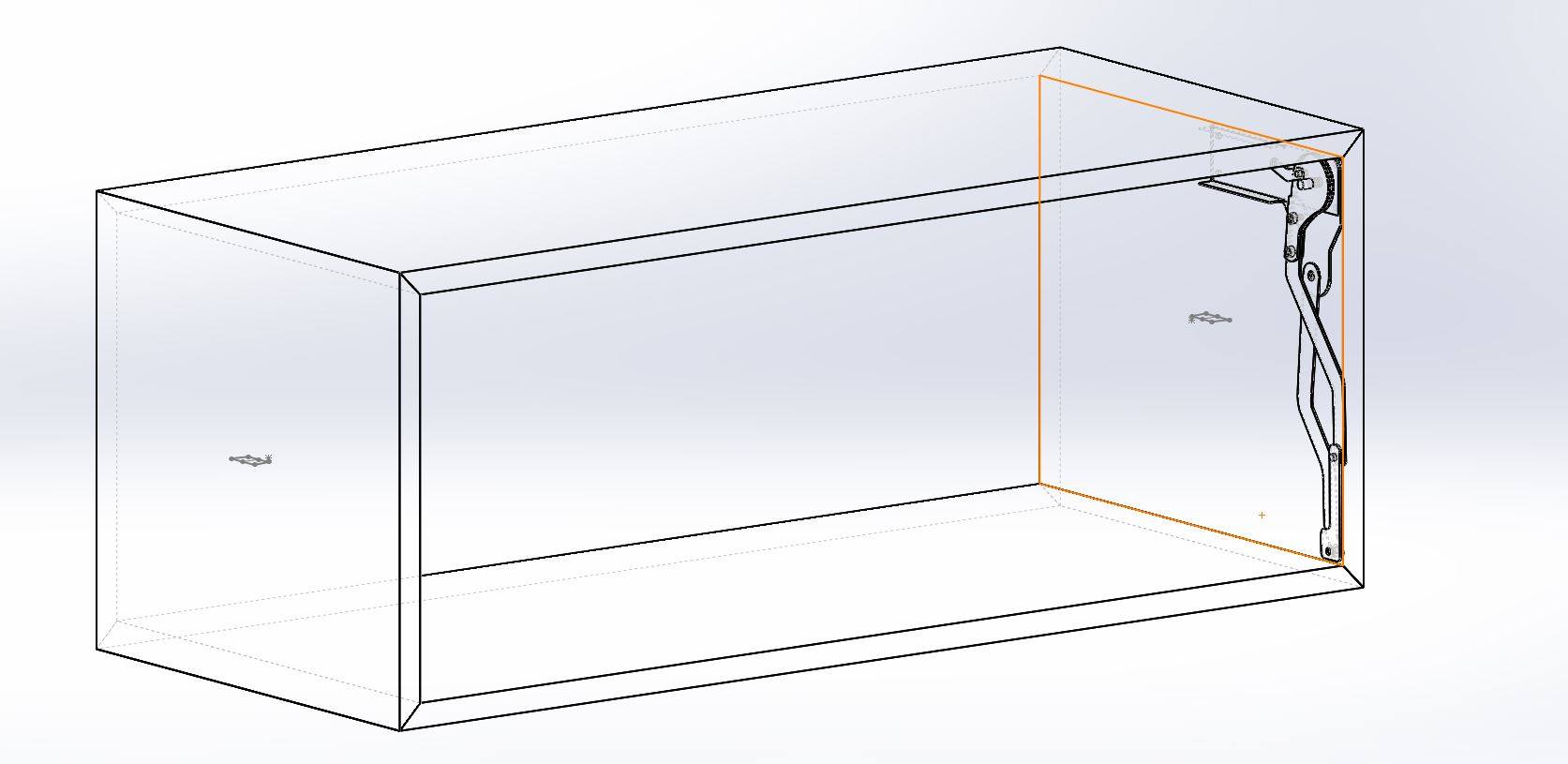
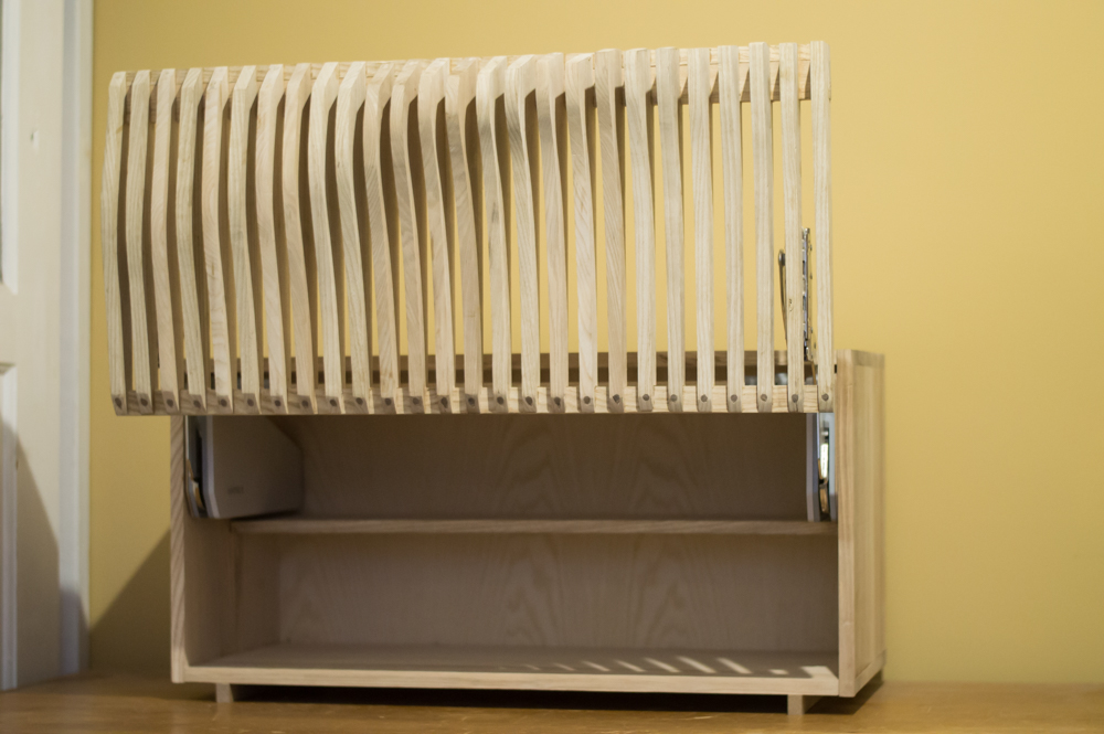
Mounting Mechanism
![image1[1805].jpeg](/proxy/?url=https://content.instructables.com/F2U/MBB8/JH6JCGCT/F2UMBB8JH6JCGCT.jpg&filename=image1[1805].jpeg)
![IMG_3752[1806].JPG](/proxy/?url=https://content.instructables.com/FIU/KMOE/JH6JCGDA/FIUKMOEJH6JCGDA.jpg&filename=IMG_3752[1806].JPG)
So when you buy a parallel lift you get given a paper template for marking out the positions of the screws. I find it incredibly useful to make a template from this for precise mounting. Mine is made from 3mm hardboard and worked just fine.
You Could Always Make Your Own Mechanism Though
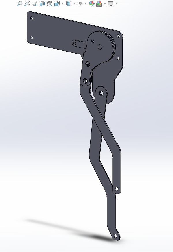
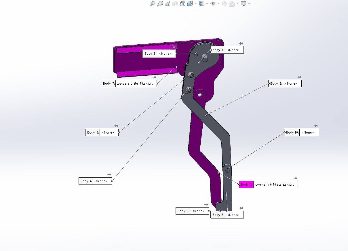
If you're feeling up to it I actually designed my own mechanism to this cabinet but never had the time to make it. If you would like the CAD files of the mechanism just send me a message.
Spacing
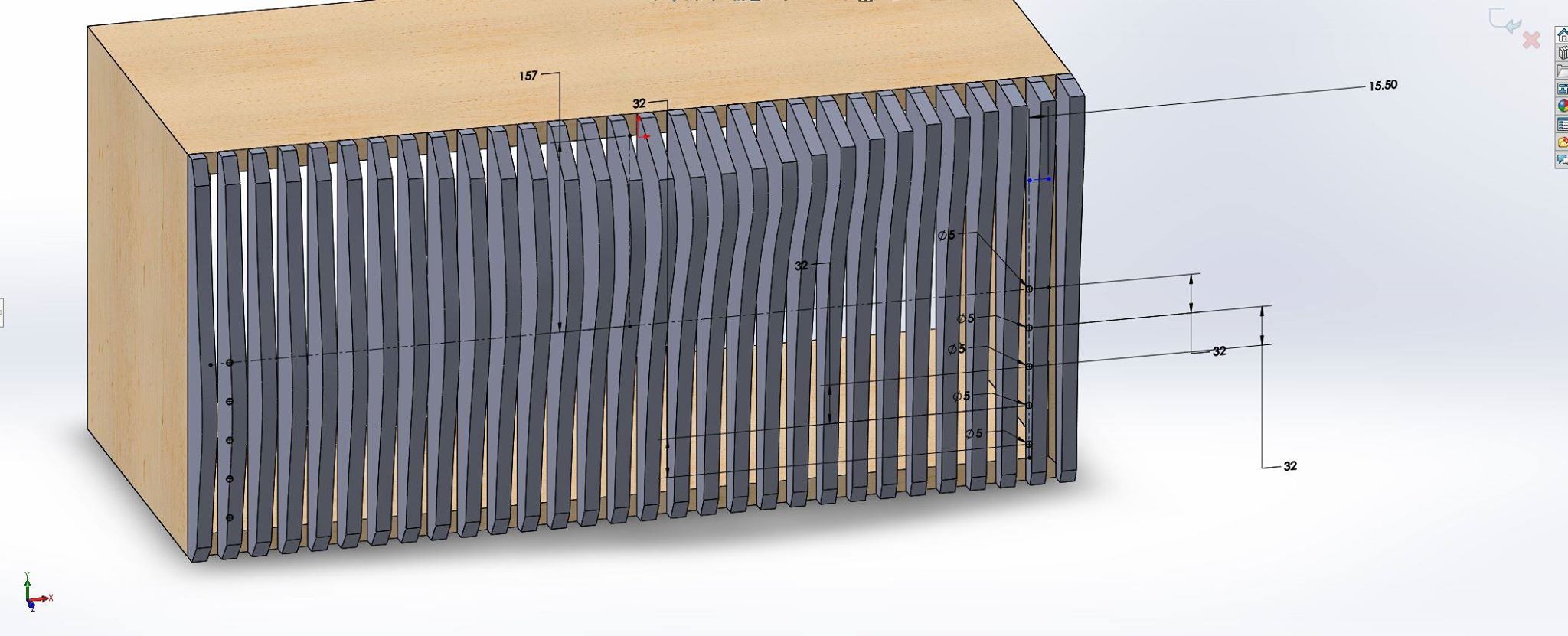
One important thing no matter what mechanism you use you need to check the spacing for the mount requirements.
If you use my spacing it will be perfect for the hafele system.
the spacing I use is 15mm between the slats.
Assembling the Front
![IMG_3765[1786].JPG](/proxy/?url=https://content.instructables.com/F4C/9500/JH6JCH30/F4C9500JH6JCH30.jpg&filename=IMG_3765[1786].JPG)
So I machined a fair amount of 15mm spacers to make assembling the front easier. I secured the pieces to the lower rail using walnut dowels. I ended up using 6mm dowels because they were left over form a previous project. This was a mistake as they caused the slats to split.
If you make this project i recommend 3mm dowels instead.
For the top section I used glue alone as the rail is much larger.
All Finished
All that's left now is to apply a finish, for this recommend a nice simple oil finish. My favourite product for this is called tru-oil, which is applied using a lint free cotton rag. I feel that finishing really comes down to a personal preference so equally use whatever you like/feel comfortable with.
If you would like a bit more advice on finishing with tru-oil have a look and my breadbin/ tambour project at step number 10. (link)
If you made it this far well done, and if you feel like making your own feel free. I'd love to see it!