Parallax BoE-Bot Remote Control Powered by Afero
by afero in Circuits > Remote Control
1873 Views, 7 Favorites, 0 Comments
Parallax BoE-Bot Remote Control Powered by Afero

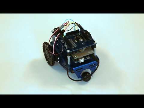
The Parallax BoE-Bot is a great platform for experimenting with robotics, and when I thought about adding an Afero Modulo to provide remote control it seemed like a natural pairing. The BoE-Bot's physical design would make it easy to add a Modulo, and Afero would give me a fast way to create a mobile app that would control the robot wirelessly.
Things You'll Need
First off, you need an assembled and working Parallax BoE-Bot, which is a great little Arduino robot kit that includes an Arduino Uno, two continuous-rotation servos, and a "Board of Education" shield. ("BoE-Bot" and "Board of Education" are registered trademarks of Parallax, Inc.)
You can find BoE-Bot kits in a variety of places, for example from amazon.com or your favorite electronics site.
Assemble the BoE-Bot kit per it's instructions. Then we'll make it better!
Parts needed:
· Afero Modulo from mouser.com
· Afero Plinto (includes two 18-pin male headers that we'll use) from mouser.com
· 1/2" long spacers for 4-40 bolts (4 needed) like these from mouser.com
· 3/4" long 4-40 screws (4 needed) like these from mouser.com
· 2" lengths of breadboarding wire (6 needed. I suggest you use 2 red, 2 black, and 1 each blue and yellow.)
Other stuff you'll need:
1. You'll need the Arduino IDE. Get it from https://www.arduino.cc/en/Main/Software
2. You'll need to download the Afero software. It's all free - go to https://developer.afero.io/get-started for links to the Afero mobile app (for iOS or Android) and the Afero Profile Editor (from the Chrome App Store). You'll find instructions to:
a) Install the Profile Editor into the Chrome browser on your computer
b) Install the Afero app on your mobile device
c) Create an account on the Afero Cloud (through the mobile app)
3. You'll need to get the Afero library that communicates between your Modulo and Arduino. This is available (free!) from github:
a) Download the zip archive from https://github.com/aferodeveloper/afLib
b) Unzip the archive (resulting in a directory called “afLib-master”)
c) Rename the folder from "afLib-master" to just "afLib"
c) Move the “afLib” directory (and all of it's contents) into your Arduino/libraries directory
d) Restart Arduino IDE
Temporarily Remove the BoE and Arduino From the Boe-Bot
1) Detach the battery-pack plug from the Arduino.
2) Detach the two servo connectors from the Board of Education. (When you assembled the BoE-Bot, the instructions advised you to mark the left and right servo connectors...if you don't have them marked, I suggest you mark them now. We will use the same convention as the original BoE-Bot instructions: the RIGHT servo will be the one on the right if you are looking at the underside of the chassis, with the tail wheel up at 12 o'clock, and the wheels down at the bottom).
3) Undo the screws holding the Board of Education to the four standoffs on the chassis, and remove the BoE shield and Arduino assembly.
4) Separate the BoE shield and the Arduino, and set them aside for now.
Attach the Afero Modulo to the Plinto Shield
The Plinto shield comes with a pair of header sets for your Modulo. If you look closely, you'll see these headers use round pins, not the square pins you often use with breadboards. The round pins fit the sockets on the Plinto--square pins won't fit. Make sure you use the headers supplied!)
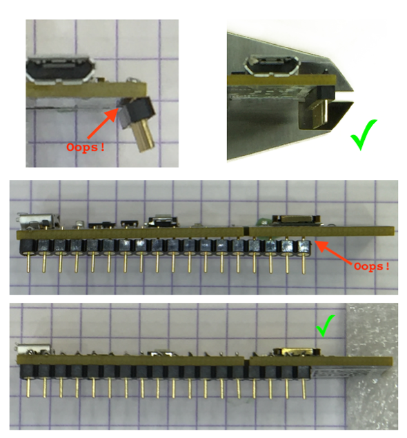
1) To attach the headers to Modulo, insert the short pins of a header through the underside of the Modulo (as shown in the photos). Make sure the pins are at right angles to the Modulo board, and then solder just the two end pins to the Modulo. Stop before you go farther!
2) With just the two end pins of a header soldered to the Modulo, inspect your work. You want to make sure that the header is flat along the Modulo, and the pins are at 90 degrees to the Modulo. If things look good, move on to the next step. If not, reheat the solder joints and correct--it's easier to do this now, with just two pins soldered, than if you had done them all!
3) Once you've got the header properly soldered in place by just the two end pins, go ahead and solder the other pins. This should be a fairly easy job, since the header is held in alignment for you. As always, keep your iron clean, and if you think the Modulo is getting too much heat, take a break and let it cool down.
4) Repeat with the other header.
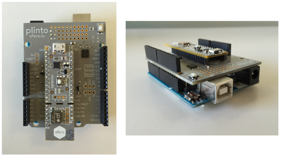
5) Once you've got both headers attached to the Modulo, you can attach the Modulo to the Plinto Shield. Plug the header pins into the sockets on the Plinto in the orientation shown in the photo, with the Modulo's USB connector up near the "Plinto" label and the bottom part with the Afero logo sticking out a little bit from the bottom.
Reattach the Electronics to the Boe-Bot Chassis
1) Plug the Plinto shield (with Modulo attached) onto the Arduino, as you would with any other shield.
2) Now plug the Board of Education shield on top of the Plinto. You will notice that Plinto (like Arduino) has more sockets than BoE has pins, so be sure you get orientation and placement correct: the Arduino USB connector should be opposite the breadboard end of the BoE, and the all pins in the 6-pin "Analog Pin" header should be inserted into the corresponding pins in the Arduino--same with the 8-pin header on the other side of the board (Digital pins 0-7). If you match up those two headers, everything else will be correct.
3) Now you should have a Modulo sandwich: Arduino on the bottom, Plinto/Modulo in the middle, and Board of Education on top.
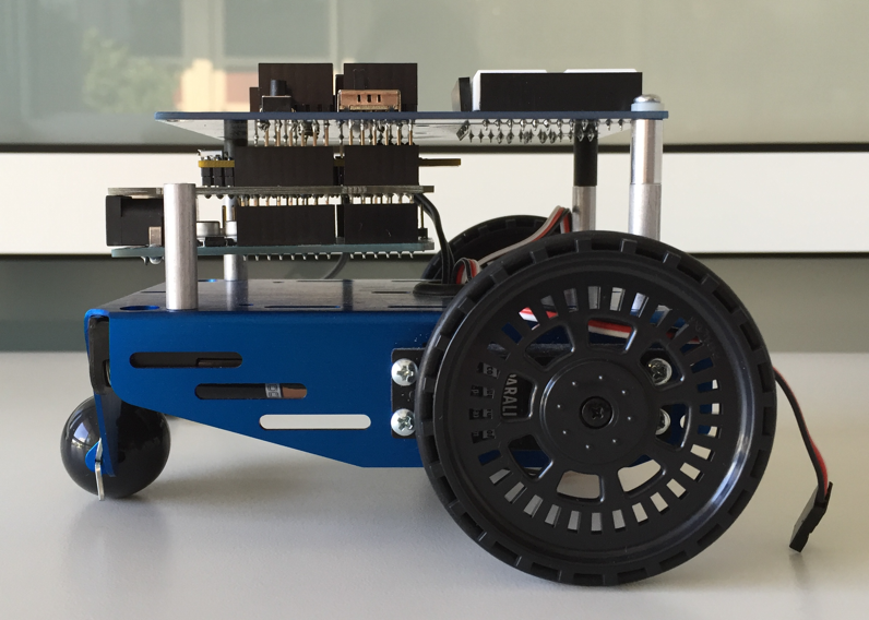
4) Reattach the Board of Education to the standoffs on the BoE-Bot chassis, but insert the 1/2" spacers to lift the BoE up to make room for the Plinto and Arduino underneath it. Use the 3/4" 4-40 screws to secure the assemblies together.
Wire the Servo Connectors
We'll be using digital pins 3 and 4 to drive the servos; these are not the same pins that the BoE-Bot uses by default, and we won't be using the BoE's servo sockets. Instead, we'll use short lengths of wire to run power, ground, and signal to the servo connectors.
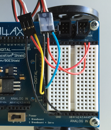
1) Run a 2" red wire from the center (red-wire) socket on each servo connector cable to "5V" header sockets at the top end of the BoE's breadboard
2) Run a 2" black wire from the black-wire socket on each servo connector to "GND" header sockets at the bottom end of the BoE breadboard.
3) Run a 2" blue wire from digital pin 4 to the white-wire socket on the right servo connector.
4) Run a 2" yellow wire from digital pin 3 to the white-wire socket on the left servo connector.
5) When you're done, your wiring should look similar to the photo above.
6) At this point you should connect Arduino to your computer using USB-B cable; this connection will be required during Profile publishing and Arduino programming.
Set Up the Arduino Project
1) Afero provides the "afLib" library which supports SPI communication between the ASR-1 and Arduino. If you have not yet done so, download afLib from github, unzip if necessary and install it into your Arduino libraries.
2) Create a project directory inside your Arduino directory--I named mine afCar.
3) Download the sketch file "afCar.ino" from GitHub and place it in your afCar project directory
4) Create an empty directory named “profile” in the same directory, next to the afCar.ino file.
How Arduino and Afero Communicate With Each Other
Modulo and Arduino communicate using “Attributes” that you set in the Afero Profile Editior.
You'll need to define the pieces of data that will be used to control the robot--the Afero platform calls these "attributes." These Attributes are the data shared between the controller app, the Afero Cloud, the Modulo, and the Arduino.
Afero provides a tool—the Afero Profile Editor—that makes it easy to define the attributes that your robot will use. Because the Afero mobile app understands attributes, there is no programming required, just attribute definition—once you’ve done that, the mobile app provides wireless control of any project. This makes it really easy and fast to create projects and try new ideas.
You can probably think of plenty of ways to drive the robot; the scheme we'll use is like a car: we'll have a control for speed, one for steering, and one to select forward, reverse, or "park." For this, we'll define 5 attributes:
· Speed for right servo and left servo.
· Current steering setting.
· Current speed setting.
· Current "Transmission" setting.
Creating the Profile Editor Project
Enough introduction...let's create the attributes:
1) Launch the Afero Profile Editor.
2) Click the "+" hex to start a New Project
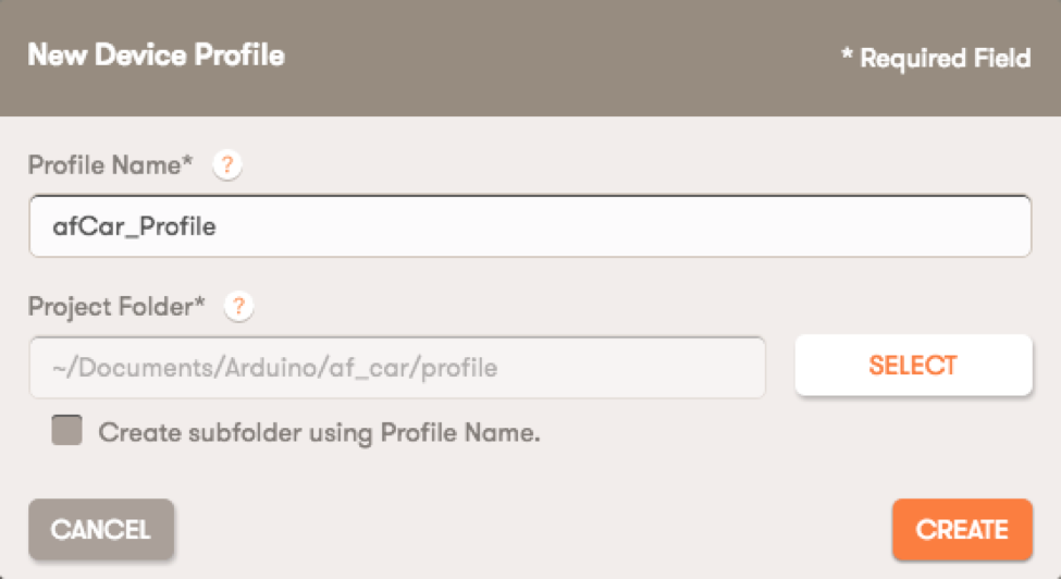
3) Name your profile (use "afCar_Profile")
4) Be sure "Create subfolder using Profile Name” is UNchecked (see above)
5) Click "Select" next to "Project Folder", navigate into the folder where you placed the afCar.ino file, and select the “profile” directory you created earlier.
This is a handy way to arrange your project code, because everything the Profile Editor creates will be stored in this "Profile" directory. Importantly, the Profile Editor will generate a header file ("device-description.h") used by the Arduino sketch, and this file layout supports that import without code changes.
6) Click "Create"
Defining a Device Type
The Profile Editor opens to the "Device Type" page. By default, we’ve already got a device type of “afCar,” which is fine, so we’ll leave that alone. You can add an optional Description, and you can select a Device Icon. You aren’t required to make any changes on this page at all, but go ahead and pick a cool icon! After you're done with any changes, "Save" in the upper right.
Defining Attributes
We’re at the heart of the matter: defining the data attributes which will carry control information for our robot. These steps are simple, but there are quite a few of them:
1) Click the “Attributes” tab in the left-hand nav.
2) Click "Enable MCU" at the top of the page. This sets up our project to work with an external microcontroller (in our case, the Arduino).
3) Attribute 1:
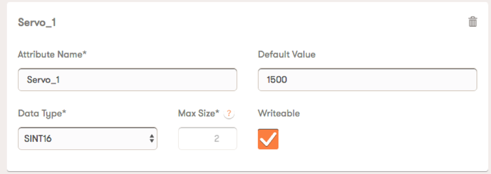
a. Fill in data for "Unnamed MCU Attribute 1"…change the name to "Servo1"
b. Set its "Default Value" to 1500
1500 is the neutral point for the servo we used: at this value, we expect the servo not to rotate. 1500 is probably the neutral point for the servos you have as well; if not, adjust this value accordingly.
c. From "Data Type," select "SINT16".
For each MCU attribute you define with the Profile Editor, you must define the data type that will hold any value the attribute might have. Since possible values for our servo will range from 1300 to 1700 a signed 16-bit integer works fine.
d. Check the "Writable" box, which makes this attribute read/write.
4) Now click the "+ New MCU Attribute" button to make room for Attribute 2.
a. Fill this one in exactly the same as the first, but name it "Servo2".
5) Click "+ New MCU Attribute" to define Attribute 3:
a. Name this one "Steer_Attr"
b. Give this one a default value of 0.
We will treat 0 as the center point of steering, and so we'll default to going straight.
c. Like the two previous attributes, select SINT16, and make this one Writeable.
6) Click "+ New MCU Attribute" to define Attribute 4:
a. Name this one "Accel_Attr"
b. Again, we'll use a default value of 0.
This attribute is our "Accelerator", and we're defaulting to "foot OFF the gas."
c. And again, select SINT16 and set the attribute Writeable.
7) Click "+ New MCU Attribute" one last time.
a. Name this last one "Transmission_Attr"
b. Default value 0, SINT16, and Writeable...just like the others.
(By the way, you may think, "The transmission only has 3 values: -1, 0, and 1. It doesn't need to be an SINT16!" Good for you! That's correct, of course. We could use a data type requiring fewer bits, but we arbitrarily decided to make all attributes the same data type. If memory was so tight that every byte was critical, we'd decide the other way.)
8) Click Save!
That's it for Attributes.
Create UI Controls
We use the "UI Controls" page to define controls that appear on the Afero mobile application. The controls let us to set the values of our attributes, and that’s how we control our robot. In the Profile Editor, we select control type that's suitable for each attribute and how we want to manipulate it. The Profile Editor provides several types of controls, some for discrete values, and some for ranges. For our robot, we'll use sliders to vary the steering and speed, and a "menu control" to select from the discrete values for the transmission.
Note that two of our attributes--the servo speeds—are not controlled directly from the UI. Our Arduino code will change these attributes when it sees that we have changed the values of the others: the steering, accelerator, or transmission, so we’ll need to create UI controls only for those last three attributes. You might think of this like a car with anti-lock brakes: the UI of the car includes just one brake control (the pedal), but the ABS computer uses the state of that pedal, along with other data, to decide exactly what to do with the brakes.
1) Click the “UI Controls” tab in the left-nav
2) Click "+ New Control". You will be offered a palette of types...select "Slider Control", and click "Add."
a. In the window that appears, from the "Attribute" selector, choose "Steer_Attr," to tell the editor this control is for the Steer_Attr created earlier.
b. For "Default Label," enter "Steering".
c. For "Min" enter -100; for "Max" enter 100; for "Step" enter 1.
d. Do not change "Control Type," "Unit Label," or "Primary Operation."
3) Click "+ New Control" again, and again choose "Slider Control", and "Add."
a. From the Attribute selector, choose "Accel_Attr."
b. For "Default Label," enter "Accelerator".
c. For "Min" enter 0; for "Max" enter 200; for "Step" enter 1
d. Do not change "Control Type," "Unit Label," or "Primary Operation."
4) Click "+ New Control" once more. This time select "Menu Control", and "Add."
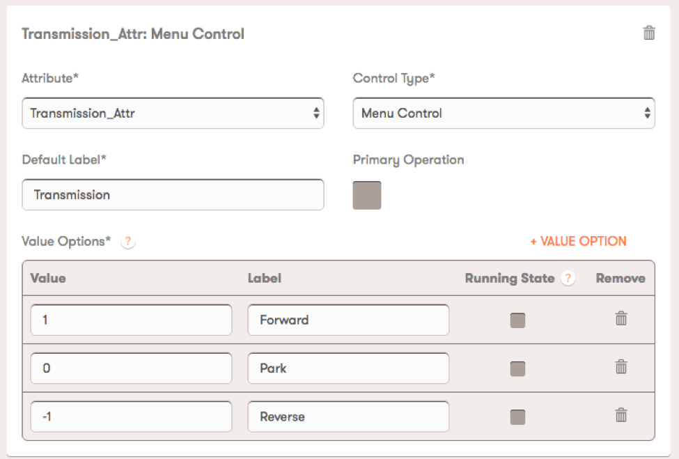
a. From the Attribute selector, choose "Transmission_Attr."
b. For "Default Label," enter "Transmission".
c. This time, we're going to need 3 "Value Options". Click "+ Value Option" twice, so that there are 3 rows in the Value Options area.
d. In the top Value Options row, enter 1 for Value, and "Forward" for "Label."
e. In the middle Value Options row, enter 0 for Value, and "Park" for "Label."
f. In the bottom Value Options row, enter -1 for Value, and "Reverse" for "Label."
g. Do not change "Control Type" or "Primary Operation."
5) Click Save in the upper right.
We're done defining UI Controls.
UI Control Groups
UI Control Groups are a way to organize controls. For our project, we don't need anything special: we're going to put all our UI Controls into a single group.
1) Click “UI Control groups” in the left-nav
2) Click in the dotted circle at the bottom of the pattern. A small panel opens up.
3) In that panel, for "Group Label" enter something like "Car."
4) To the right of that, click the "image" icon, choose your favorite icon, and click "Use this one!"
5) Then drag and drop "Steering" from the right into the dotted box labeled "Drop your controls here."
6) Do the same with "Accelerator" and "Transmission". From top to bottom, they should be arranged "Steering," "Accelerator," and "Transmission."
7) Click "Save" in the upper right of the screen
Publishing the Profile
When you Publish your new profile, the Afero service will:
· Generate the device-description.h file to be used by Arduino
· Transmit the attribute definitions you just created over the air, to be received by the ASR-1 chip on the Modulo and by your mobile device.
To do this:
1) Click "Publish" in the left-nav of the Profile Editor
2) Launch the Afero app on your iOS or Android device (and don't let the device sleep during the following steps.)
3) Make sure that the BoE-Bot is plugged into your USB cable (it should be at this point, just double-check).
4) After a minute or two, you should see your Modulo appear in the "Developer Devices" list in the Profile Editor.
(If the device does not appear, re-check the USB cable from your computer to the robot, re-check the Afero app on your mobile device, and confirm that the Arduino and Plinto are correctly connected together and connected to the Board of Education.
5) In the Profile Editor, click the checkbox to the left of your Developer Device. Then click the "Publish" button in the upper right.
The Profile Editor will show you progress, and should tell you when your Modulo has received the new profile...this takes a minute or two.
Once the profile has been published, you’re done with the Profile Editor.
As a shortcut, if you're having trouble with the Profile Editor steps, you can download the profile from GitHub and save it in the profile directory inside the Arduino project, but you'll learn a lot more if you do it yourself!
Program the Arduino
We're almost done!
1) At this point, you need to fire up the Arduino IDE, load afCar.ino, and upload that to the Arduino in your robot.
2) Watch the Serial Console output---you should see something like this:
Serial up; debugging on, script starting.
onAttrSetComplete() attrId: 1 value: 1500
Updating RIGHT servo with speed: 1500
onAttrSetComplete() attrId: 2 value: 1500
Updating LEFT servo speed: 1500
onAttrSetComplete() attrId: 65021 value: 257
Note: If your servos have a neutral point other than 1500, you should change the values on lines 15 & 16 in the afCar.ino file. You may also wish to change these values to fine tune your robot’s behavior, because individual servos may have an actual neutral point that’s a little different than the specification. The values on lines 15 & 16 should result in no wheel rotation when the robot’s in “Park” mode.
Drive!
Now that both the Modulo and Arduino are programmed, the robot should be ready to go.
1) Disconnect the USB cable.
2) You'll want to give it portable power, so plug in the battery pack to the Arduino.
3) On the Board of Education, move the power switch to position 1: Breadboard.
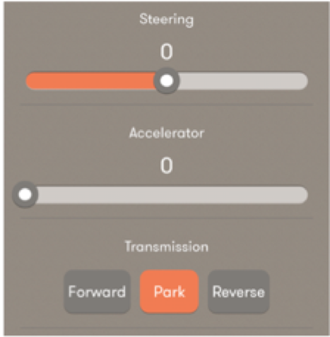
4) Launch the Afero app on your mobile device, and wait for the hex with your app icon to show that it’s active. Then tap that hex to launch robot control: you should see the UI that you defined--it will look something like the picture above, depending on your mobile device.
5) To start driving, use the Transmission buttons to "put it in gear," the Accelerator slider to give it gas, and the Steering slider to guide it.
[ If the robot doesn’t seem to listen to the Afero app, try pressing the “reset” button on the Board of Education, and waiting a few moments while the program resets, then try again.]
You've got remote control of your Arduino 'bot!
Finally, don’t forget that breadboard on top of the Boe-Bot—it’s just begging you to add sensors to your robot, and when you do, you can add them as attributes in your Profile as well, and get telemetry displayed on your mobile device!