Paper Circuit Simon Says
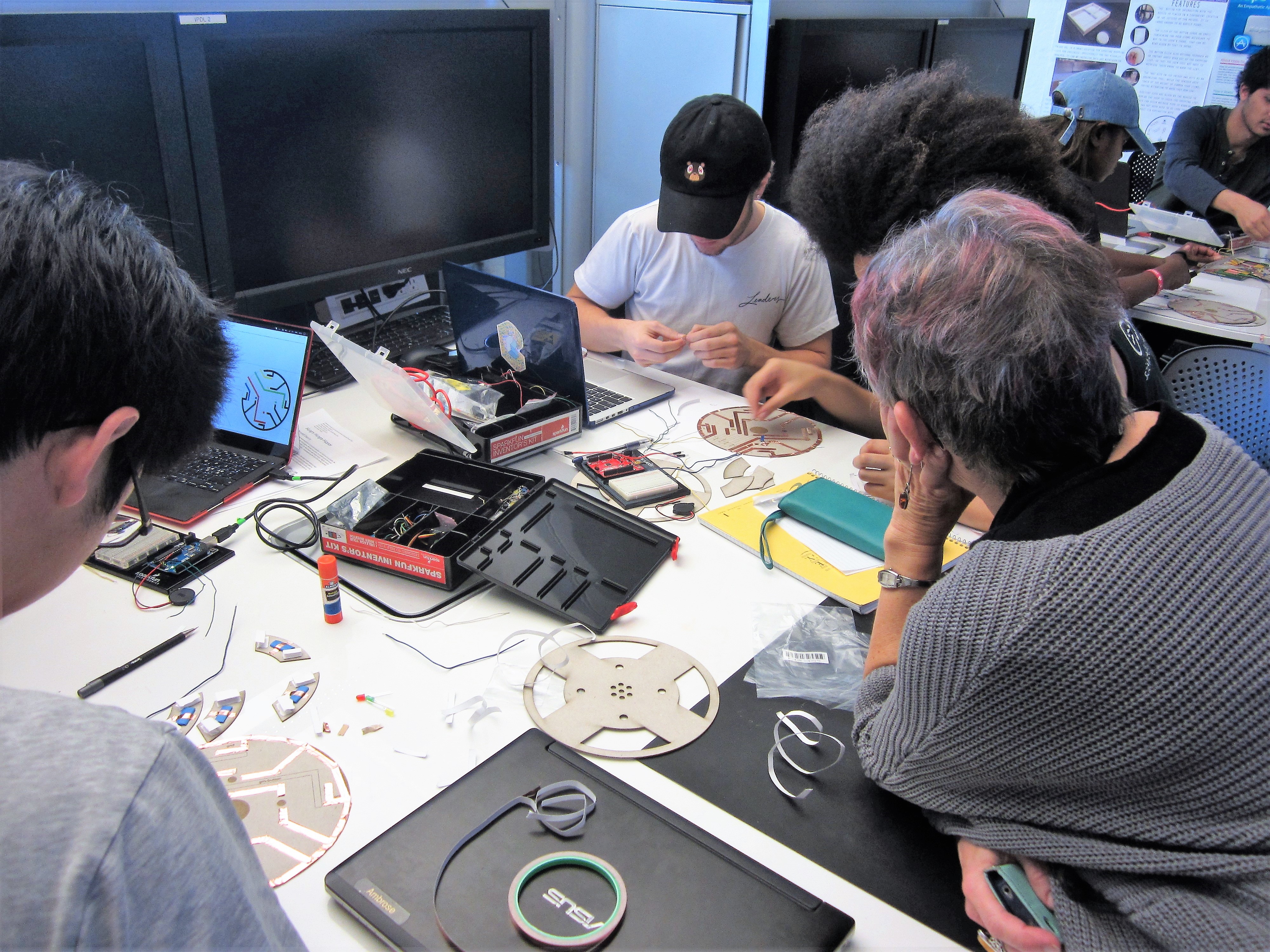
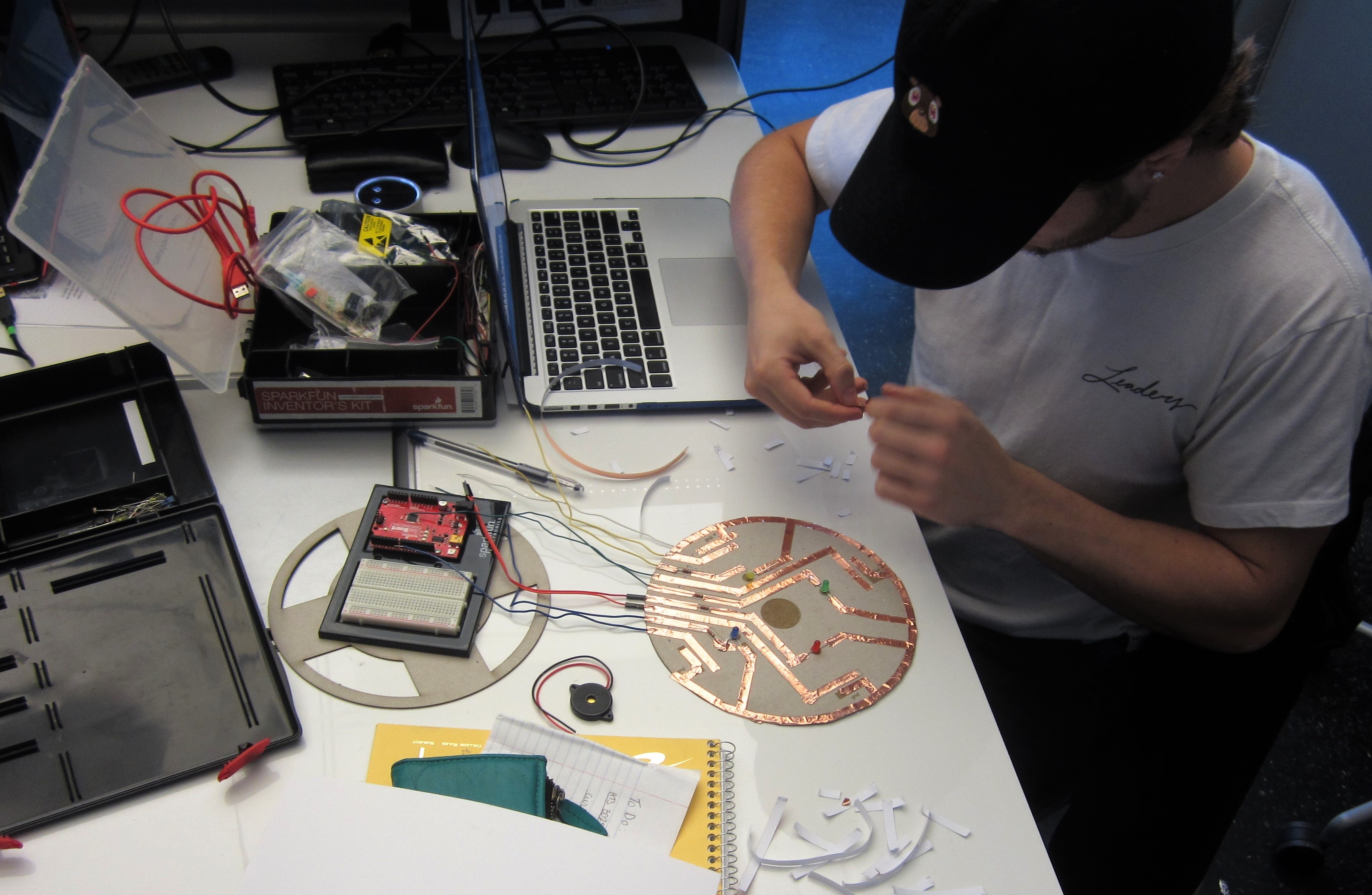
I TA'ed for a course called Experimental Games, where my students design and prototype playthings for really young children. My professor teaches the students about childhood development and mechanisms of play, but it was my job to introduce basic physical and electronic prototyping skills, so that the students could create more immersive and engaging projects throughout the semester.
This project was created as a lab activity for my 12 students, and it was well received. Each team of two managed to complete the project within an hour and a half. If you'd like to run this lab yourself, I've attached my .pdf instruction slides. It's a paper circuit translation of this guide by HelloTechie.
(As a heads up, most of the pictures of the step by step were taken when I was still developing the lab. The templates were smaller, and I didn't go in the same steps as I now advertise. Hope it isn't too confusing.)
Components per Kit:
- 4 330 Ohm resistors
- 4 LEDs (blue, red, yellow, green)
- Conductive tape (with conductive adhesive)
- 1x piezo speaker
- Arduino Uno (or Arduino-like microcontroller) and USB cable
- solid-core wire (or jumpers)
- 1 ply chipboard
- card stock or printer paper
- glue stick
- markers
Required Tools:
- laser cutter OR scissors and an X-Acto knife
- wire stripper
Downloads
Prepare Your Template.
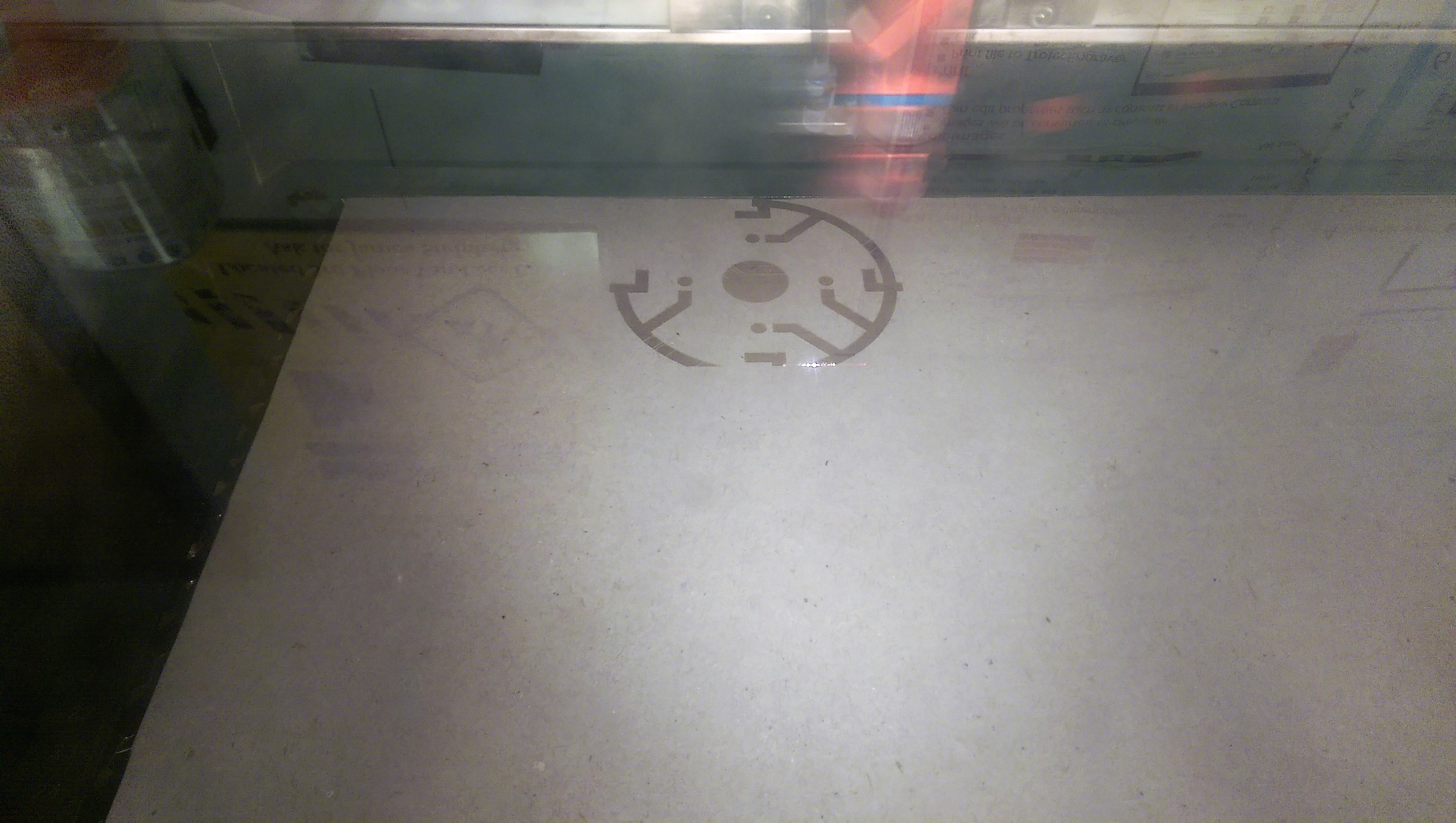
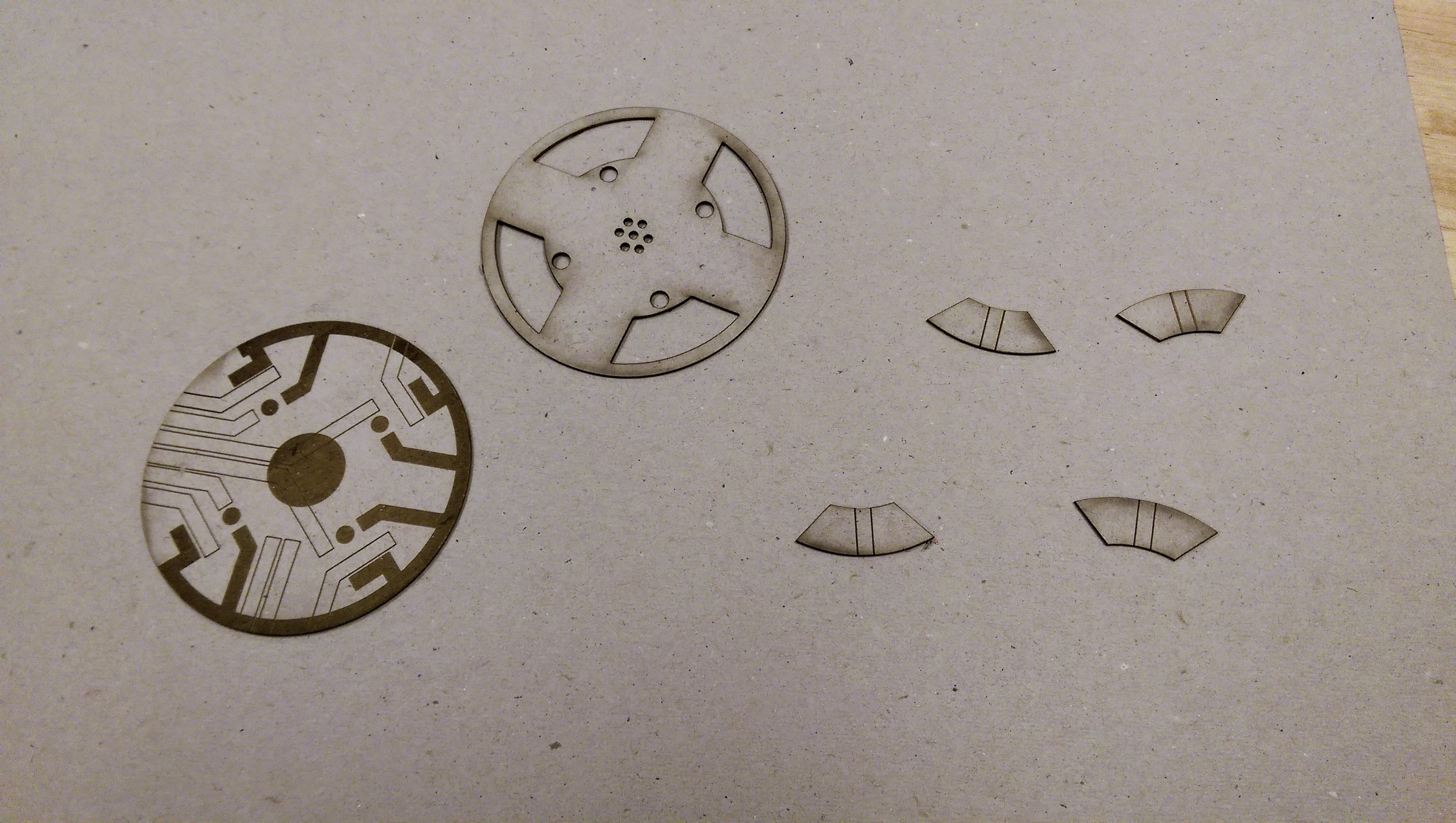
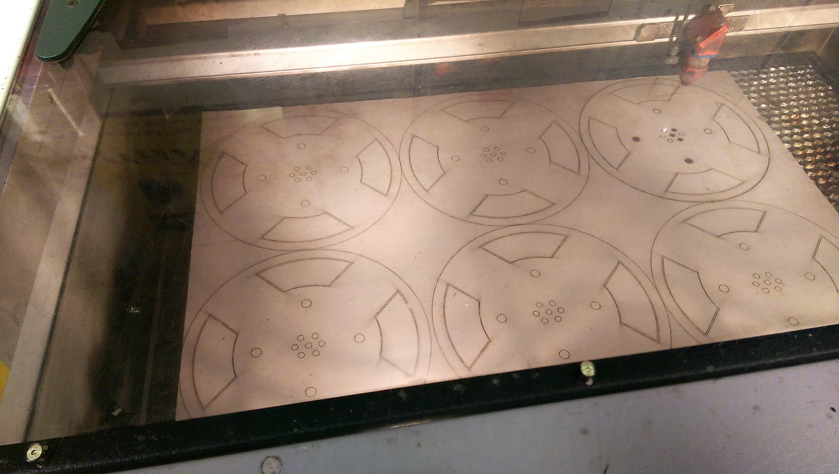
I laser cut these templates from 1 ply chipboard at the Invention Studio, our on campus makerspace. Chipboard templates are pretty sturdy, but if you don't happen to have a laser cutter handy, you can print them on card stock and cut them out with scissors and an X-Acto knife.
For each kit, you'll need one circuit guide, one cover, and 4 buttons.
To Laser Cut your own template:
I've attached the .svg files for your convenience. The each of the two template pieces should be 8" in diameter - check them, because I've been having scaling issues with illustrator lately.
Engrave the red parts, score the black lines, cut through the blue lines.
Downloads
Create Your Ground Bus.
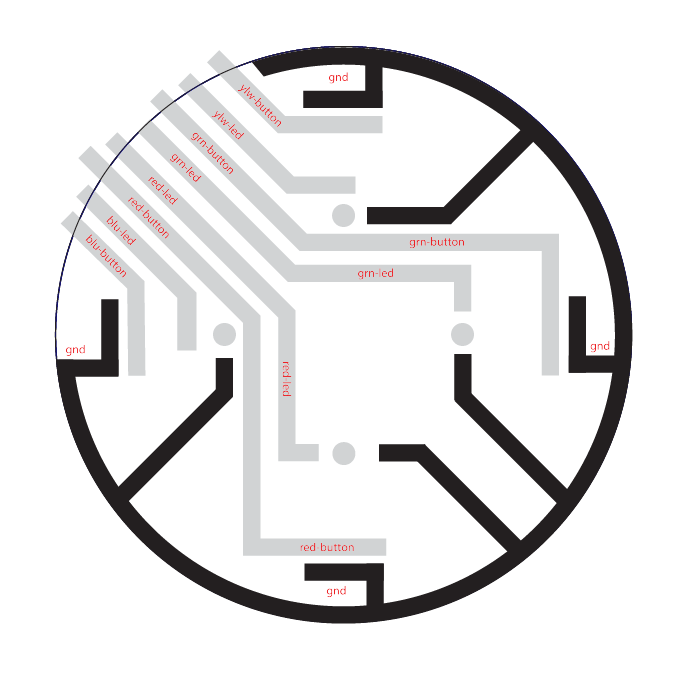
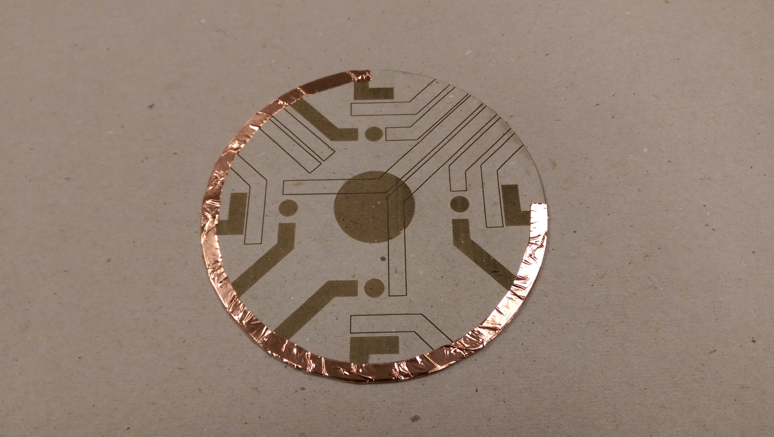
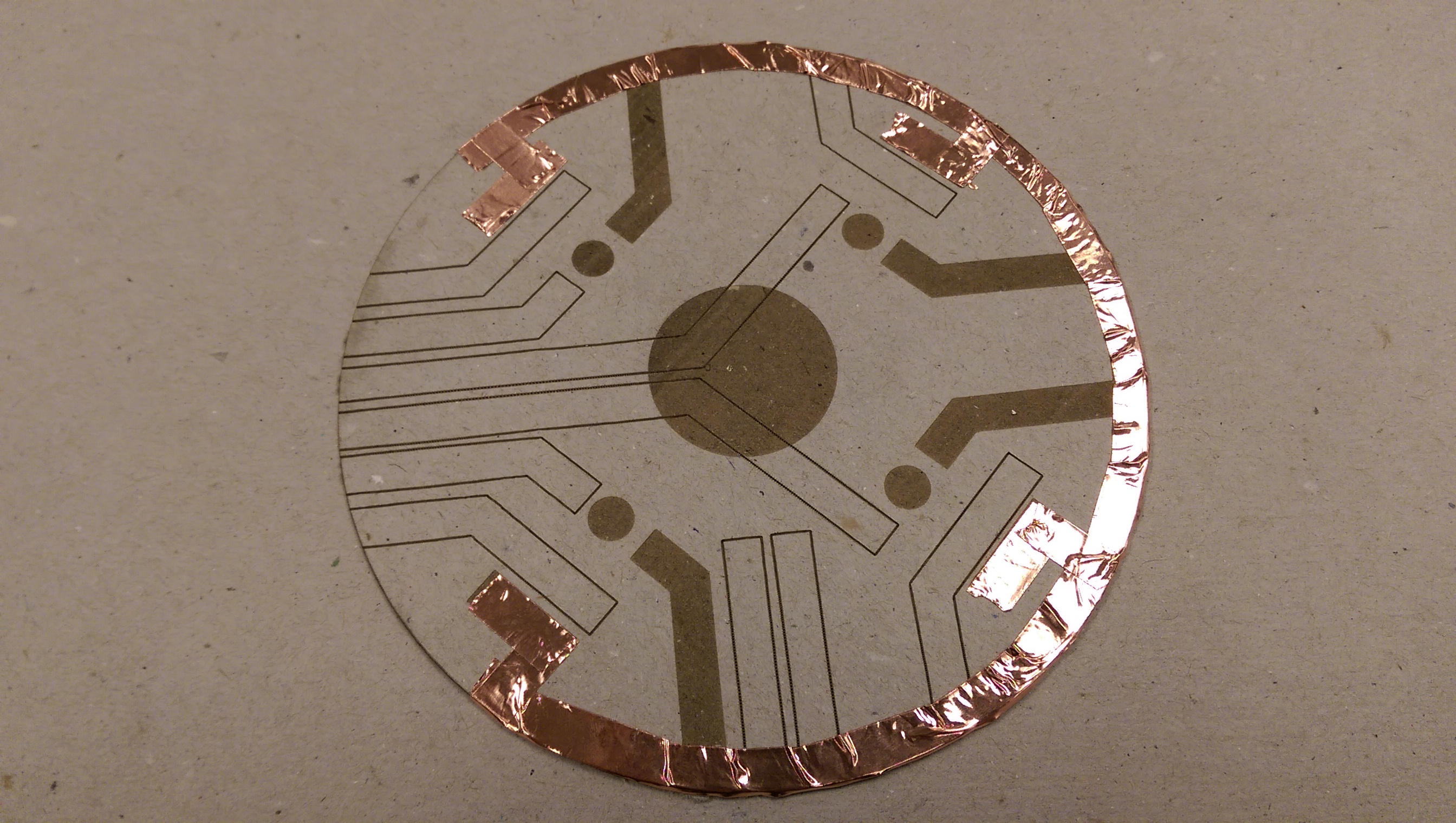
The ground bus on the template is analogous to the one you see on a breadboard. Cover the engraved portion of the circuit guide with conductive tape. You'll have to use more than one strip of tape. To ensure a good electrical connection, make sure any new pieces of tape overlap such that the adhesive side sticks to the next piece of tape.
Create the Button Traces.
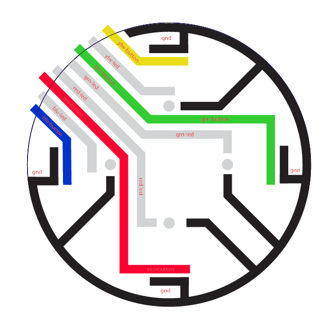
On the circuit template, the button traces are labeled "red-button", "grn-button", "ylw-button", and "blu-button". In my diagram, I've labeled them with their respective colors. Cover those traces with conductive tape. You'll have to use more than one strip of tape. Overlap tape to make sure that the trace has a solid connection.
These traces will be bridged later with each of the buttons.
Create the LED Traces.
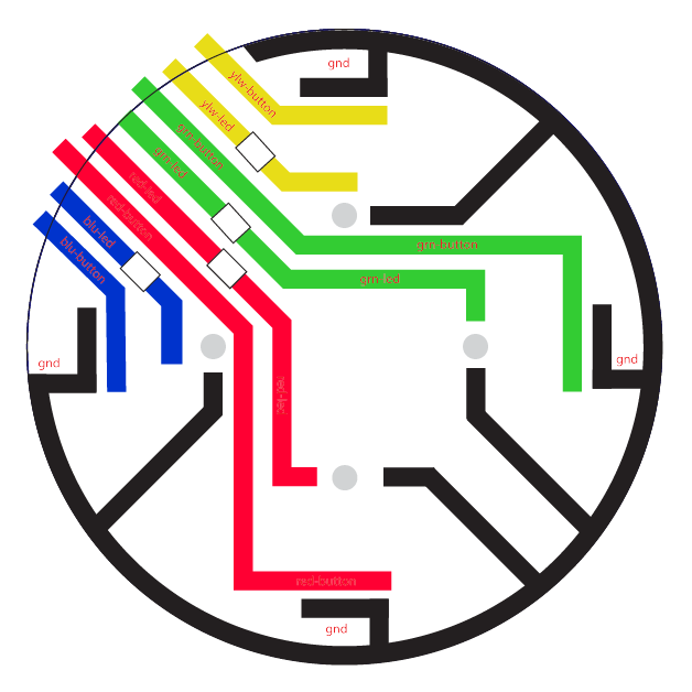
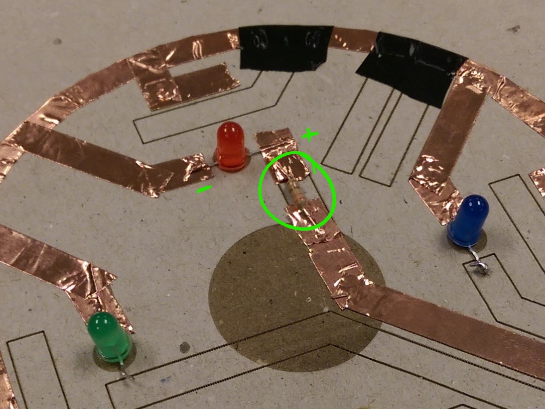
The LED traces should be the last uncovered area on the template. These represent the positive side of the LED, and each lead will require one of the 330 ohm resistors inline to protect the LED.
To do this, you'll need to lay down copper tape on the trace, leaving a gap in the tape for the resistor. Place the resistor over that gap in the tape, and put copper tape over each lead of the resistor. Because copper tape doesn't make for the strongest connection, you'll want to press and smooth the top layer of tape down.
Add the LEDs.
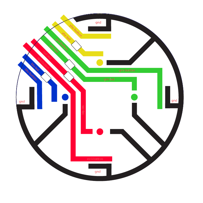
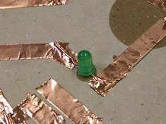
Bend the leads of your 4 LEDs such that they stand up on a flat surface on their own. Place each LED on its engraved circle on the template, lining up the leads accordingly. The lead from the flat side of the LED is the anode, and it connects to the ground bus. To secure it in place, you'll firmly sandwich the ground lead in between two pieces of copper tape.
The other lead connects to its corresponding LED trace, like "ylw-led" in my diagram. This lead will also get sandwiched between the copper lead and a new piece of copper tape.
Smooth all of the tape over the leads of the LEDs, to create a stronger electrical connection.
Add Jumper Wire Connections.
You'll need 9 pieces of wire for this - one for the ground bus, one for each button trace, and one for each LED trace. Sandwich one end of each length of wire between an existing trace on the circuit guide and another piece of copper tape. Smooth the tape over the wires, so that there's a good electrical connection.
Even with a good connection, copper tape can be finicky and fragile. Be careful when moving your Simon game around.
Put the Cover on the Circuit Guide.
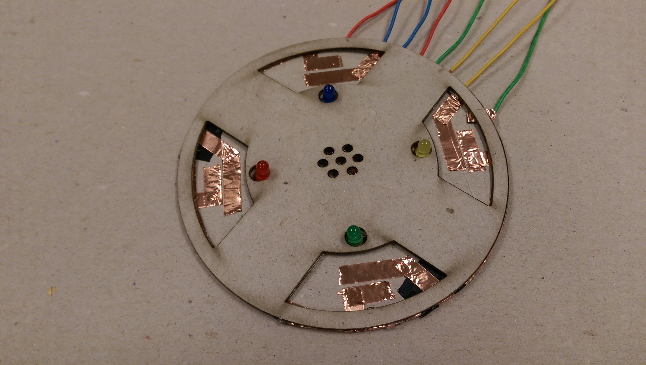
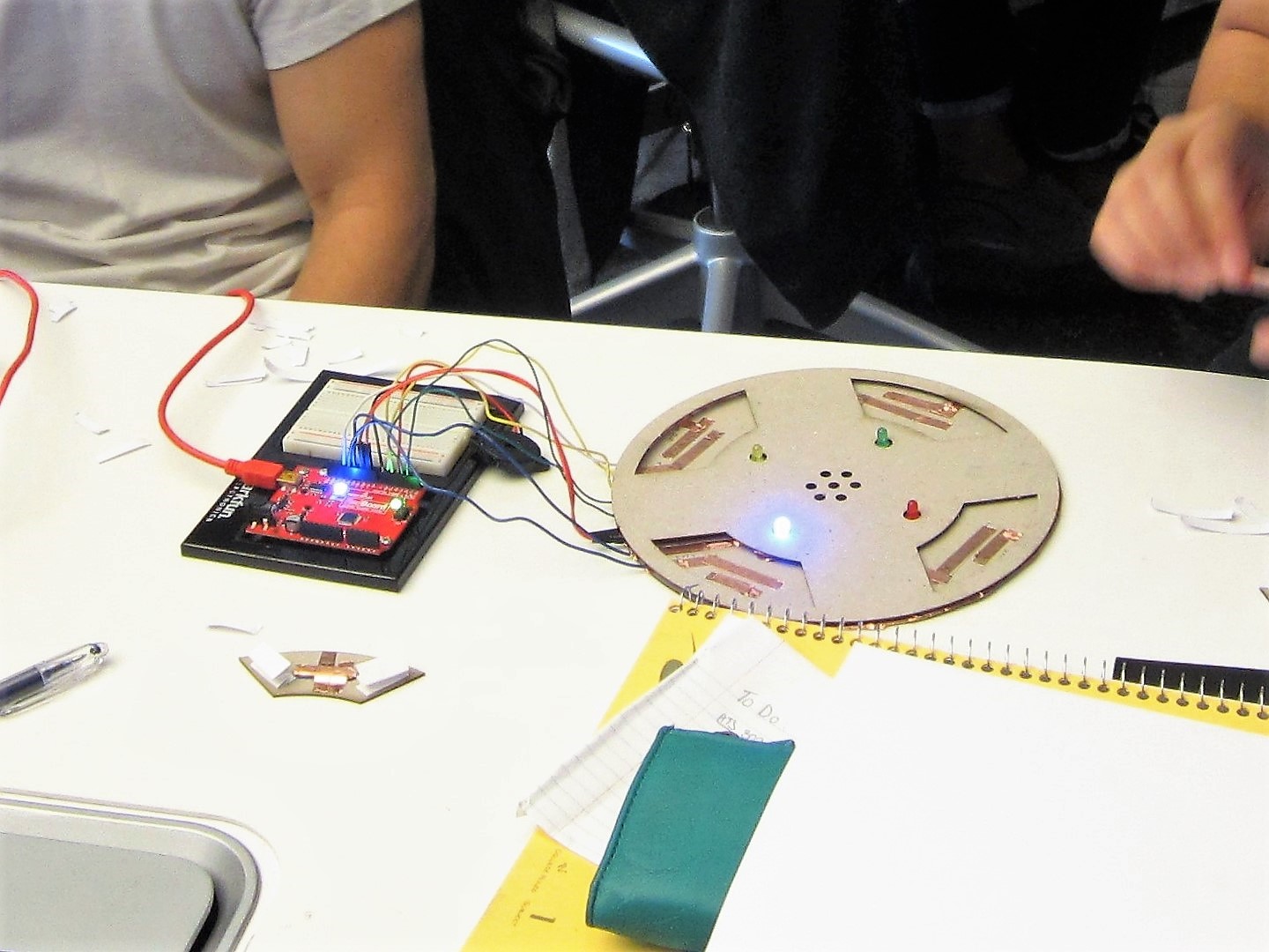
Not really much to this one, eh?
I usually do not glue the cover down. If you need to troubleshoot later after you've glued it, you'll wreck the entire circuit trying to pull the cover off.
It's at this stage that you can begin to test your connections, if you want.
Create the Buttons.
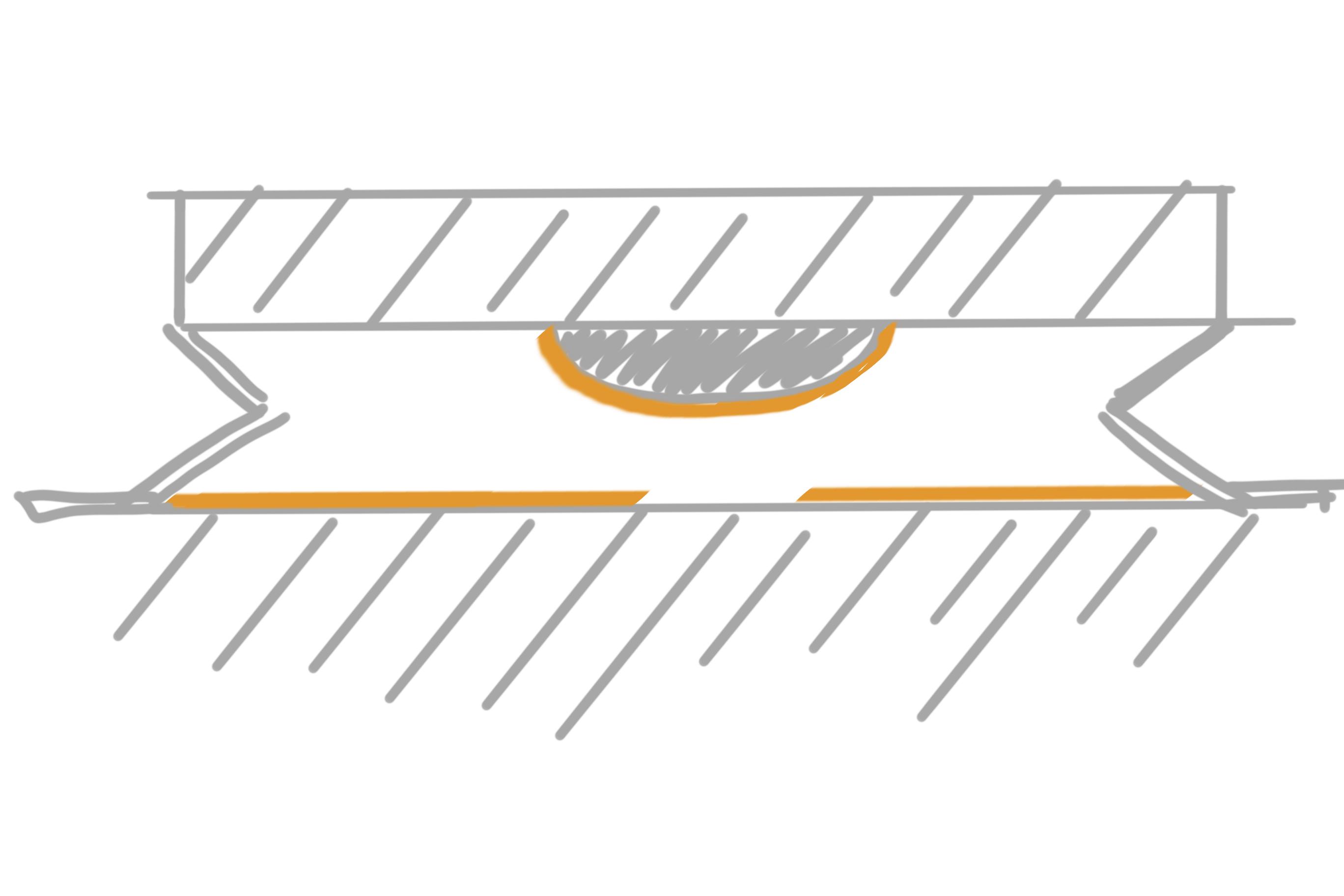
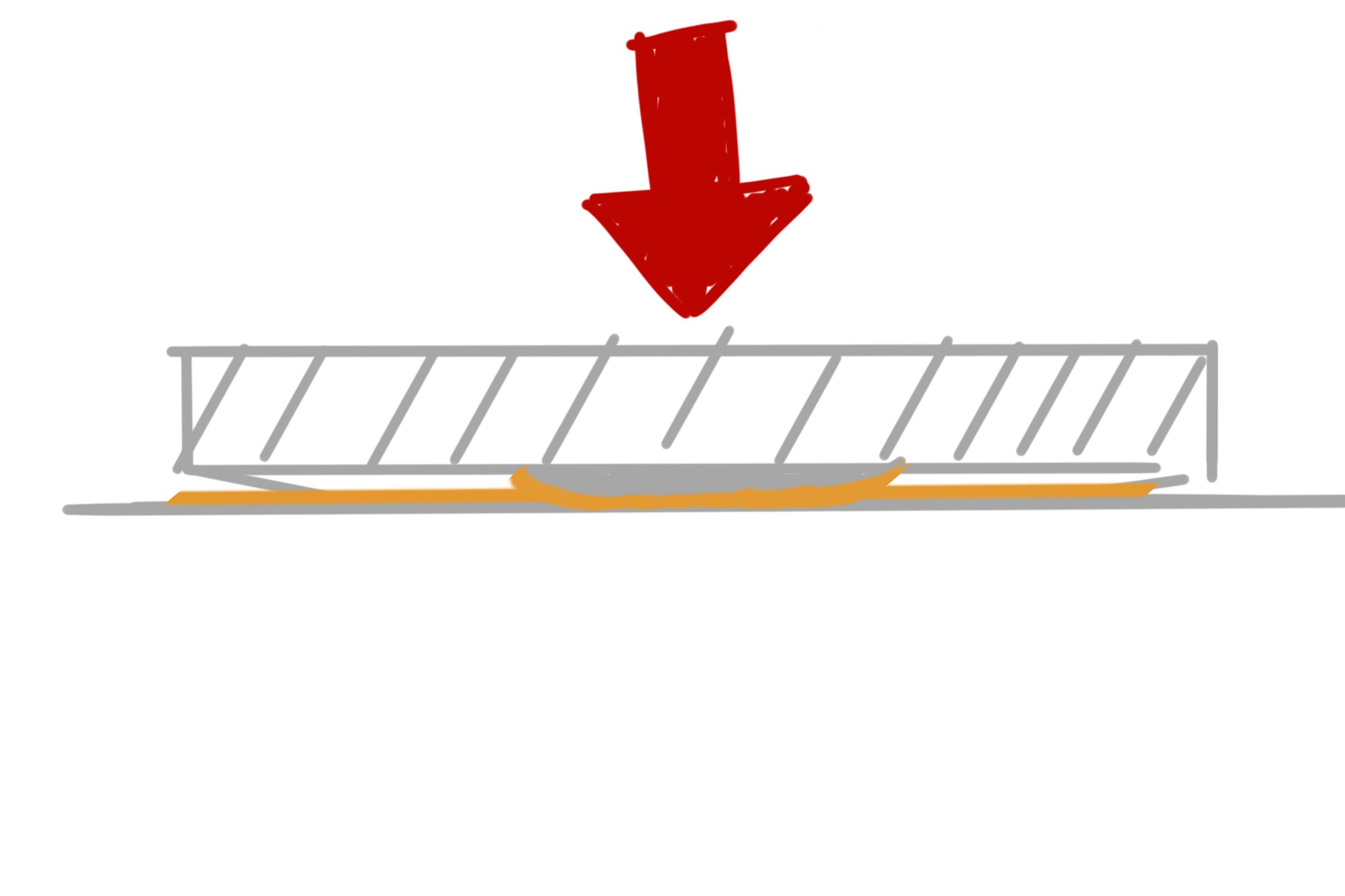
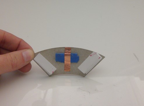
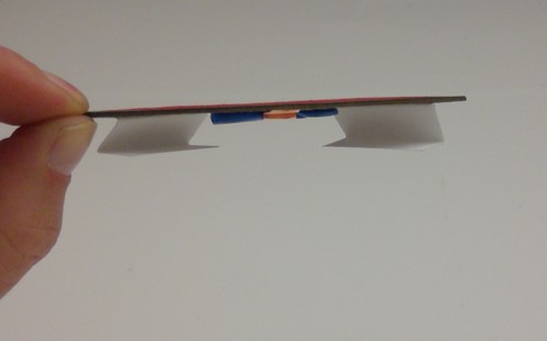
Place copper tape on the underside of each of the chipboard buttons as shown in the picture. This is what will close the circuit between the button and ground pins on the Arduino. It helps if the tape is slightly raised off the surface of the button. That provides pressure and a more solid connection.
Make 8 little fan fold pieces out of your paper or card stock. These will act as your springs to keep the circuit normally open. Glue the folded paper to the buttons as shown.
Use your glue stick to adhere the bottom flaps of your fan fold pieces to the circuit guide. Try to be precise with your placement of the buttons. If you move them after the glue has dried, you'll end up breaking any copper tape (and the electrical connection) of whatever traces were underneath.
Color in the tops of the chipboard accordingly with your markers.
Hook Up Arduino.
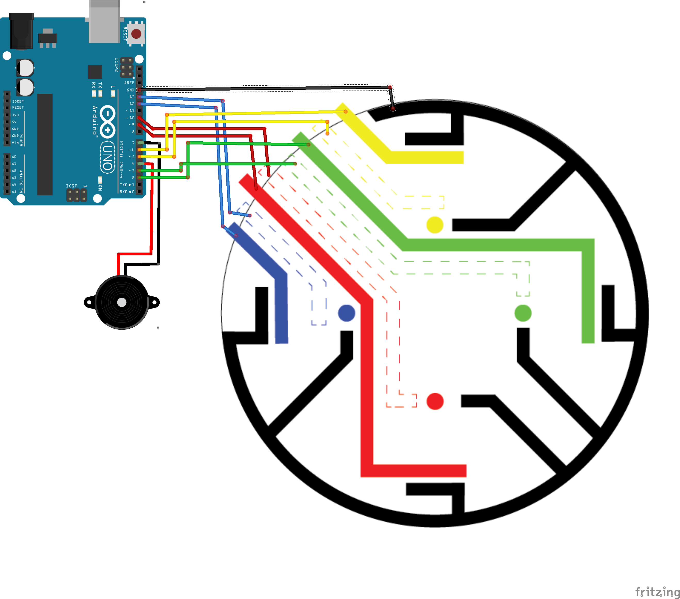
Plug each of the jumper wires into their corresponding space in the Arduino.
- 2: Green button
- 3: Green LED
- 4: buzzer wire 1
- 5: Yellow LED
- 6: Yellow Button
- 7: buzzer wire 2
- 9: Red Button
- 10: Red LED
- 12: Blue Button
- 13: Blue LED
- GND: Ground bus
Upload the Code.
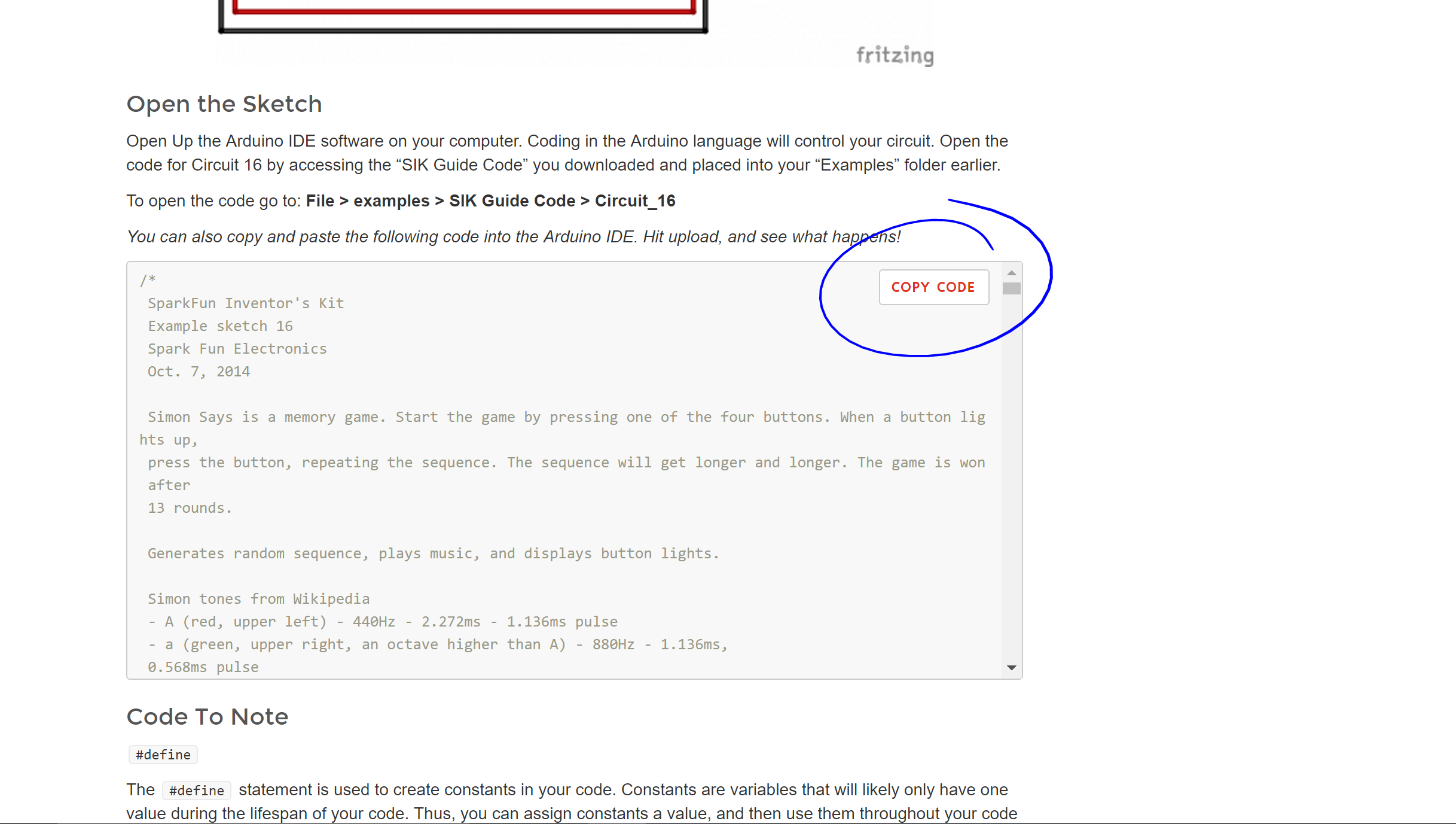
Instead of reinventing the wheel and rewriting a bunch of code, I used the code from this Sparkfun tutorial:
https://learn.sparkfun.com/tutorials/sik-experimen...
Open up a new sketch in the Arduino IDE. Hit the copy code button on the Sparkfun page, and then paste that code in your sketch. Upload it to your board, and you should be good to go!