PVC Chair Assembly
by sportschild1234 in Workshop > Home Improvement
2808 Views, 24 Favorites, 0 Comments
PVC Chair Assembly
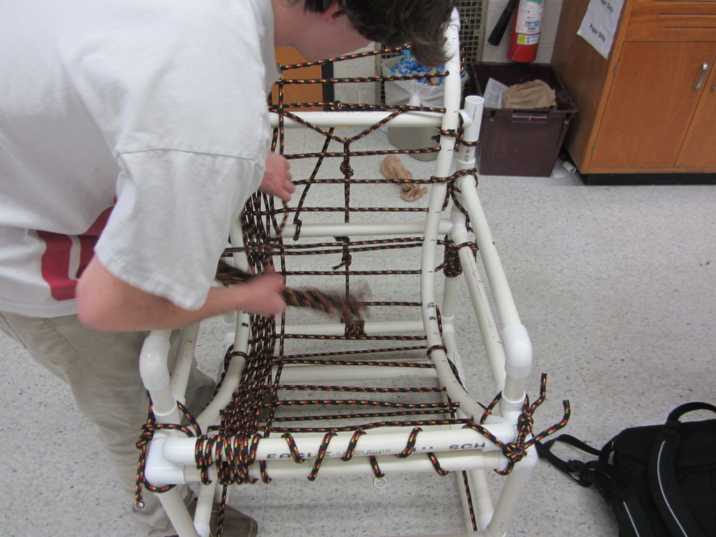
This instructable is about how to make a PVC Chair. There are specific materials needed for this chair. The chair is made up of solely PVC material. The diameter of all the PVC pieces is 1 inch.
There are 3 major steps to these PVC chairs. They were built on solidworks as 3D model, built up as miniature life sized models using 3/16 wooden dowels, and then the final build is the actual life sized model using PVC pipe.
The PVC chair was built upon a program solidworks has multiple steps on how to do it. How to mate PVC, how to make PVC, and sub assemblies for the chair.
Solidworks Part I: Create PVC
How to make PVC:
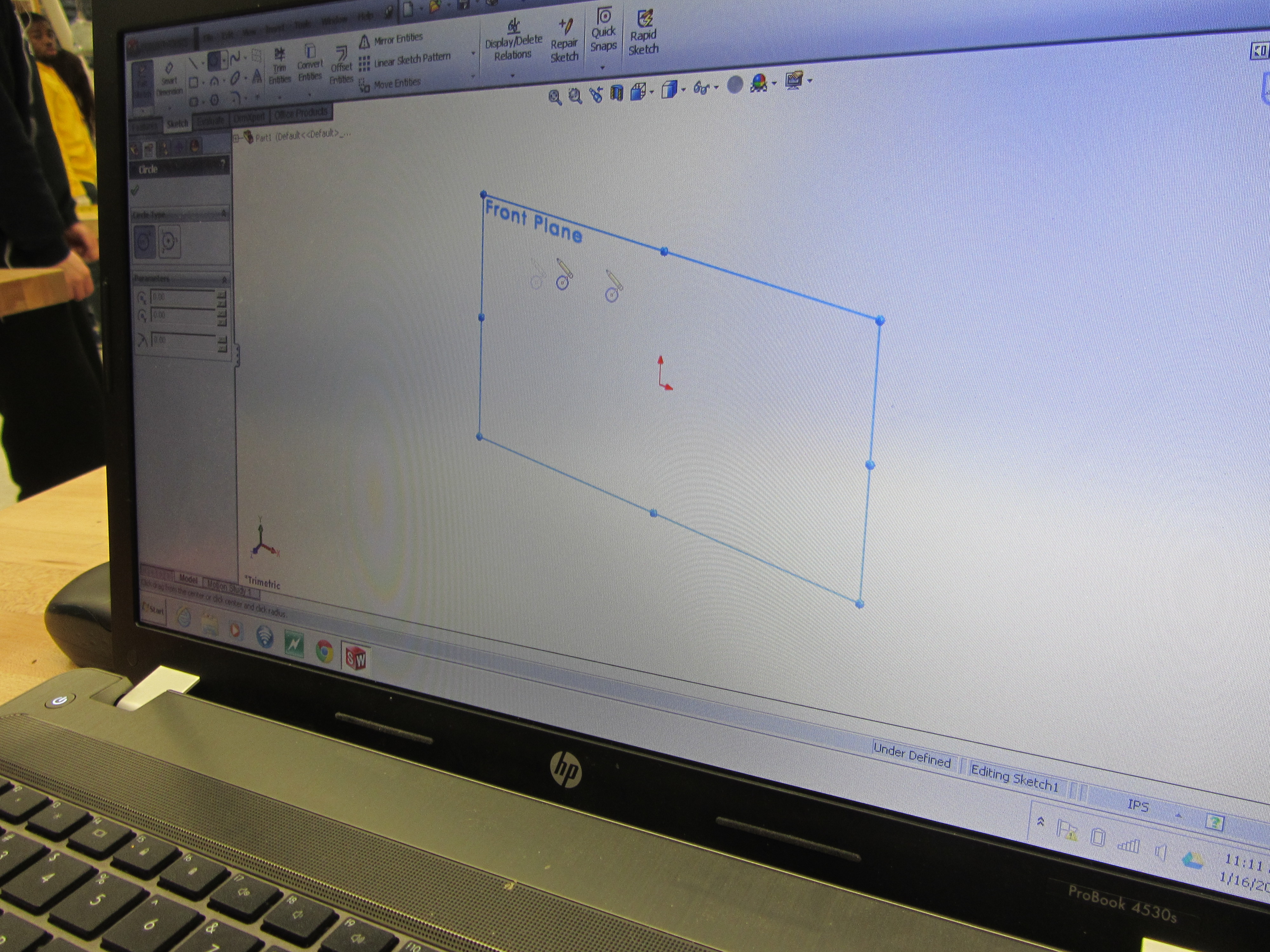
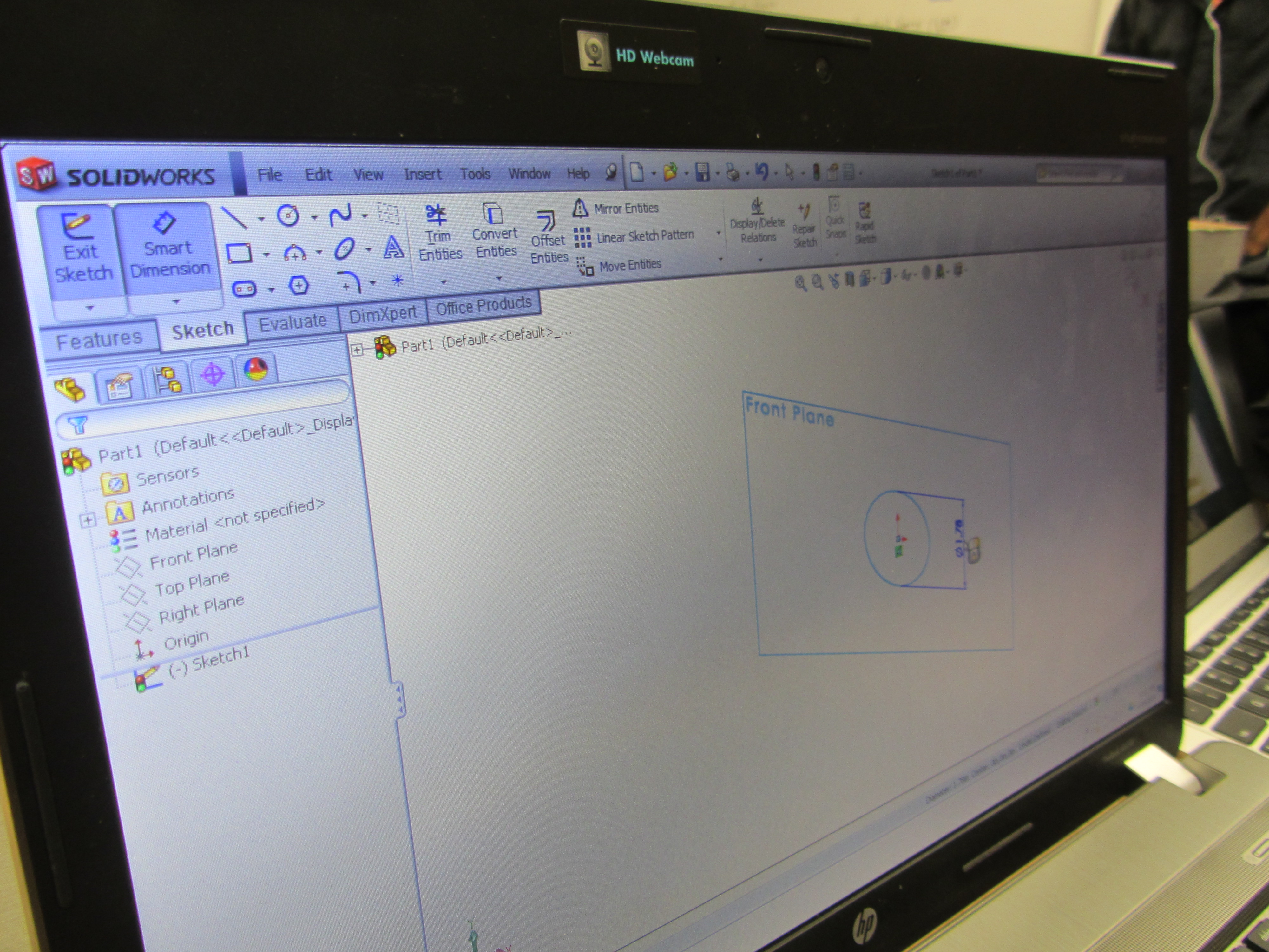
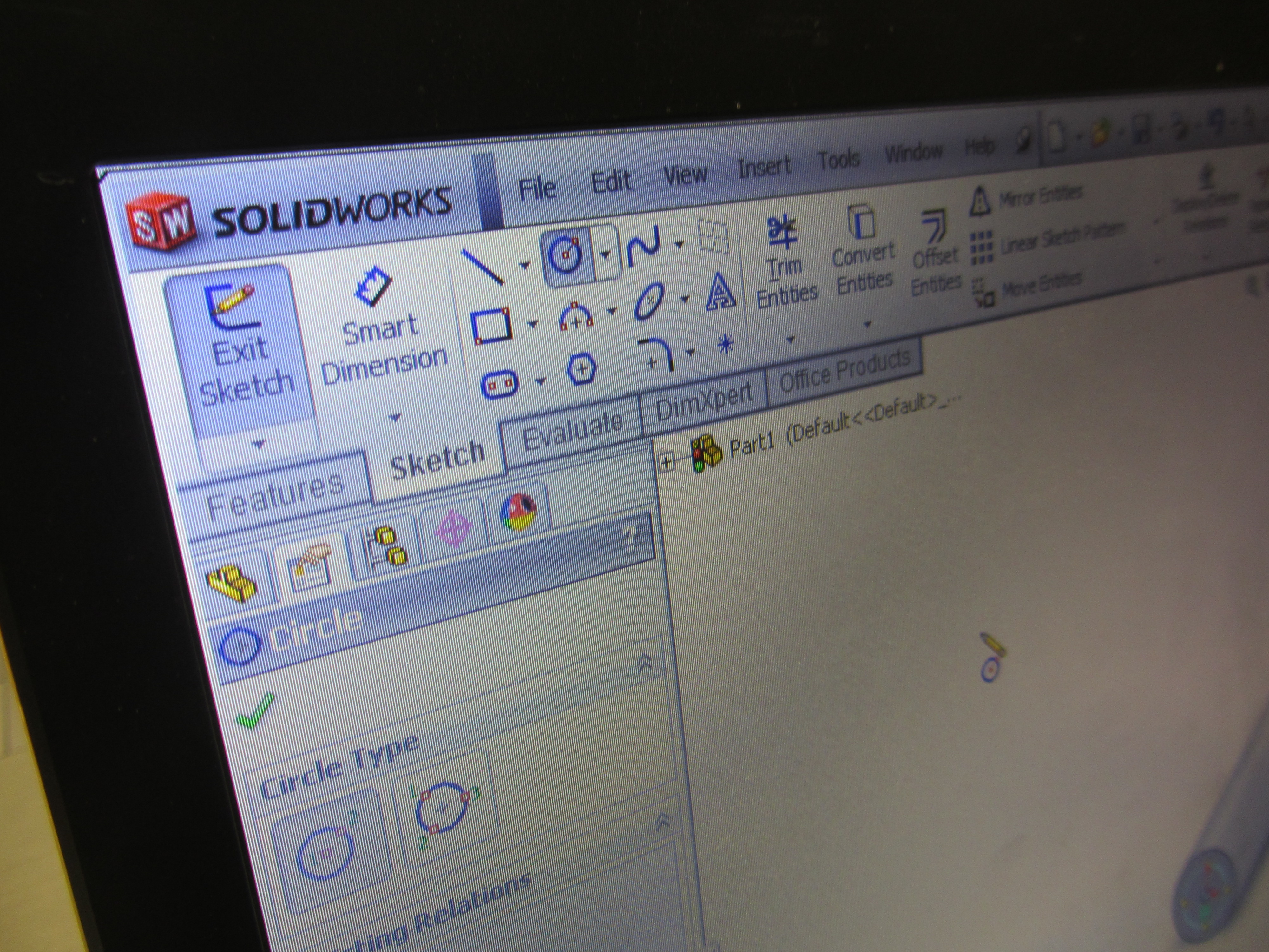
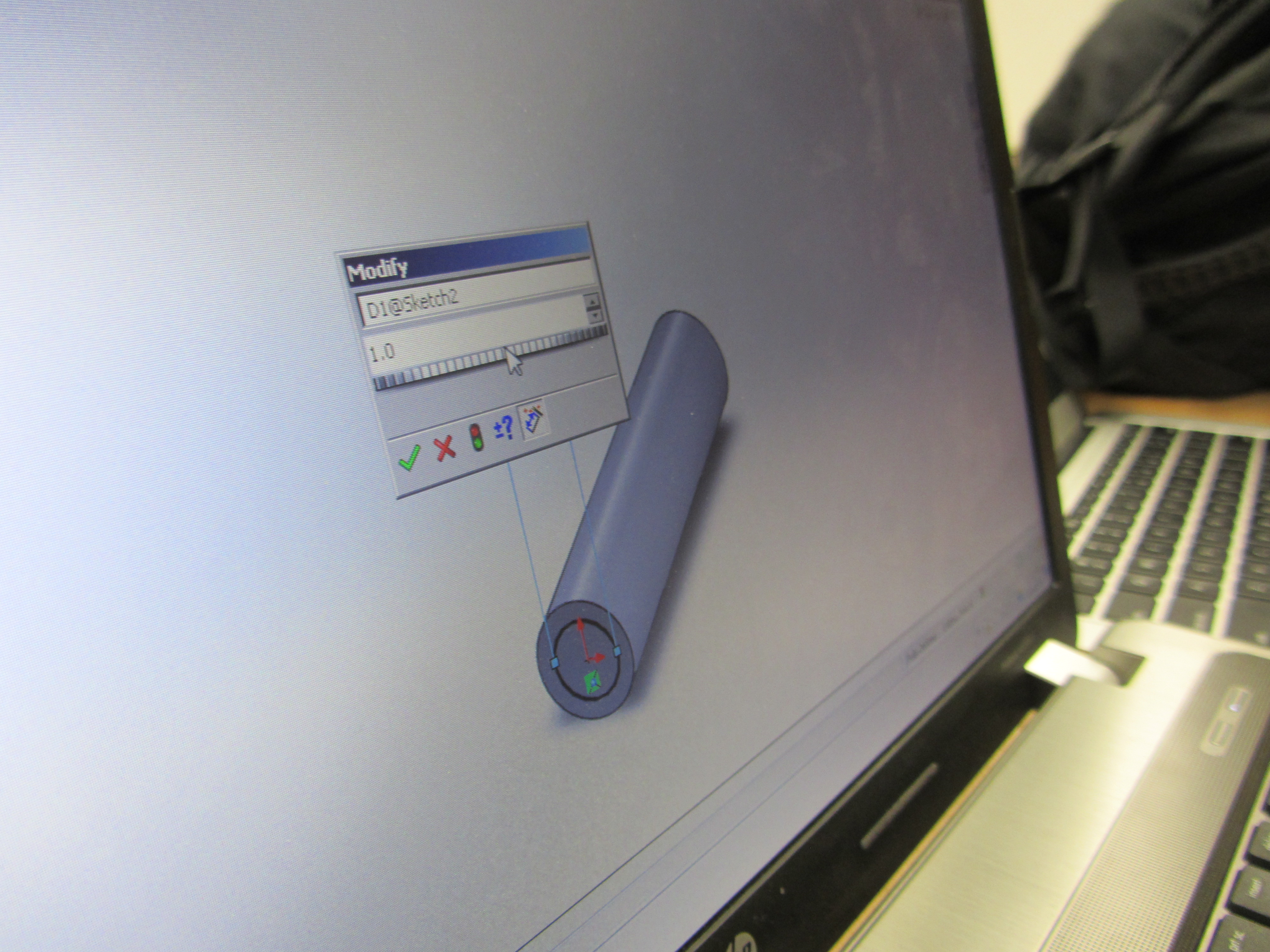
Create a sketch of a circle and smart dimension it with the outter diameter.
-Open Solidworks > click file > click new > click part and then click ok > click sketch in the top left corner > click front plane >
-click circle which is located in the 4 by 3 grid of options
-click on the point of origin in the sketch which will light up orange and drag out
-go to the top left corner and click smart dimension
-go back to the circle and click on the outter edge which will light up in orange like the point of origin did
-move the mouse to the right or left of the circle and click
-a window will pop up that says modify and in that one would put the dimension of how big they want the diameter of the circle
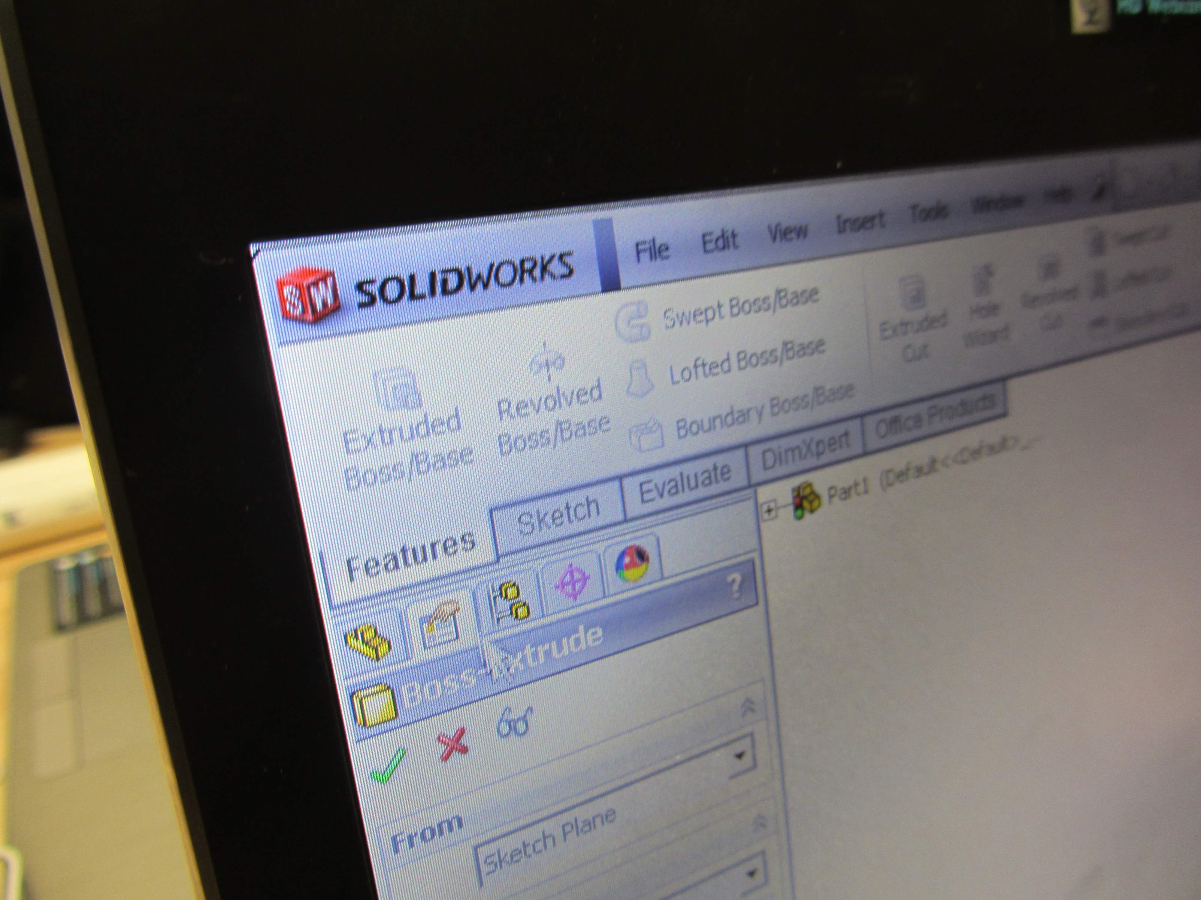
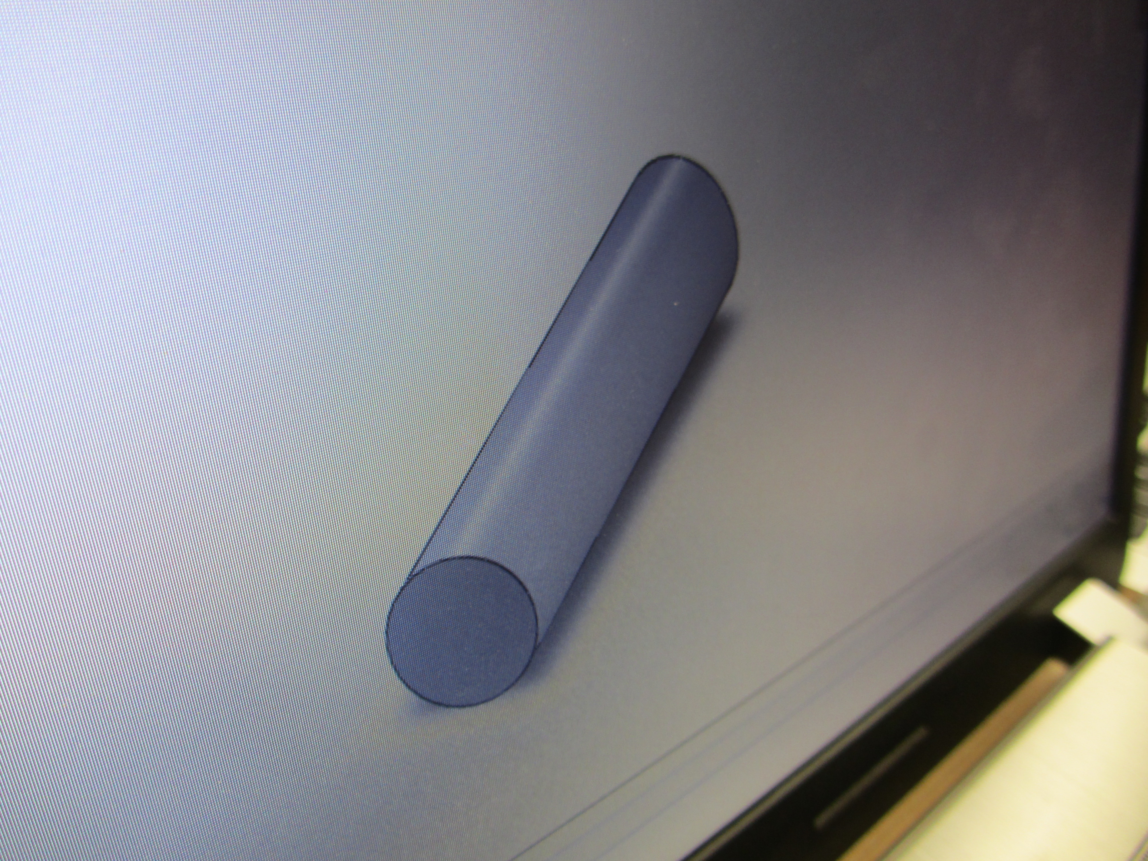
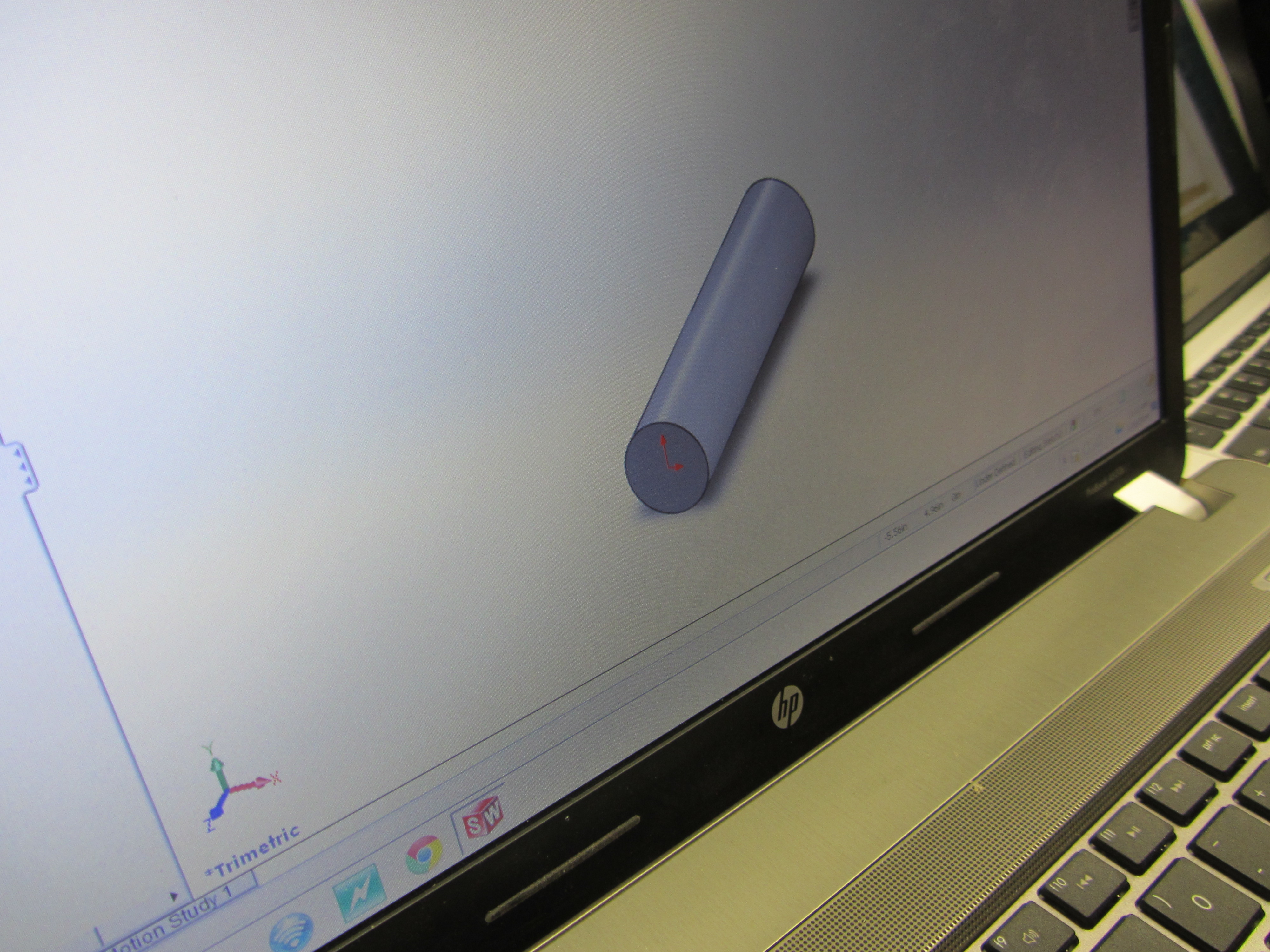
After this extrude the circle to what ever length it's called for.
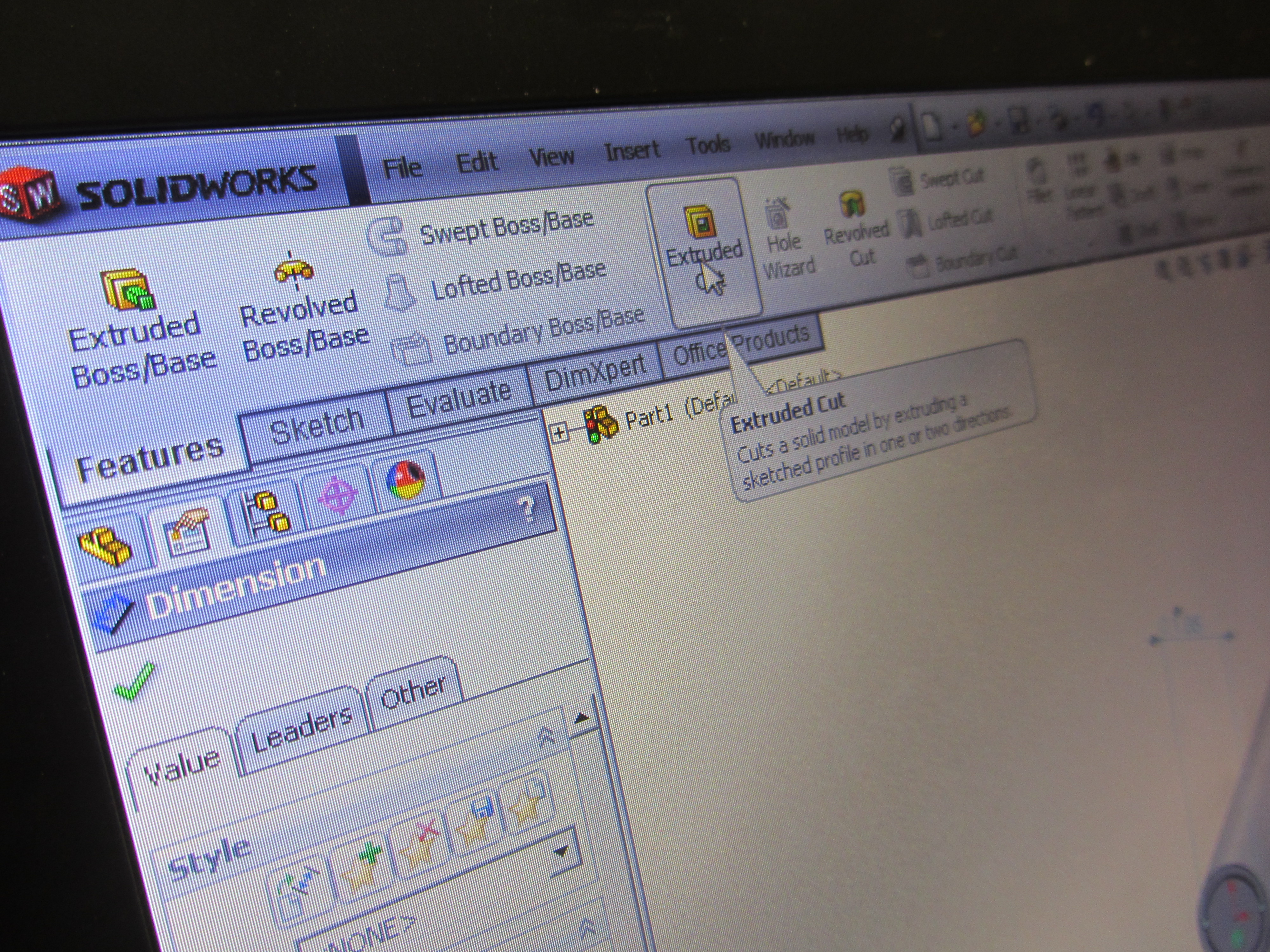
-go into the section called features and click "Extruded Boss/Base" >
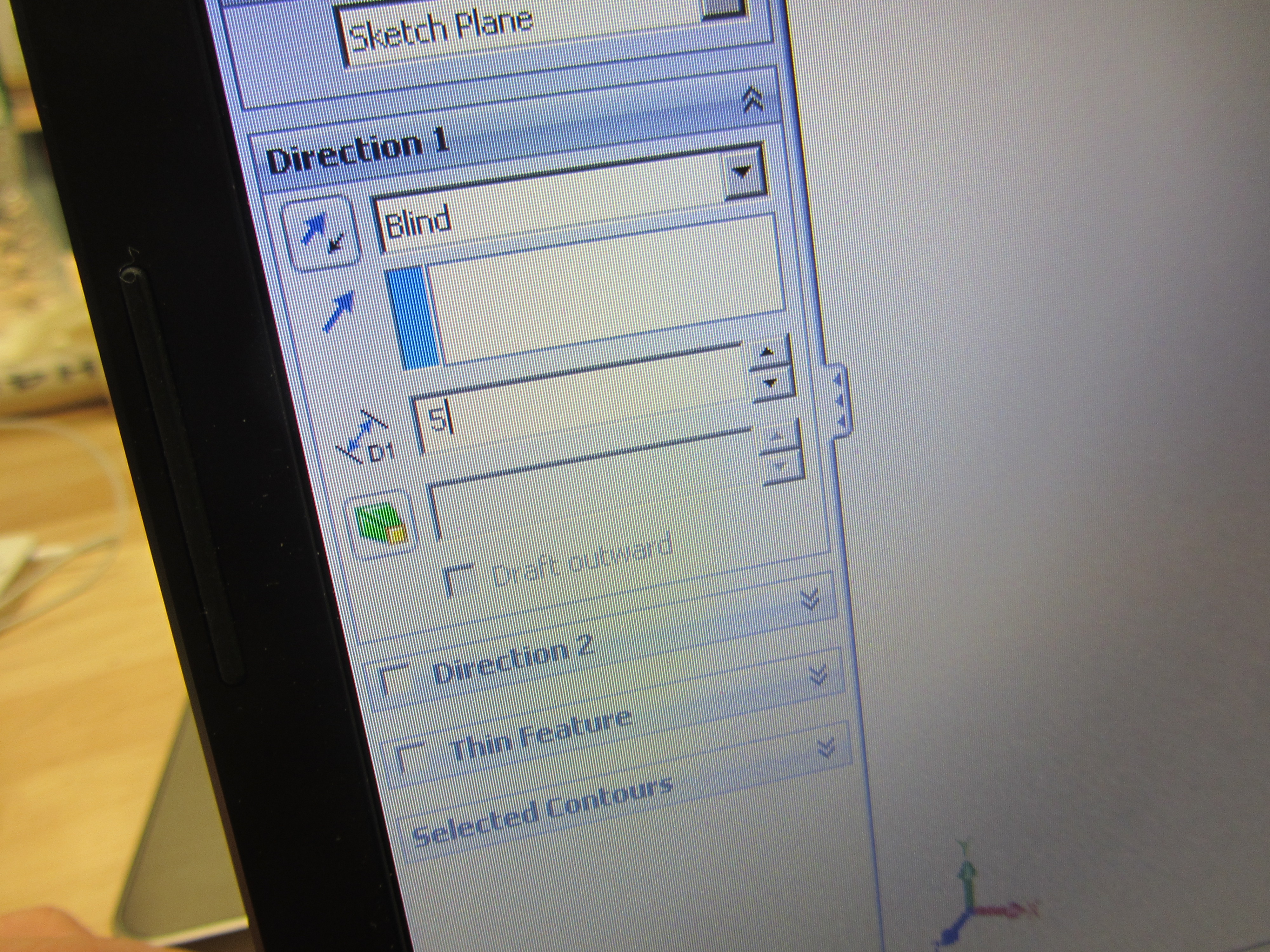
-a template on the left side will come up that has different titles in it. look under the title that is labeled direction 1 and a number will be highlighted in blue. that number represents how long you want the cylinder to be. change the number according to how long you need your cylinder to be
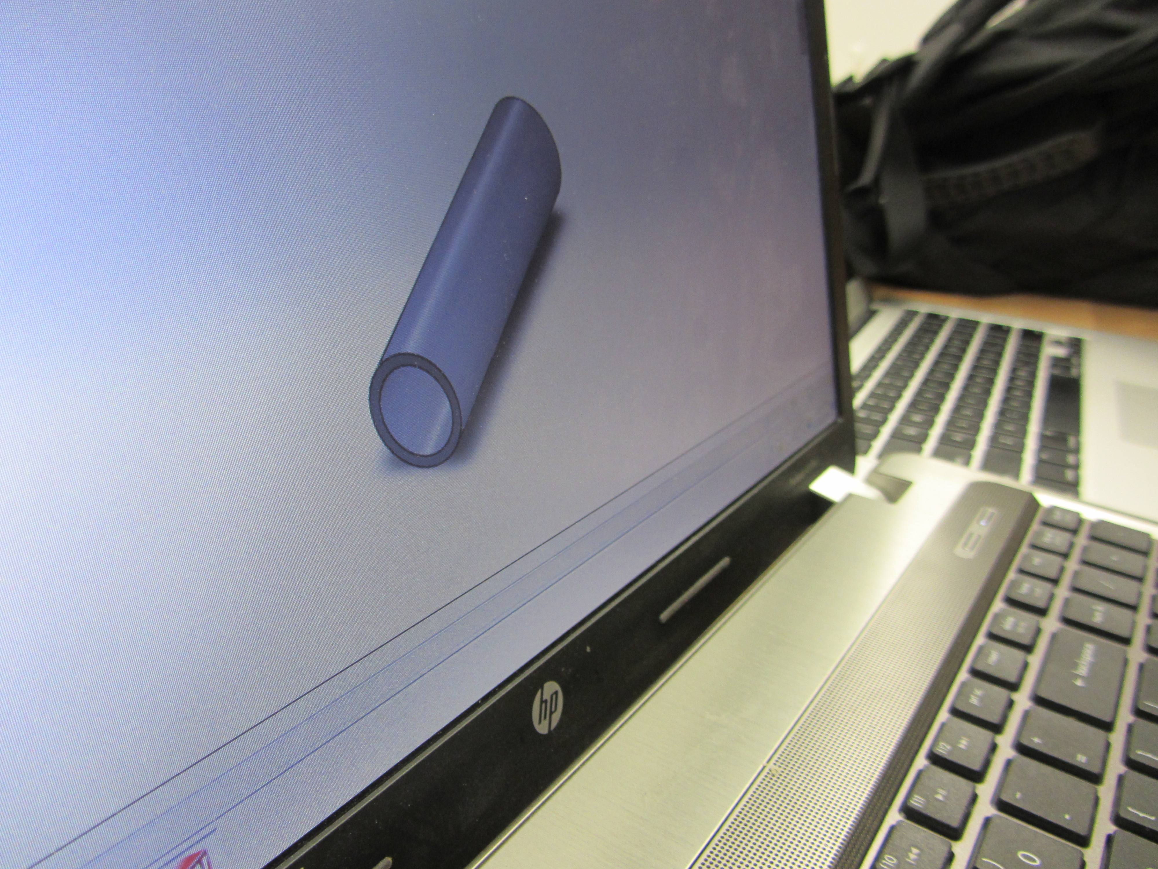
At this point the cylinder is fully made but now there has to be a cut through the cylinder to make it hollow.
-go back into sketch select circle and then find the origin point on one of the faces of one of the end pieces of the cylinder.
-don't let the circle go outside of the original face. once the appropriate circle is created to your liking click with your mouse.
-go to features then find extruded cut and the hollow cylinder will be created
-where the cylinder is placed to where you can see it click the green check in the top right corner
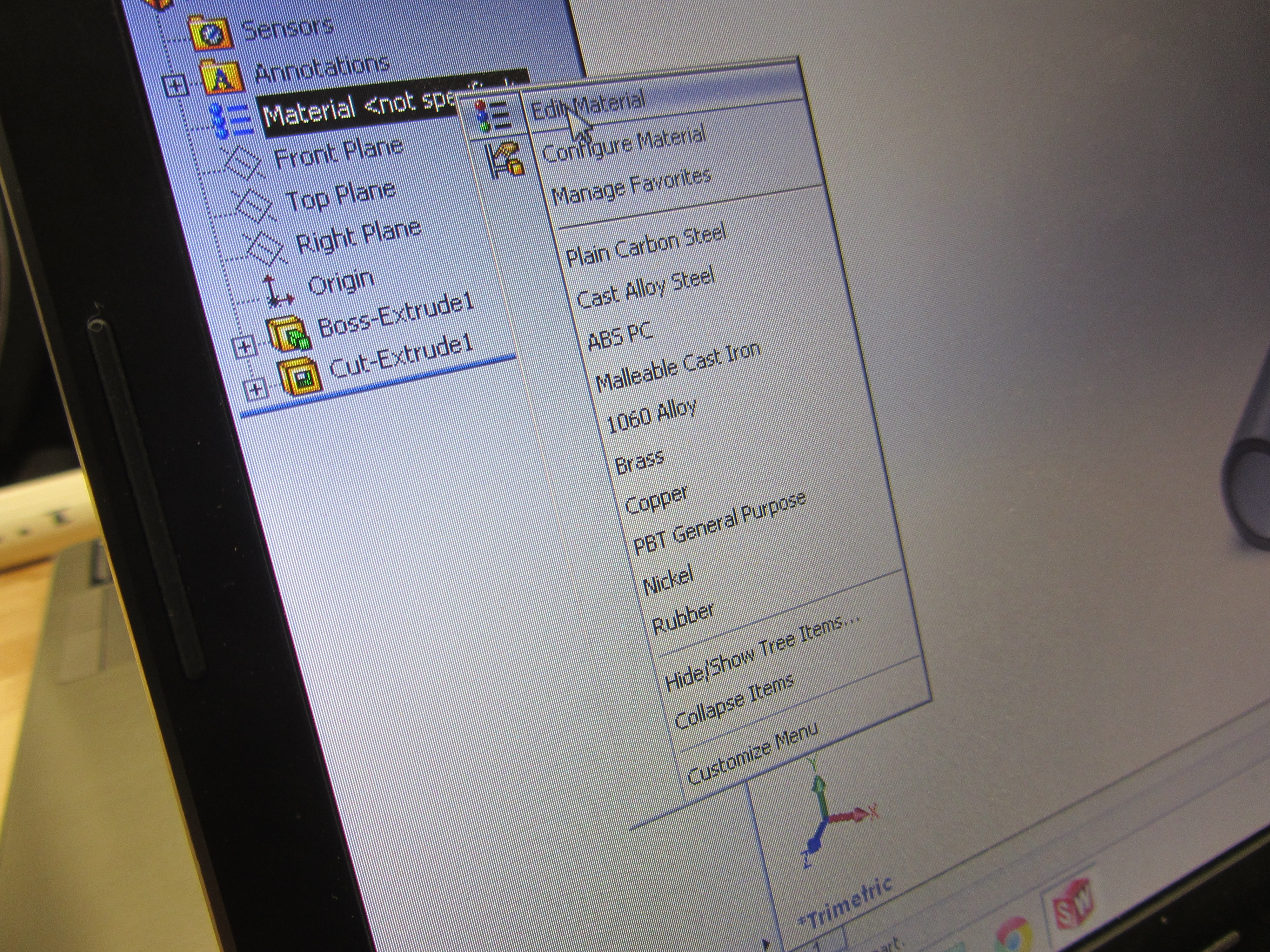
The material has to be changed to PVC and the process of making the PVC pipe is complete.
-on the template on the left side right click on "Material " under the section called "Annotations"
-under the "Plastics" section click "PVC Rigid" then click on "Apply" and lastly exit the materials window by clicking on the top right corner where the inboxed "X" is located.
Solidworks Part II: How to Mate a Piece to a Fitting
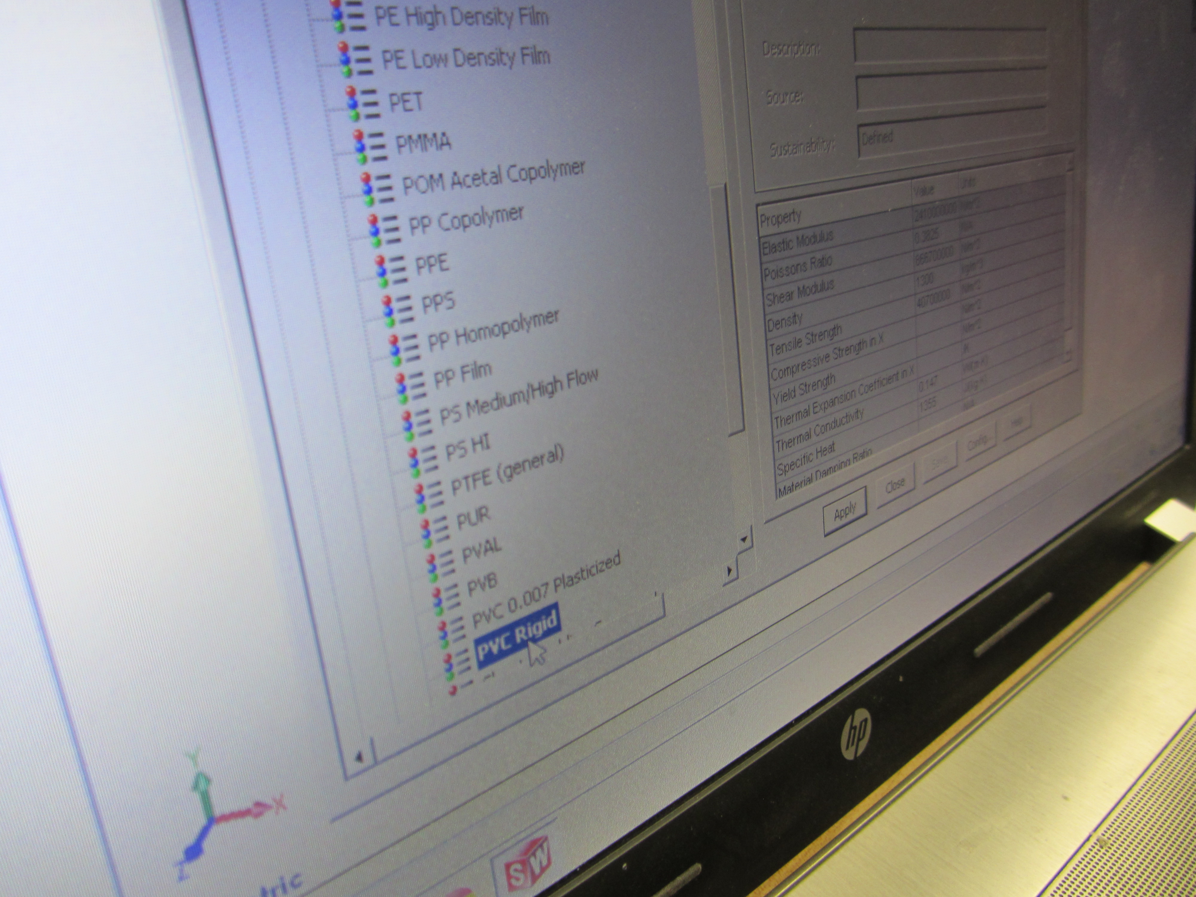
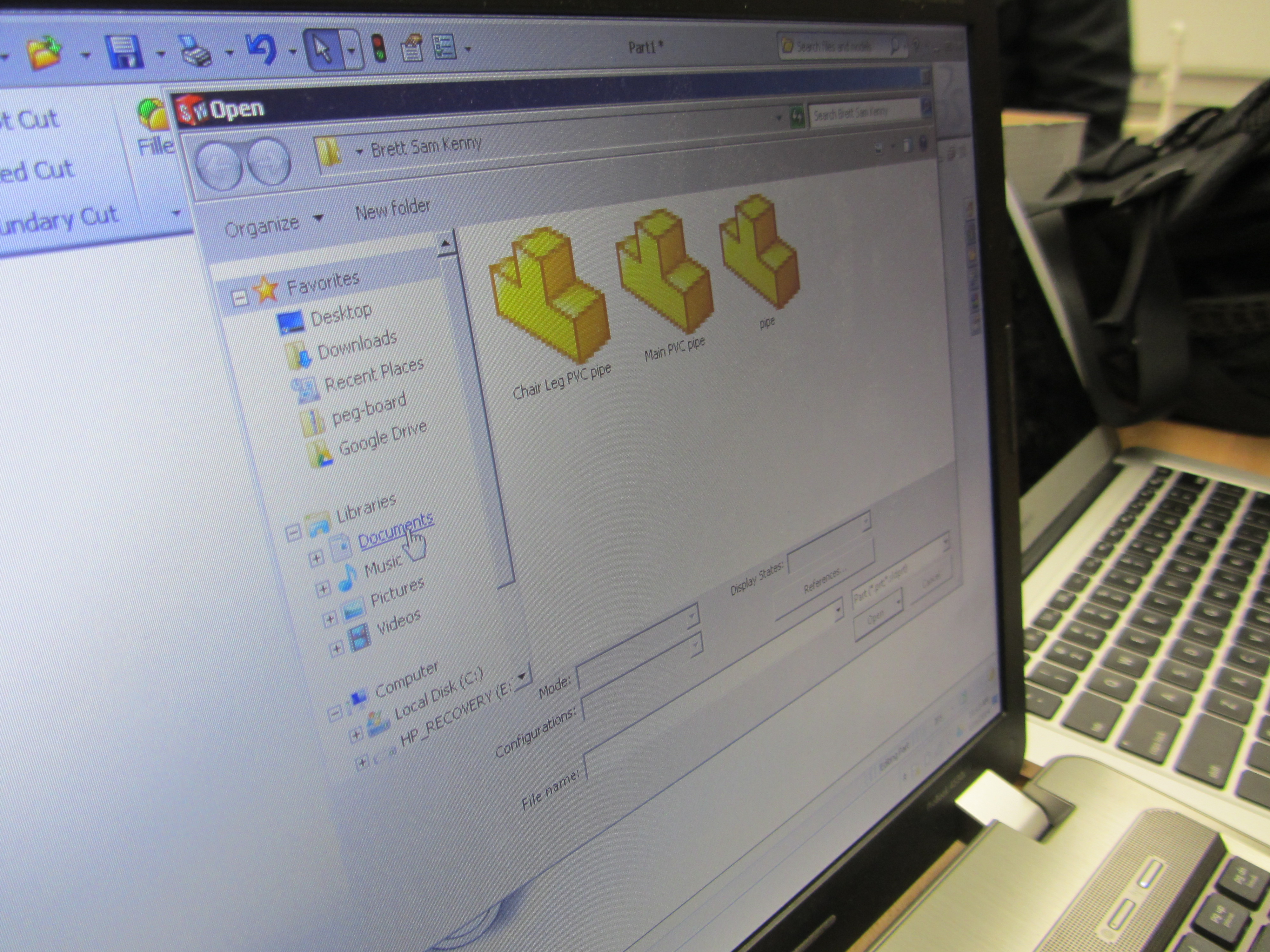
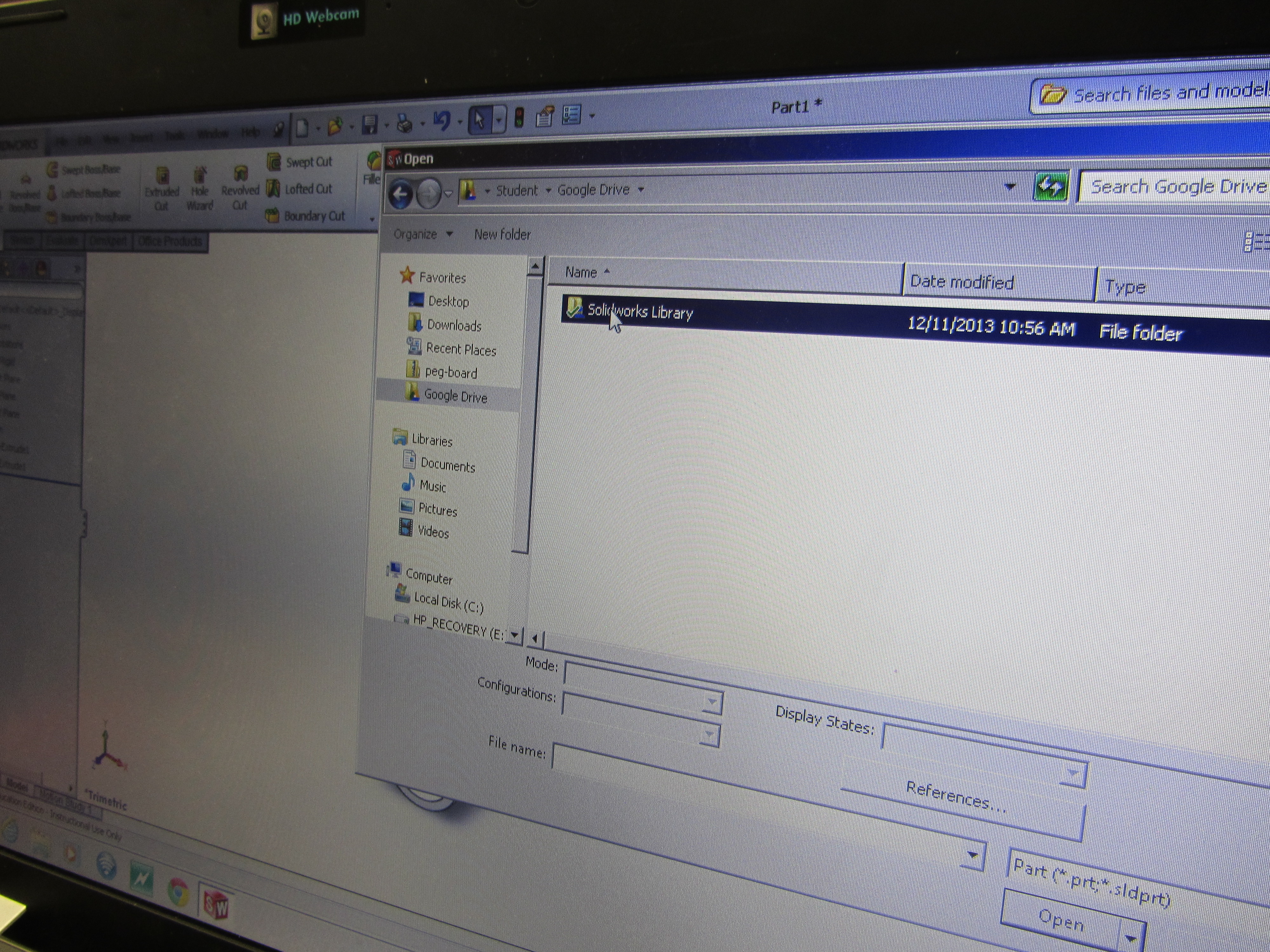

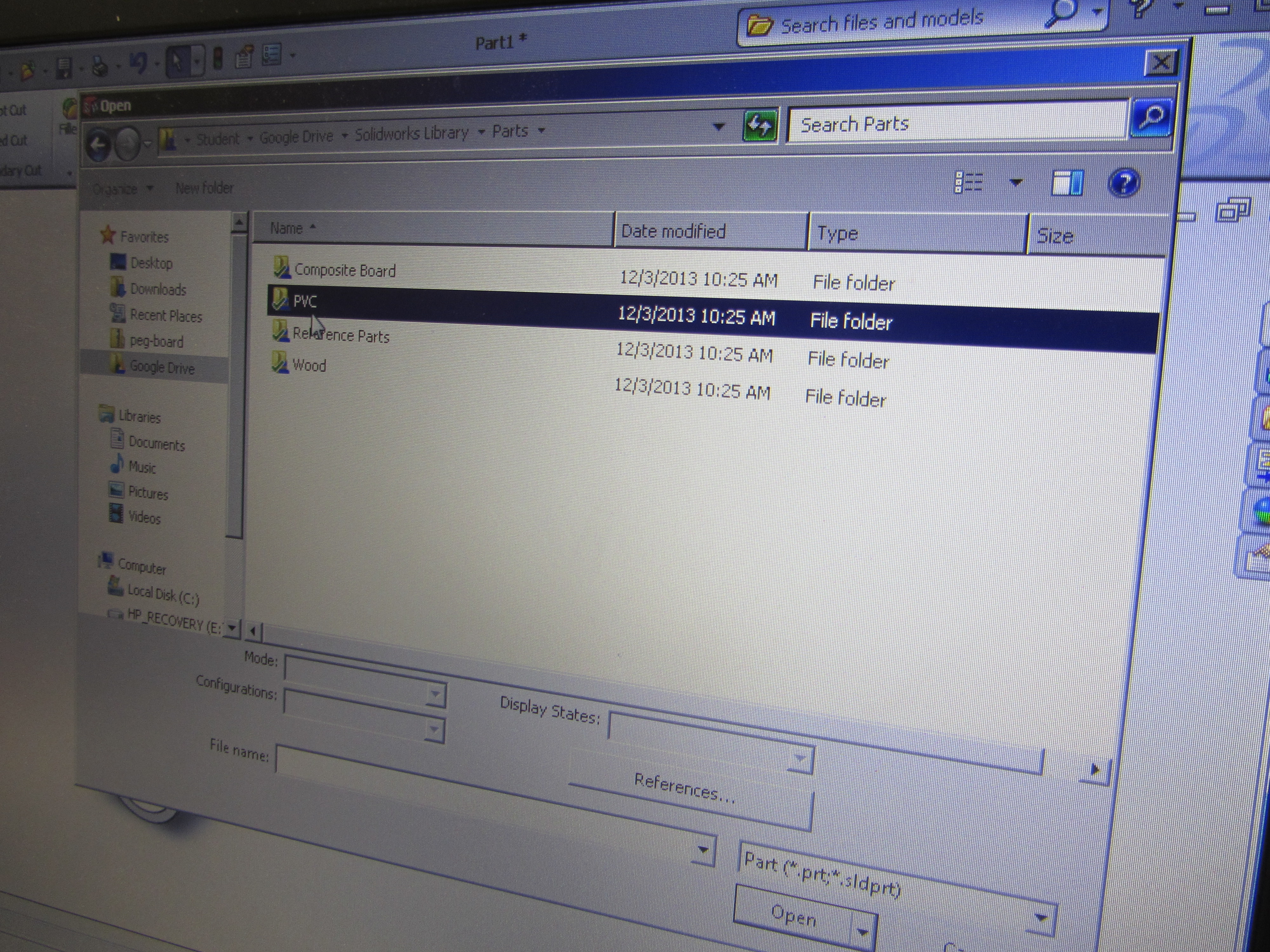

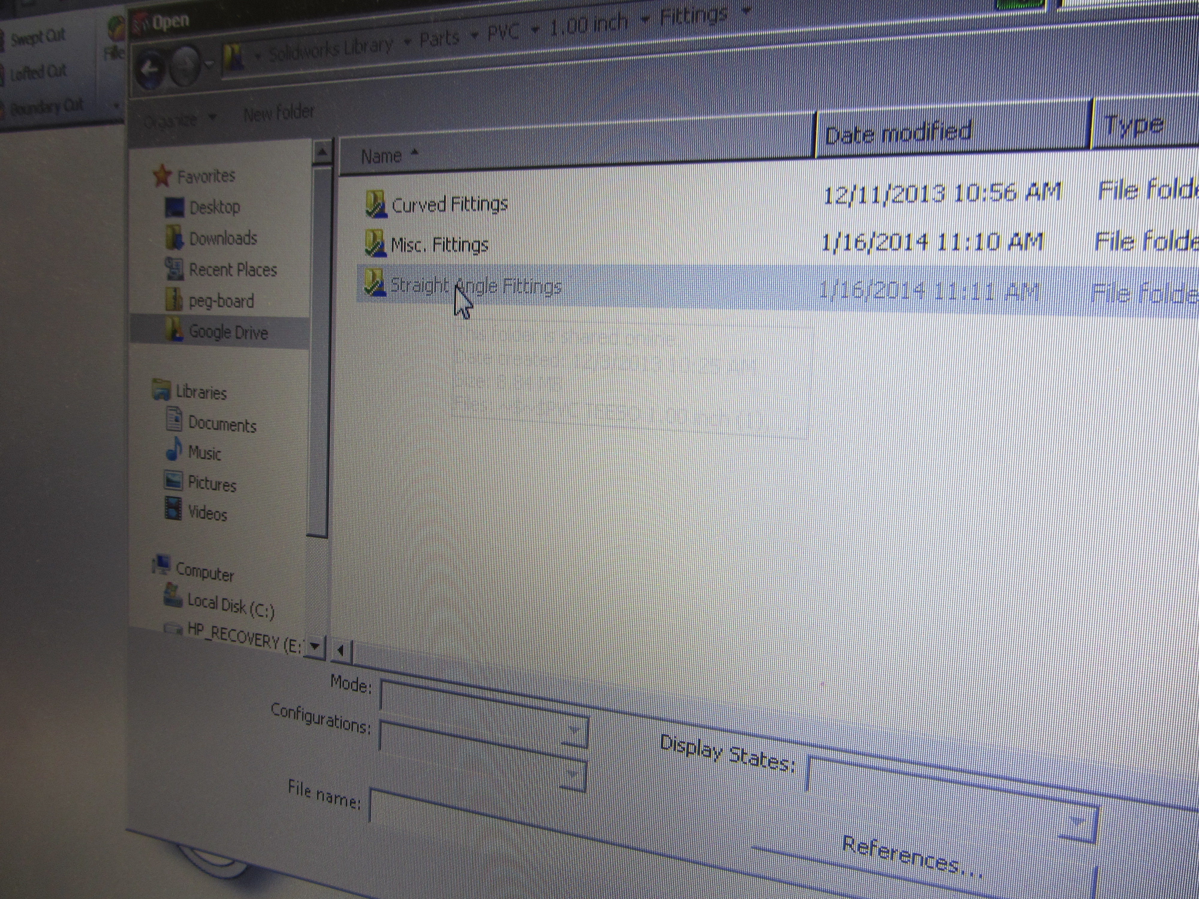
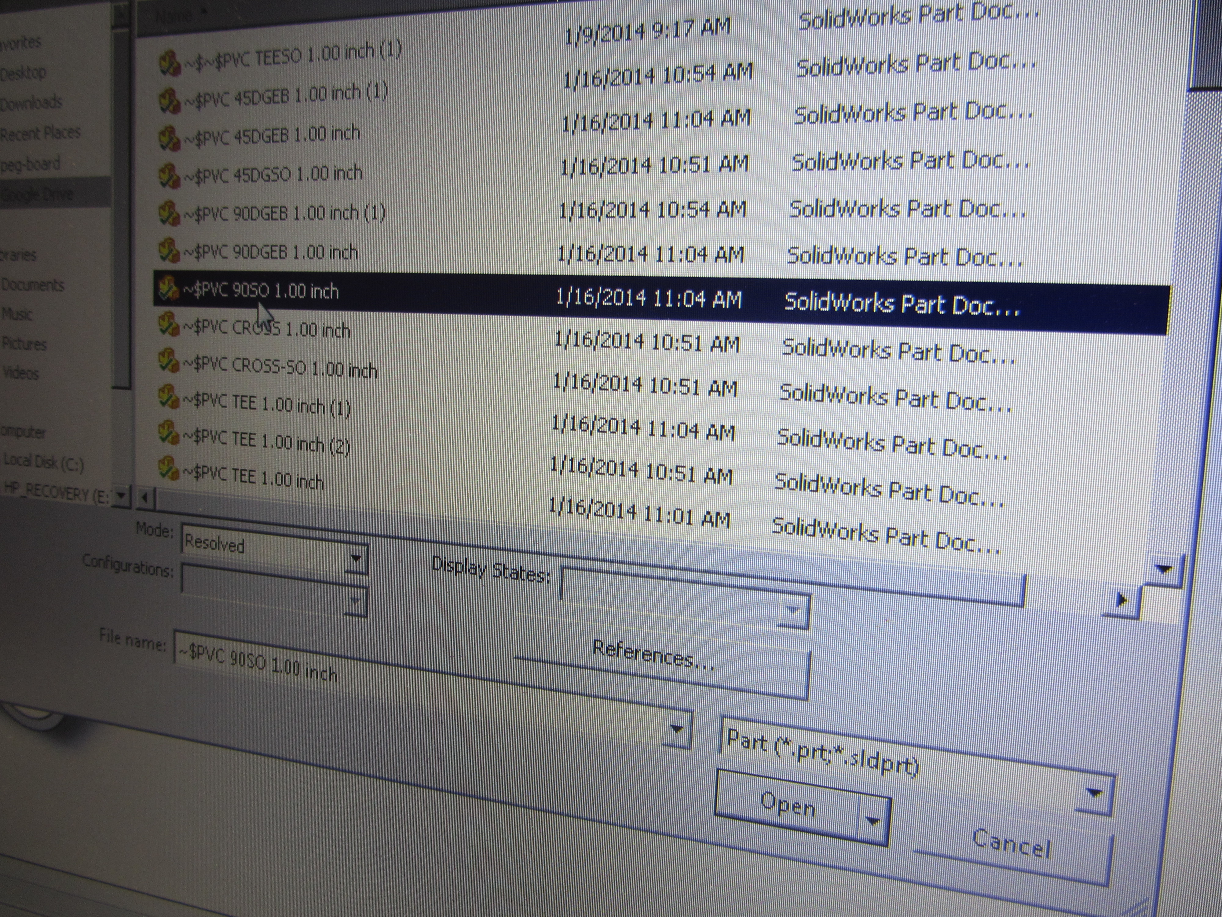
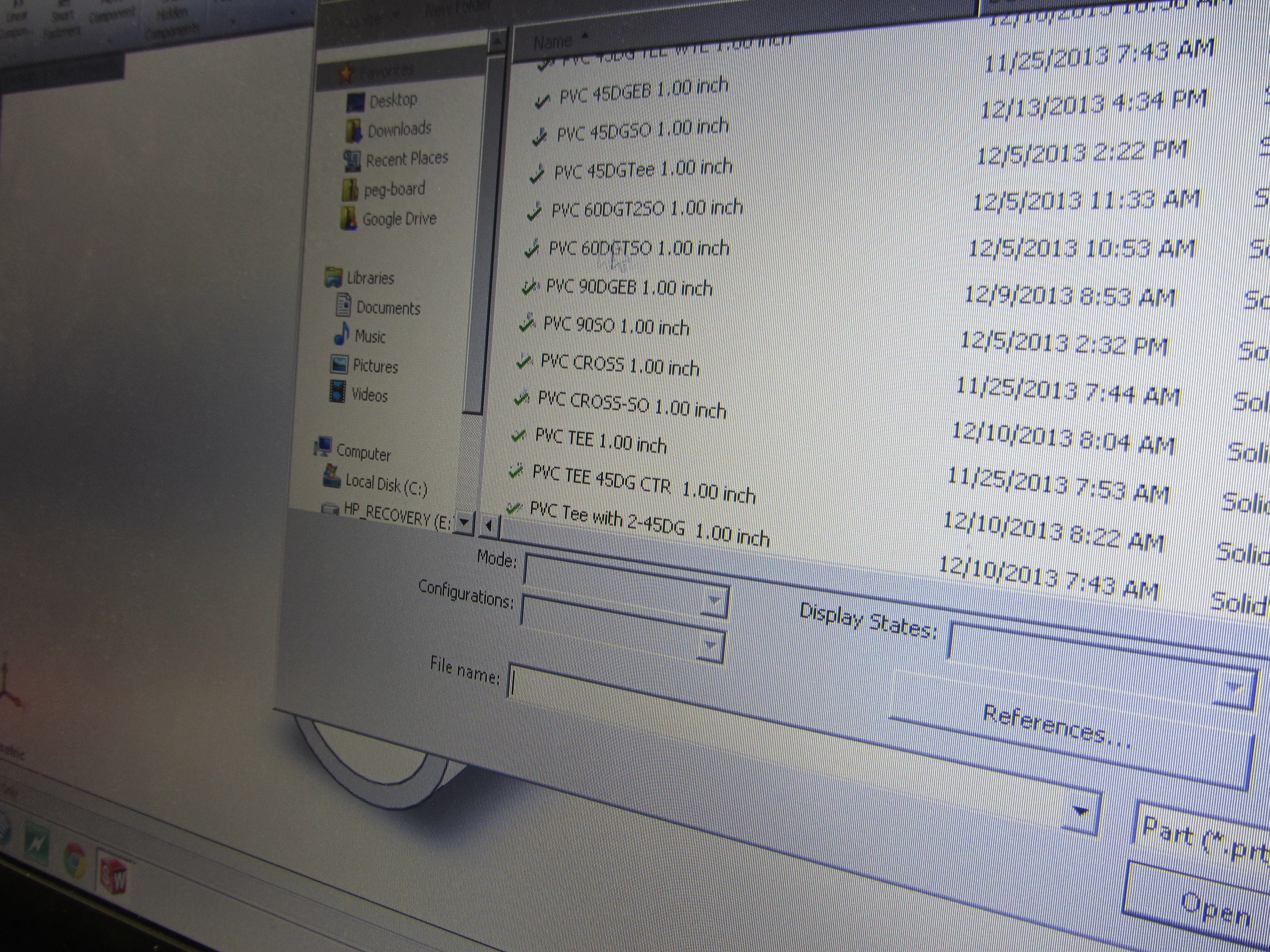
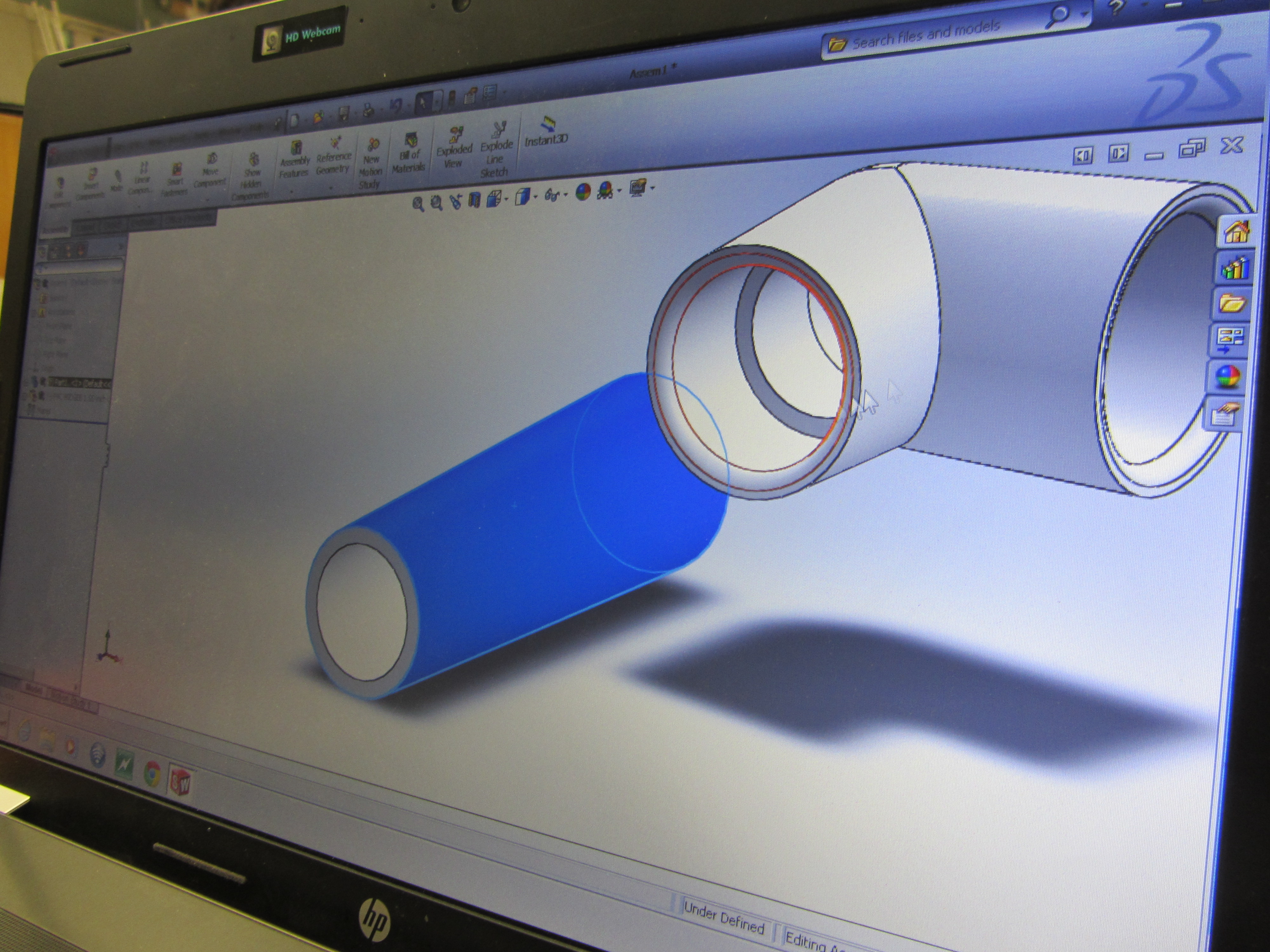
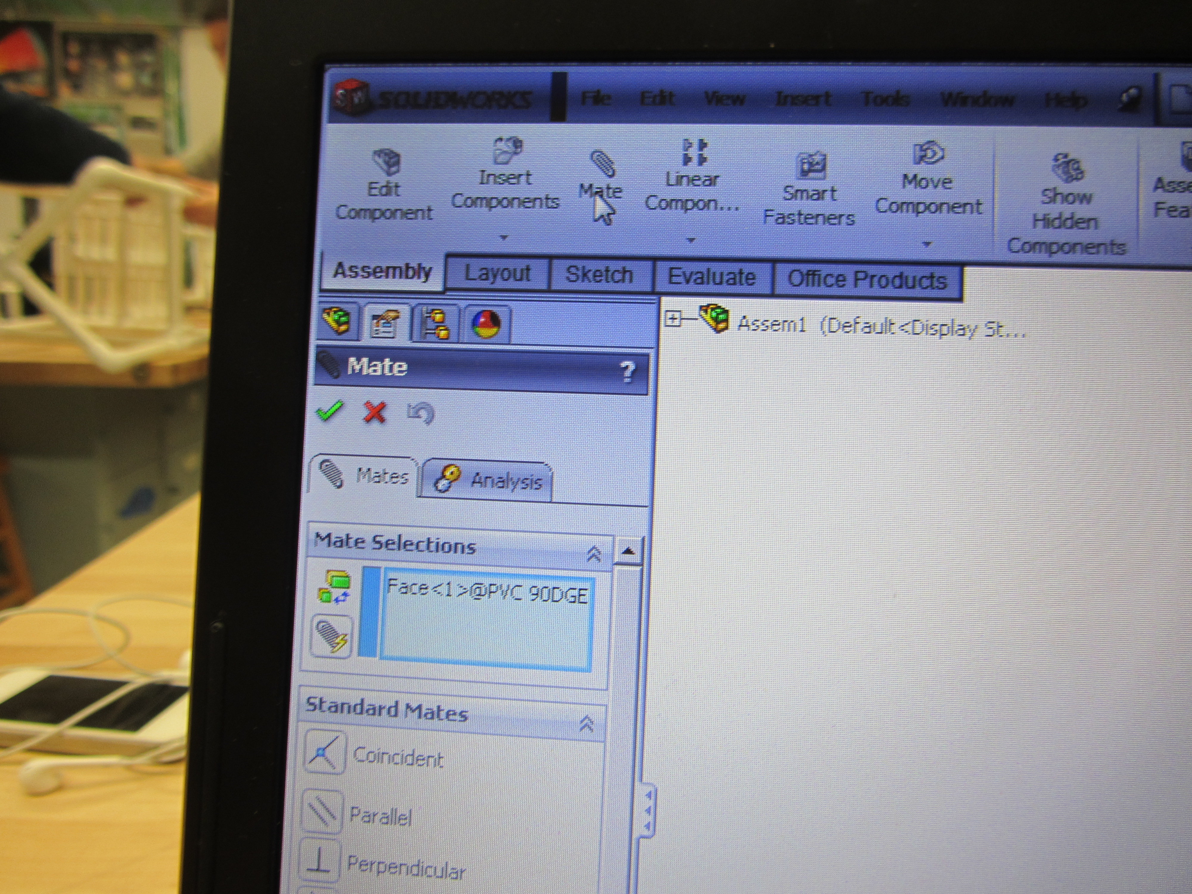
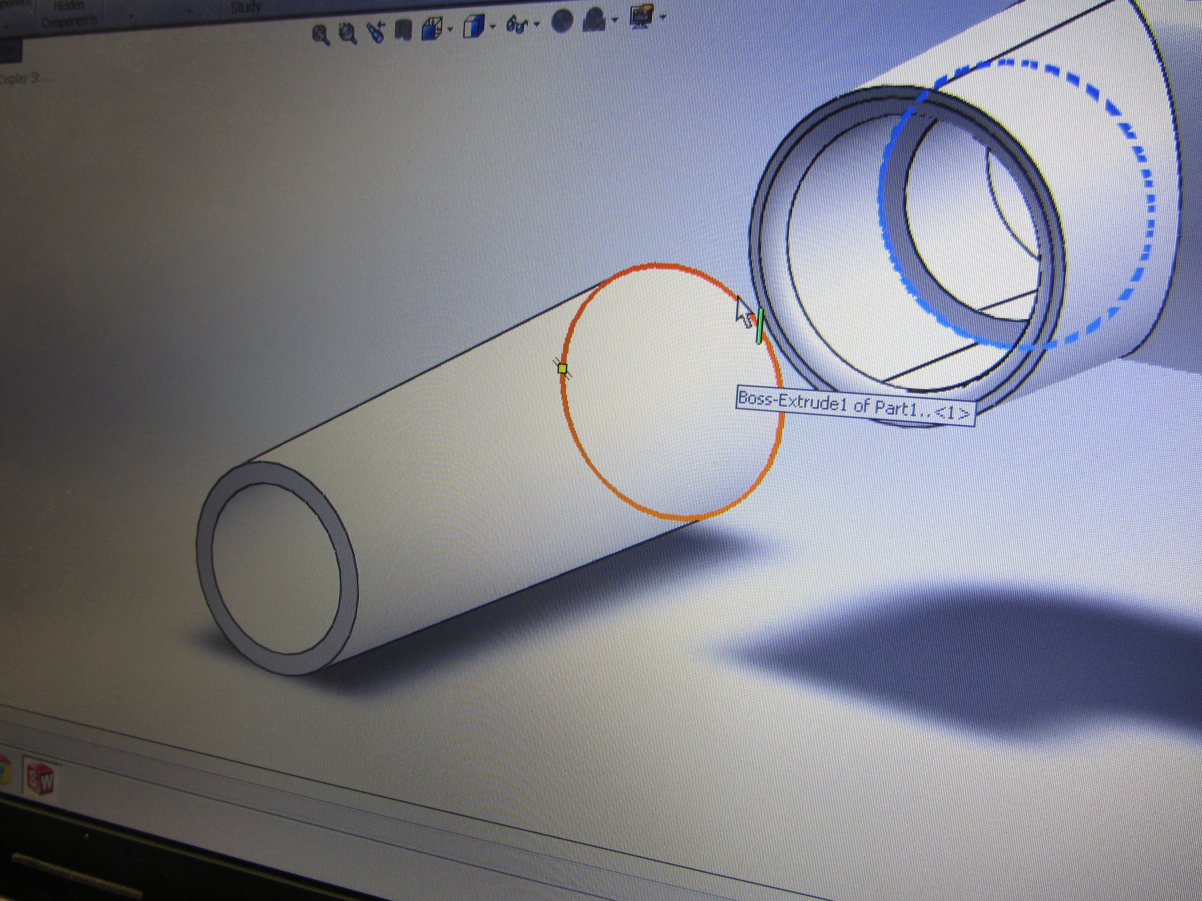
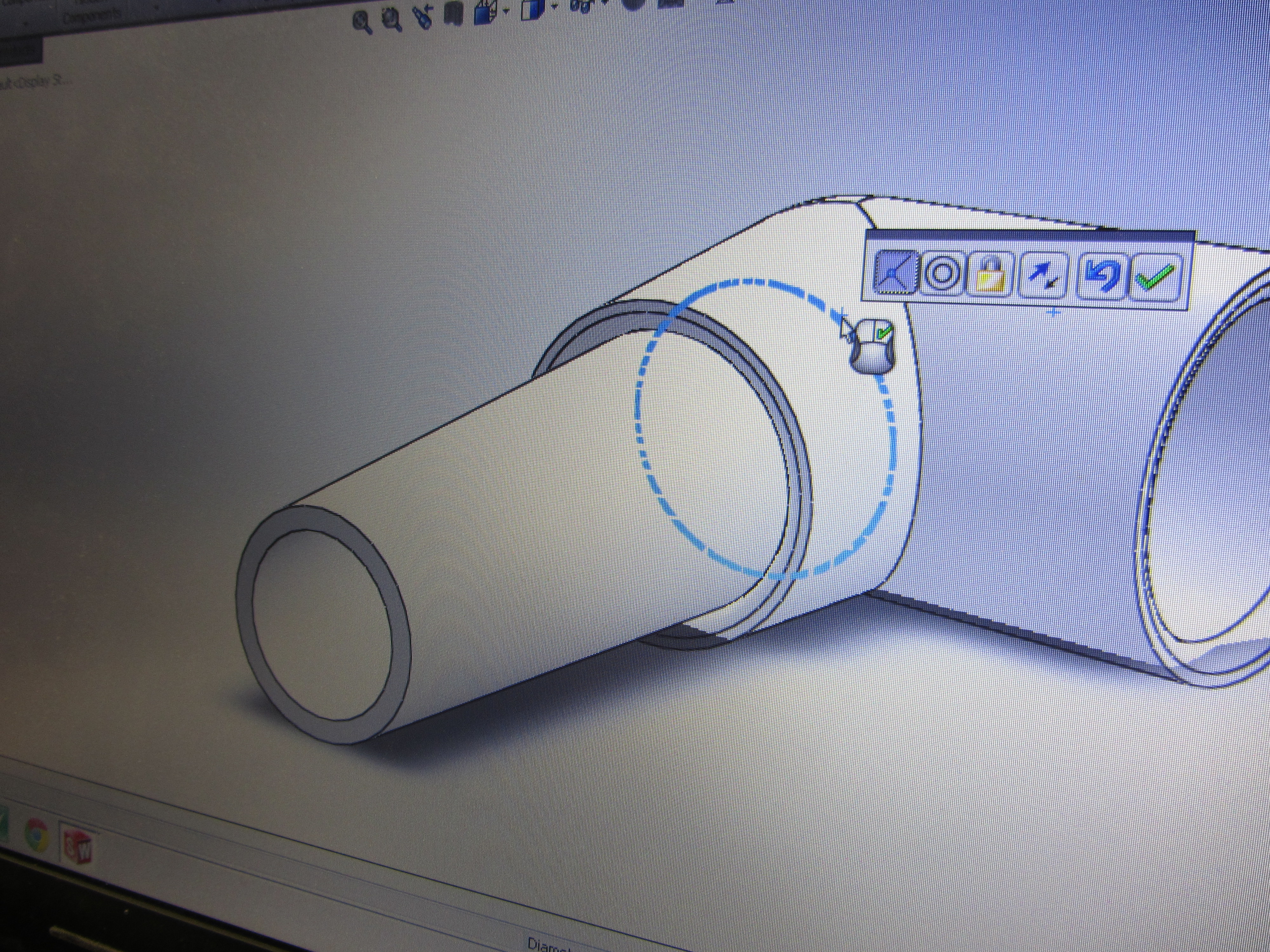
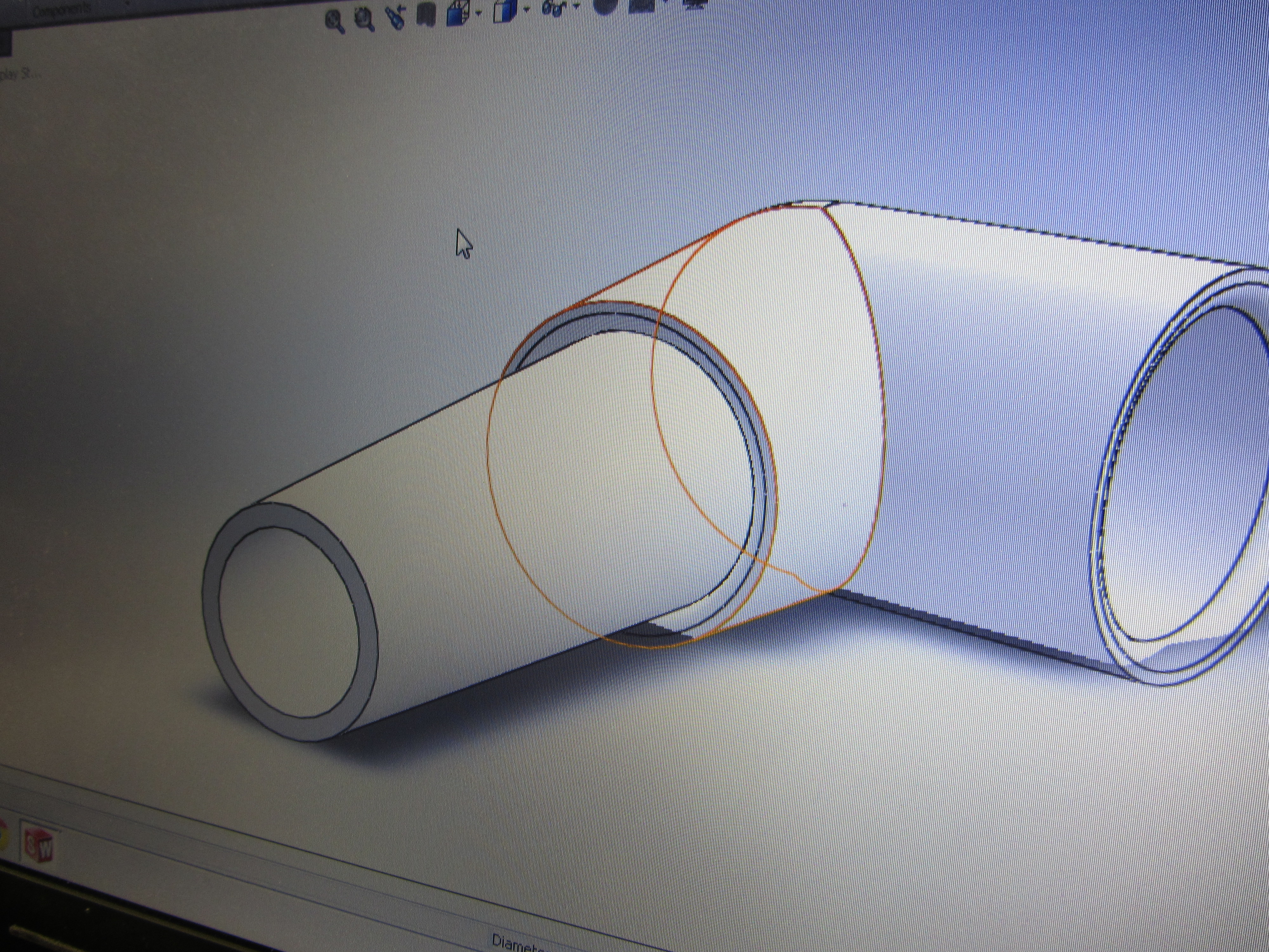
To make a PVC pipe go into a connector PVC piece.
Now that the PVC hollow cylinder pipe is on the sketch then you have to insert a PVC pipe fitting. Depending on what angle you need for the PVC pipe the fitting will change. To get to the fitting in solidworks you have:
-to click on insert components
-click on browse then click on google drive
-click on solidworks library then click on parts
-click on PVC then click on one inch
-click on the fittings folder then click on which ever fitting you need
On the solidworks sketch you'll now see two pieces that you want to be together.
First, go to the PVC piece and click on the outter edge of one of the faces of the hollow cylinder and that portion will be lit up
-then click outter edge of PVC pipe
-click on outter most inner edge of the PVC fitting
Solidworks Part III: Sub Assemblies
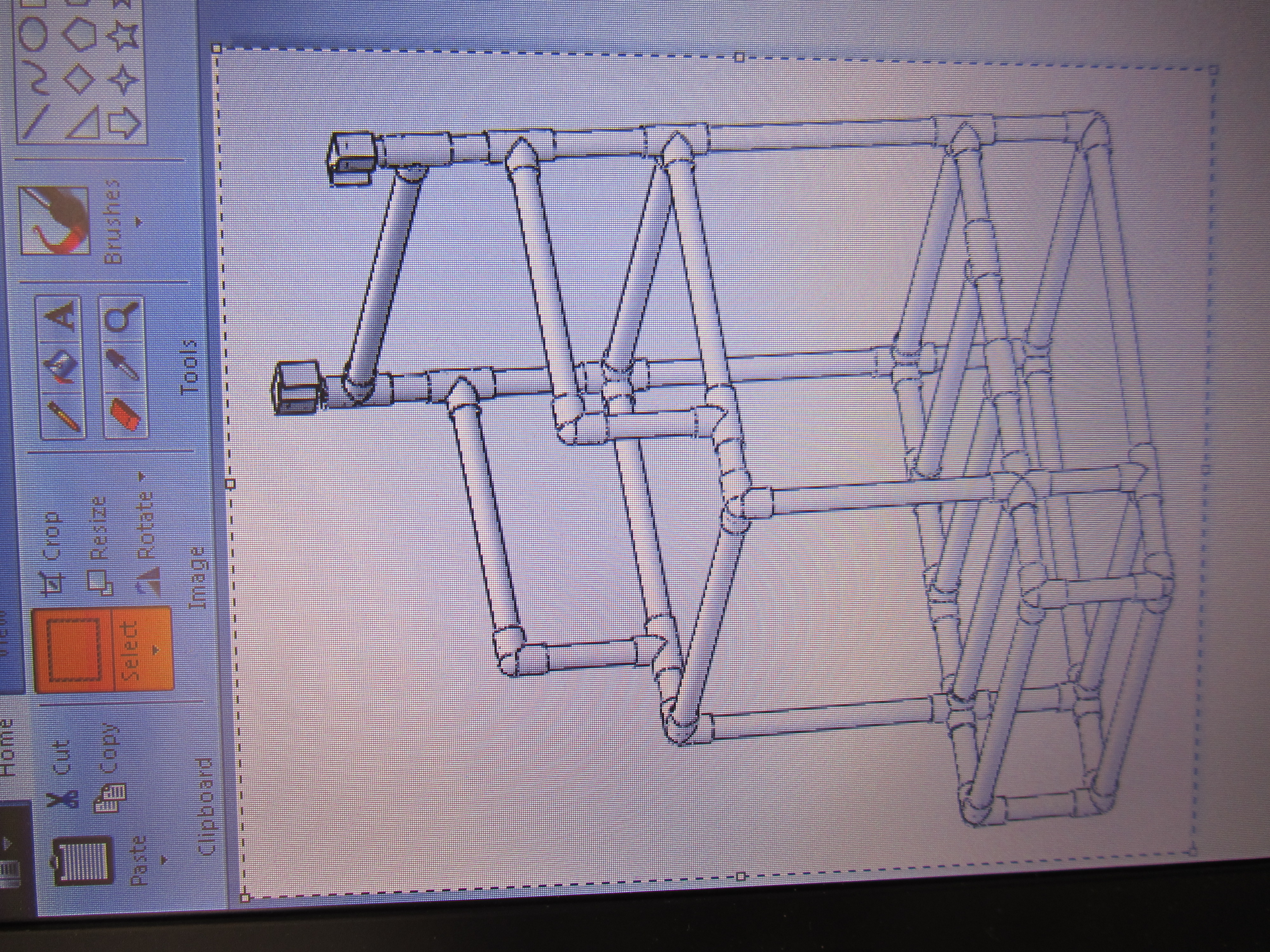
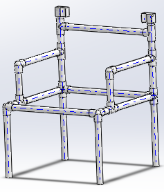
For the chair with the curved back there were 2 sub assemblies
one sub assembly was the bottom structure with the foot rest.
the second one was the square structure that sits on top of the bottom structure with the foot rest. The square structure also includes the arm rests.
The first and second sub assemblies fit together where the square structure meets with the bottom structure.
The last sub assembly is the curved back piece that is lined with pipes so there is not an open gap. The curved back piece gets connected to the second sub assembly on the back of the chair.
These 3 sub assemblies create one complete chair.
How to Physically Put Chair Together
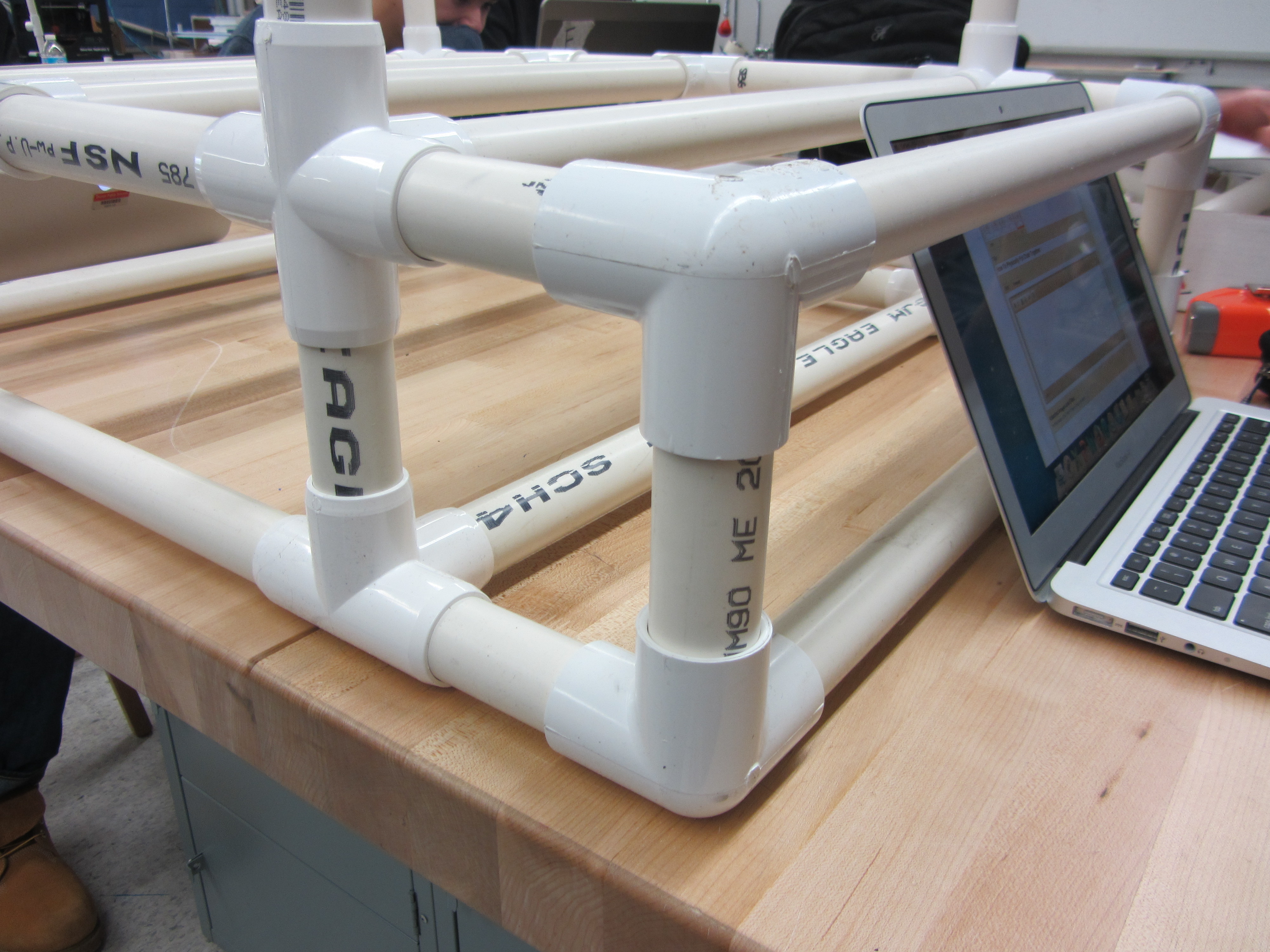
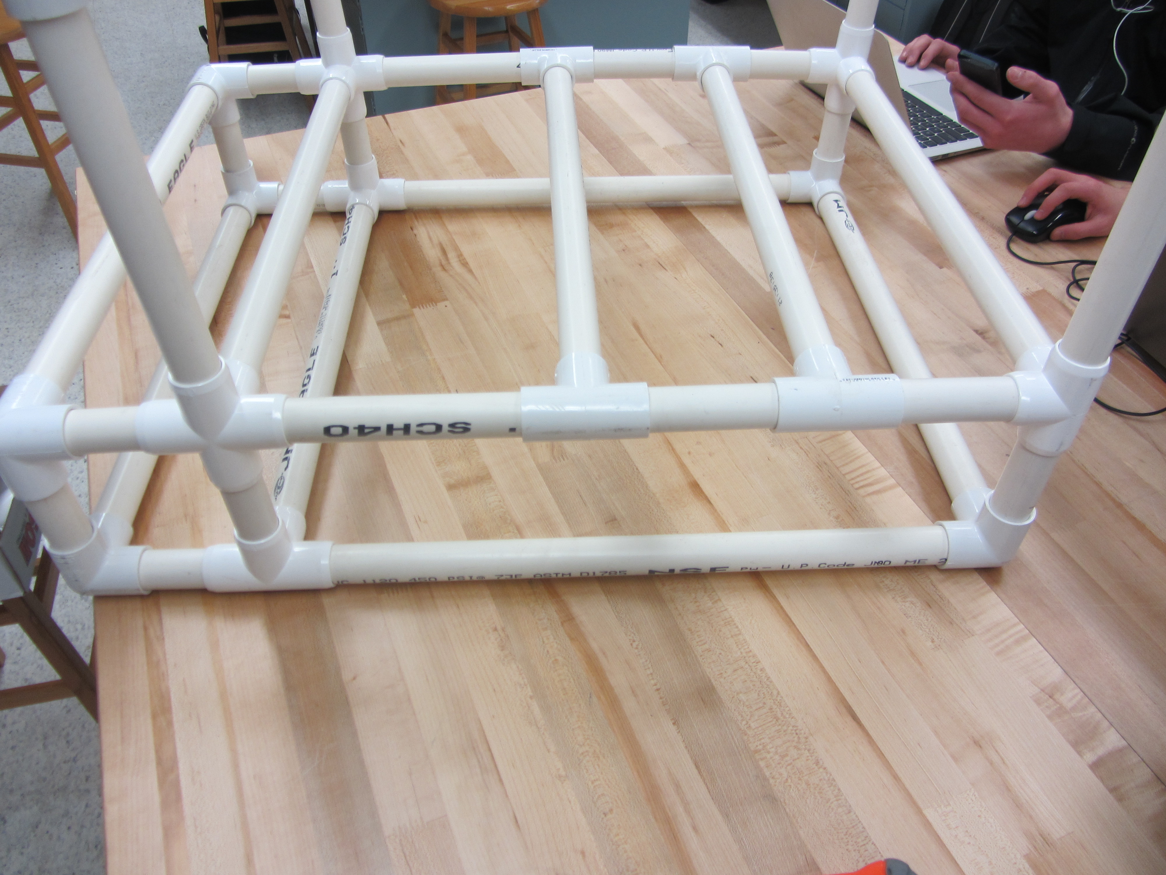
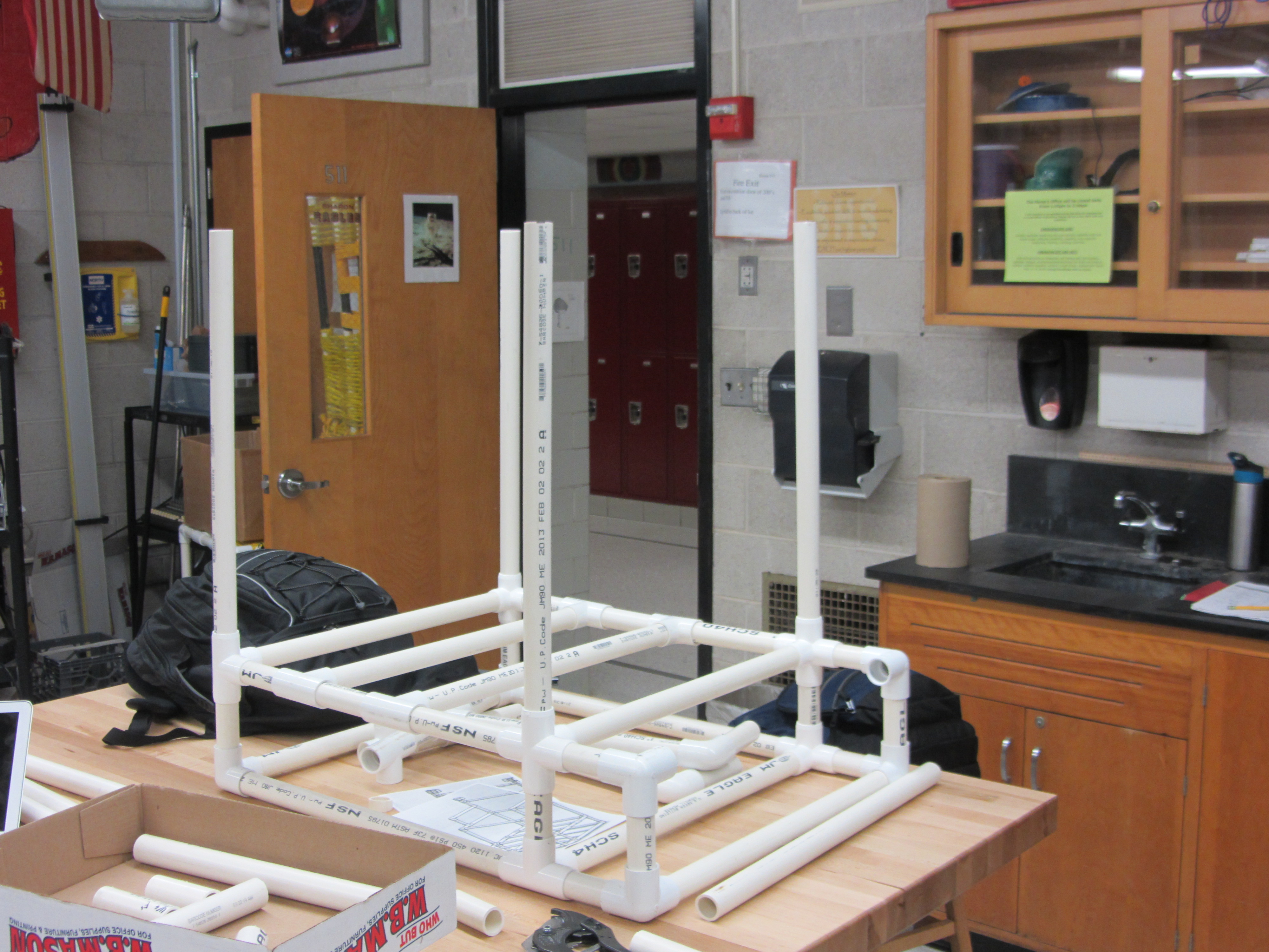
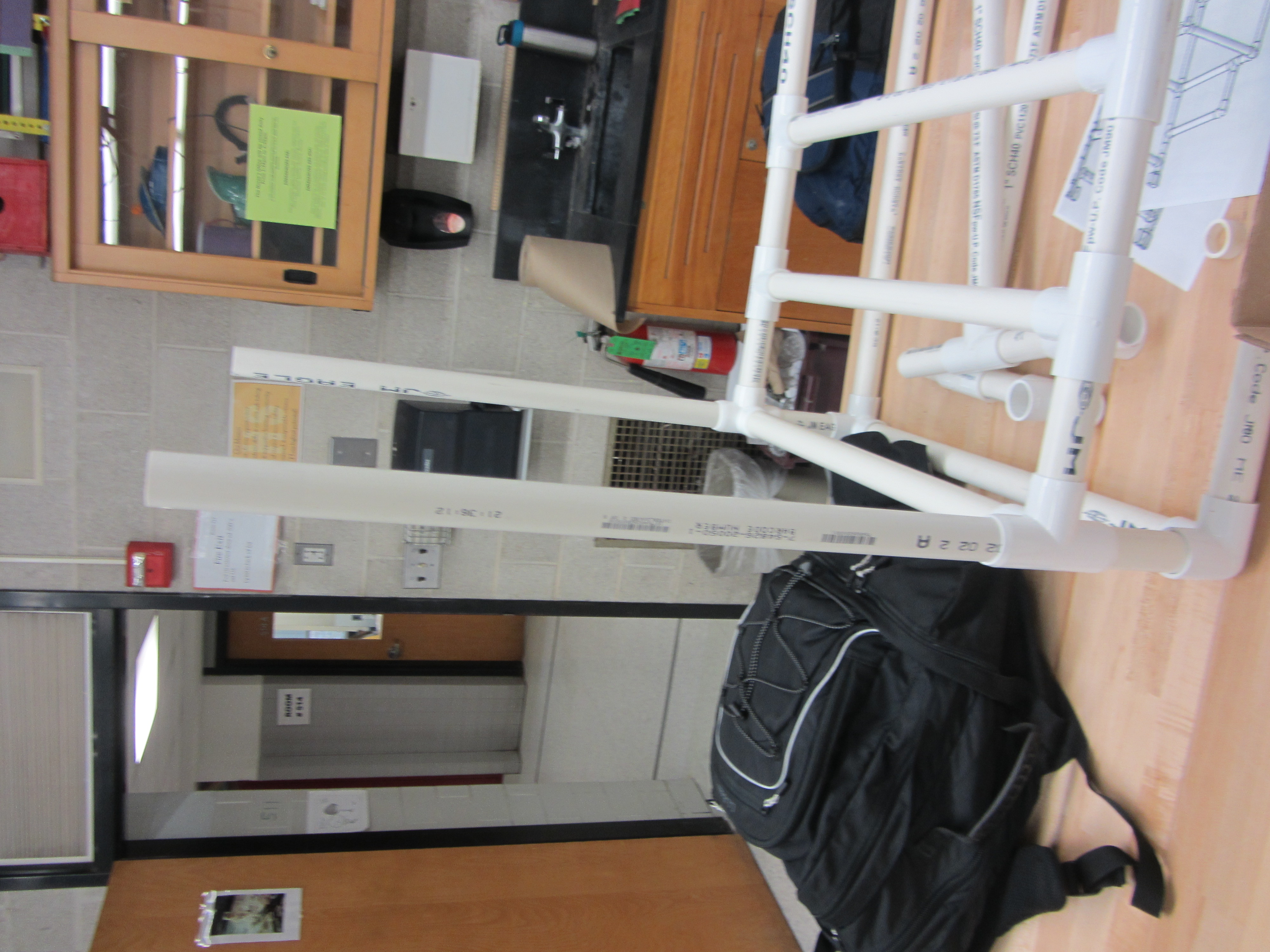
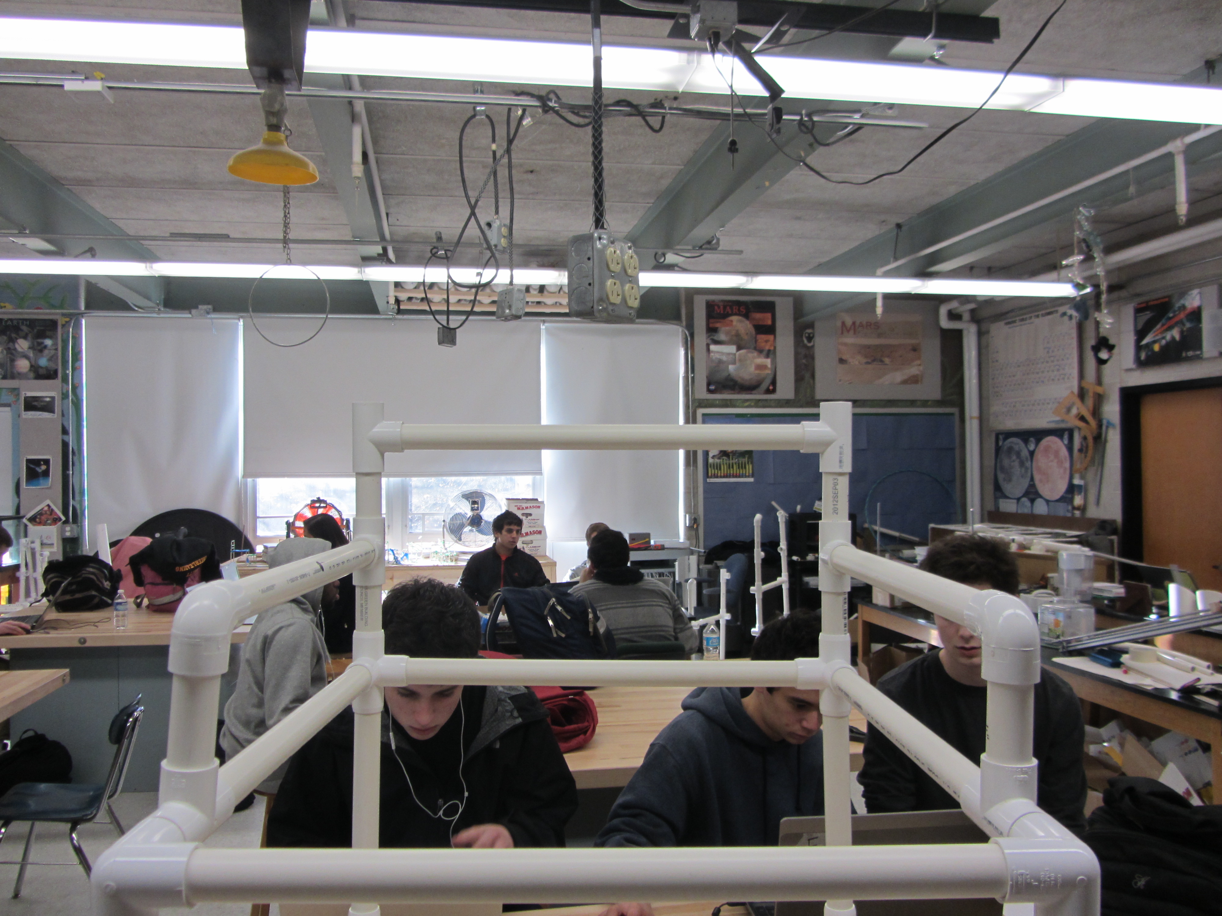
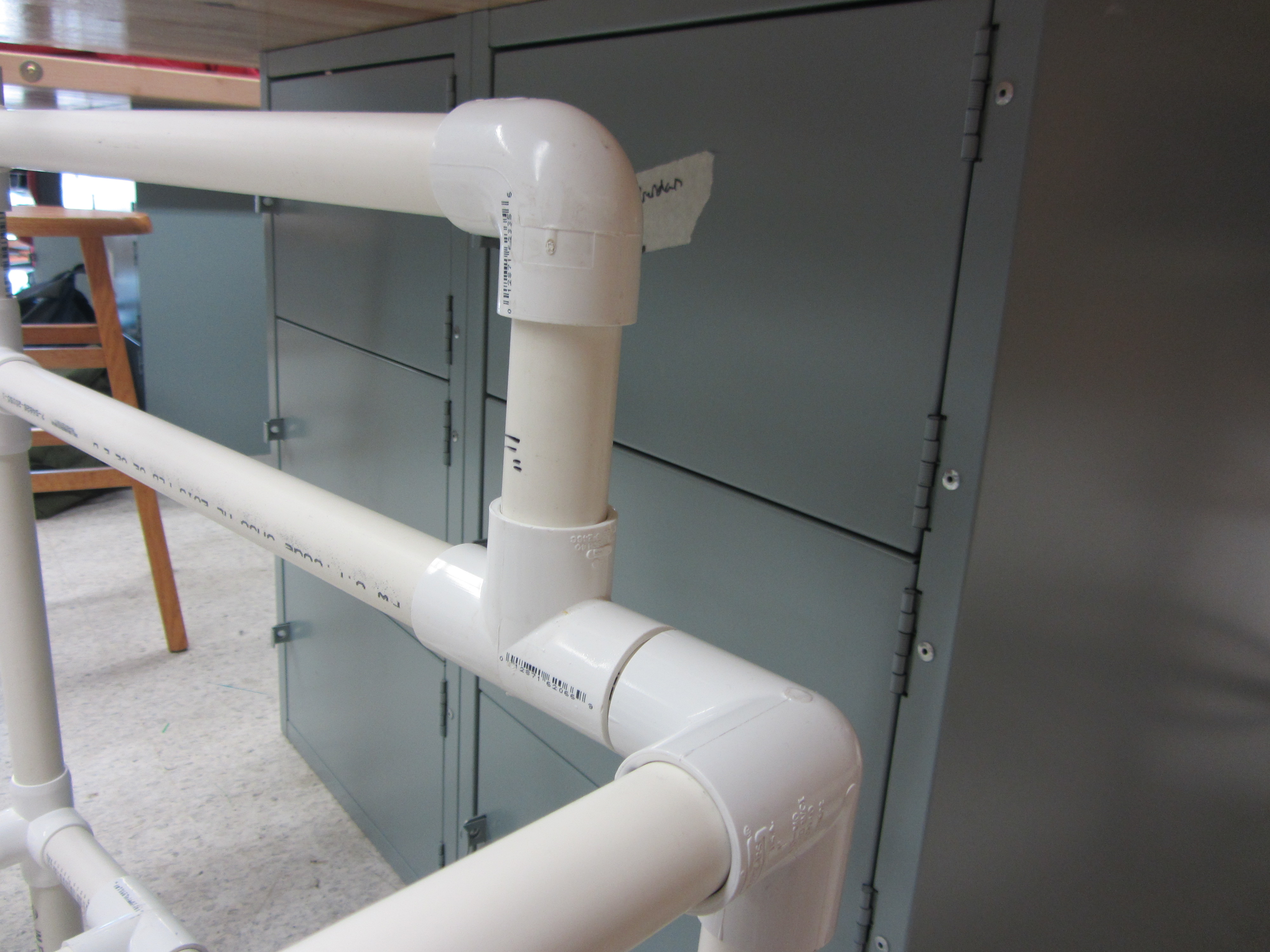
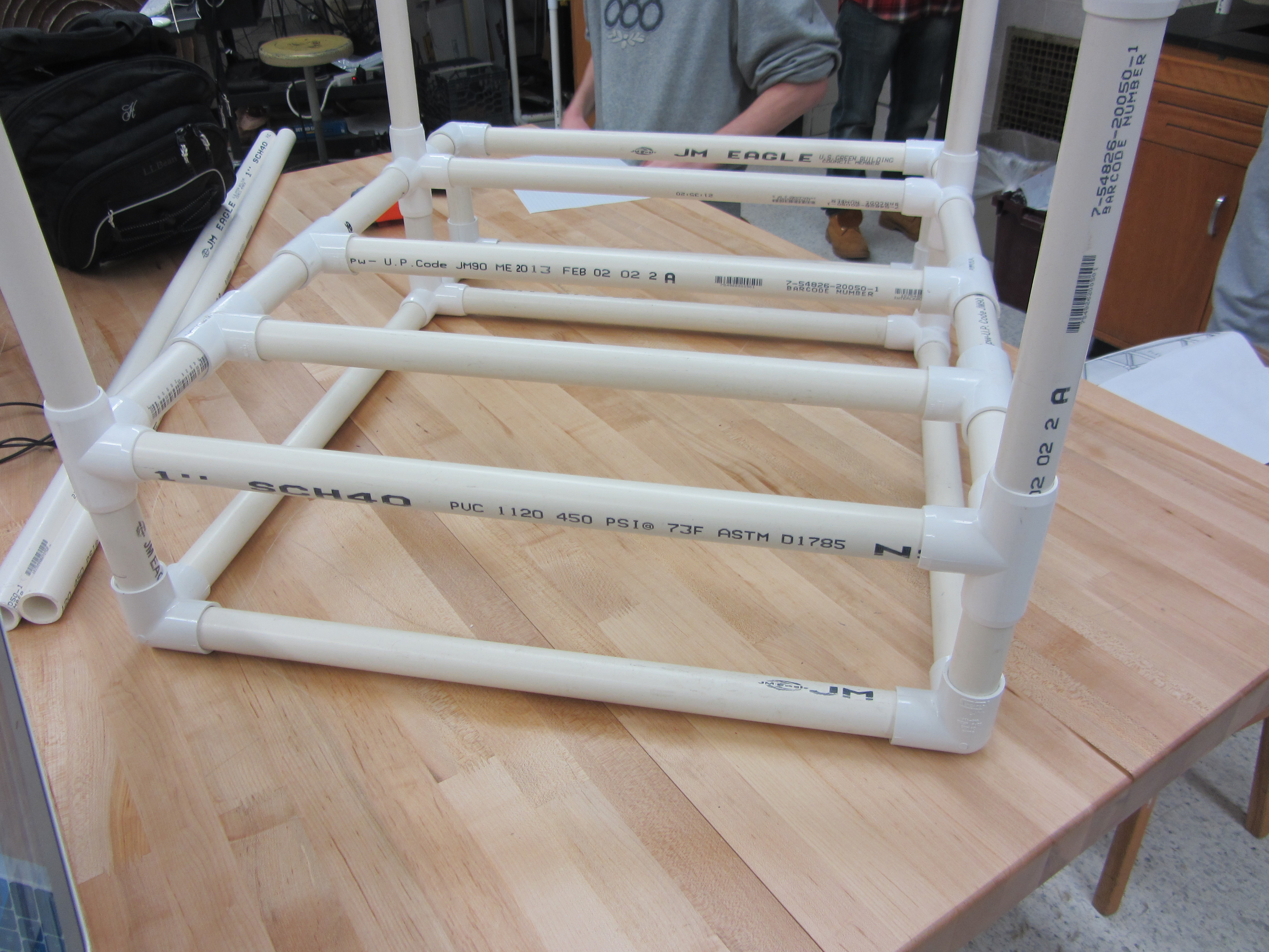
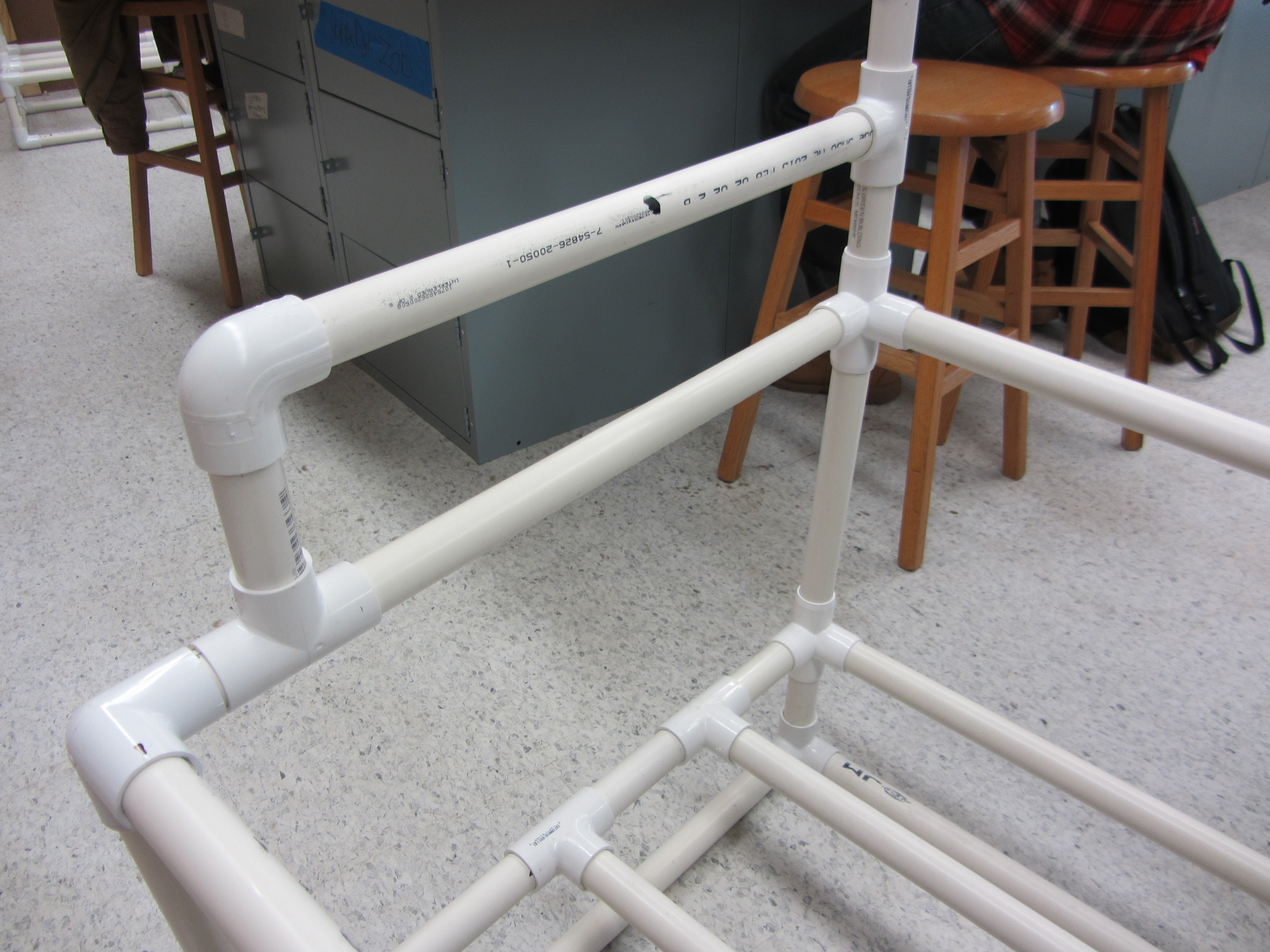
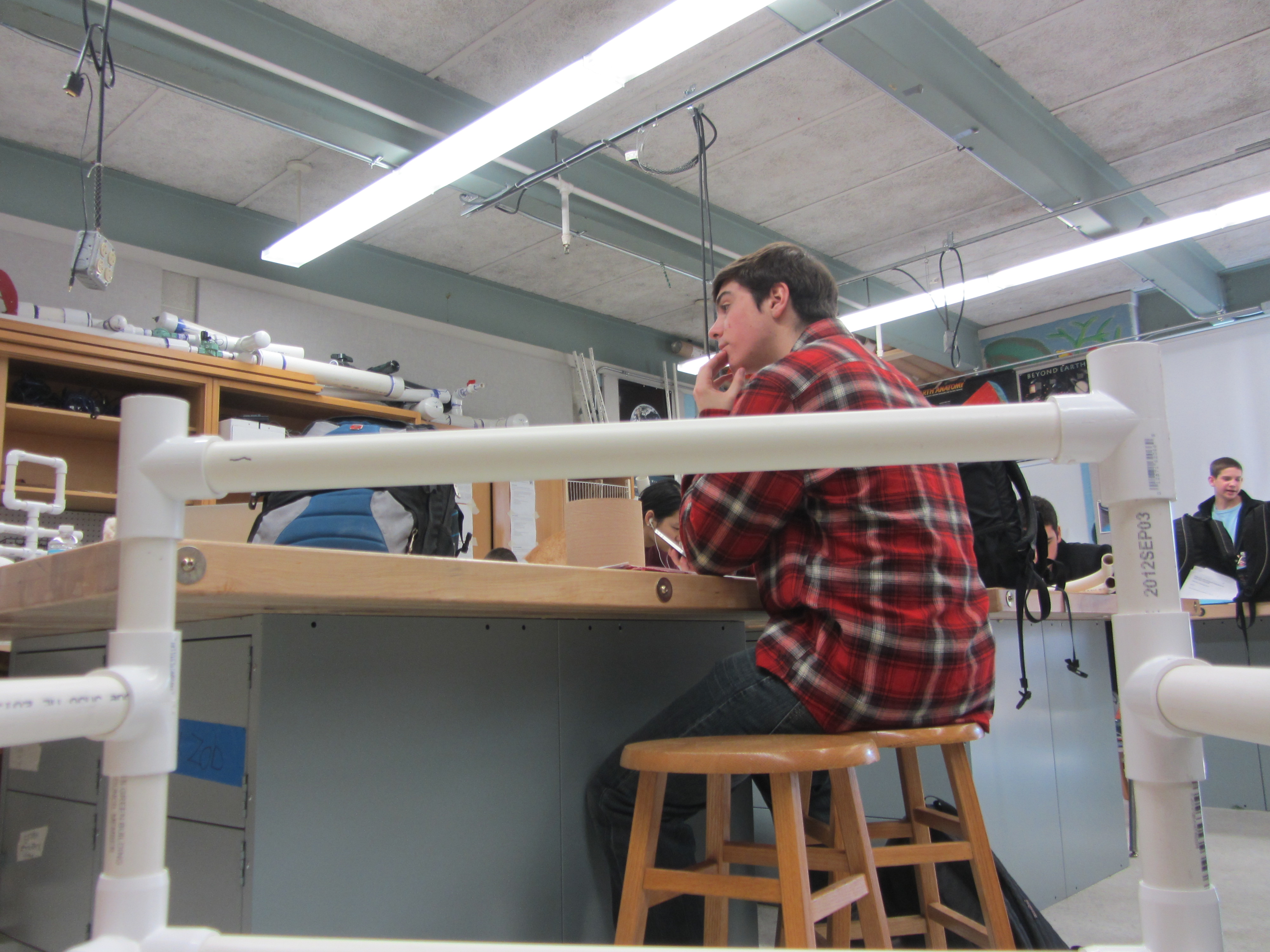
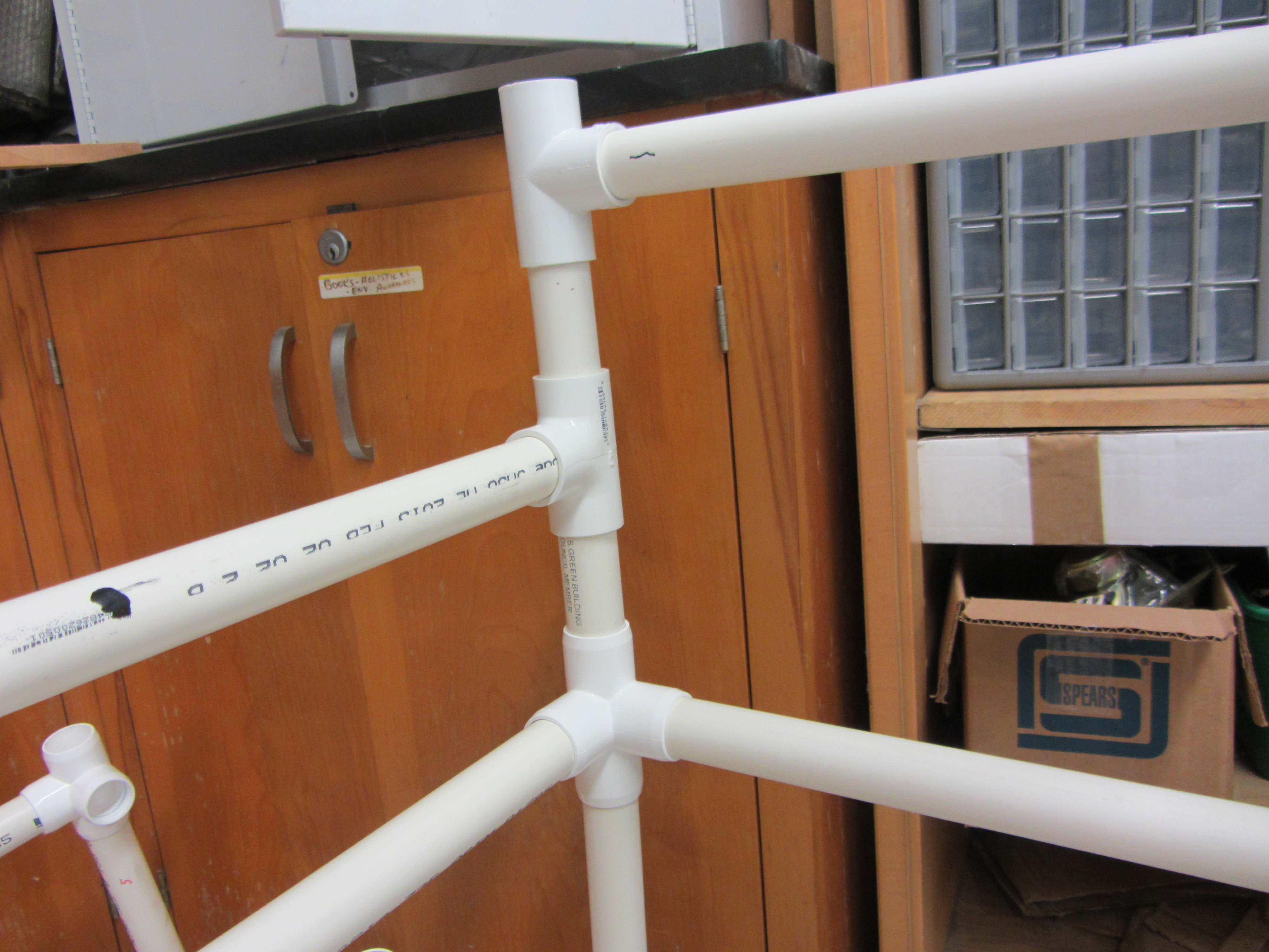
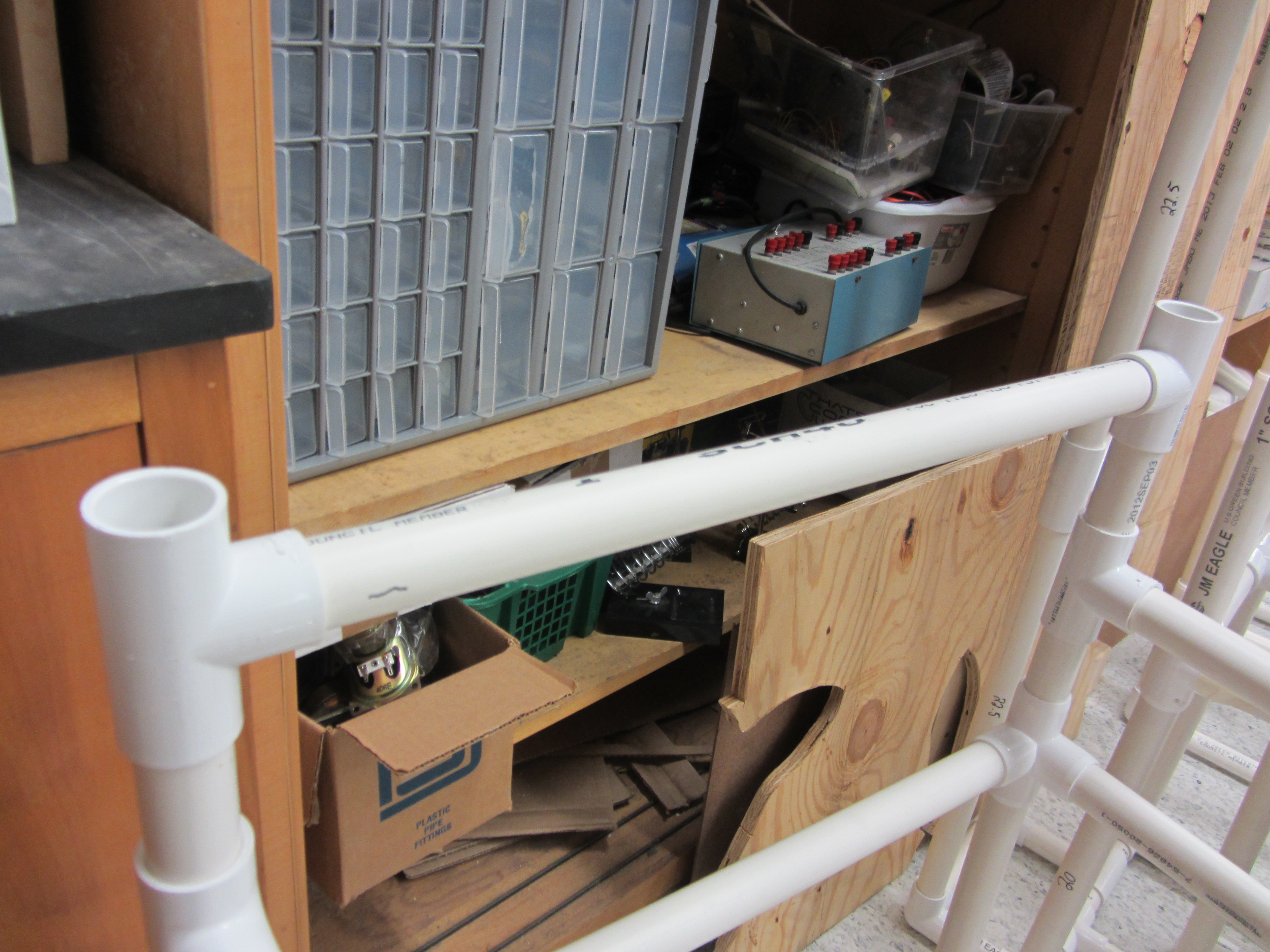
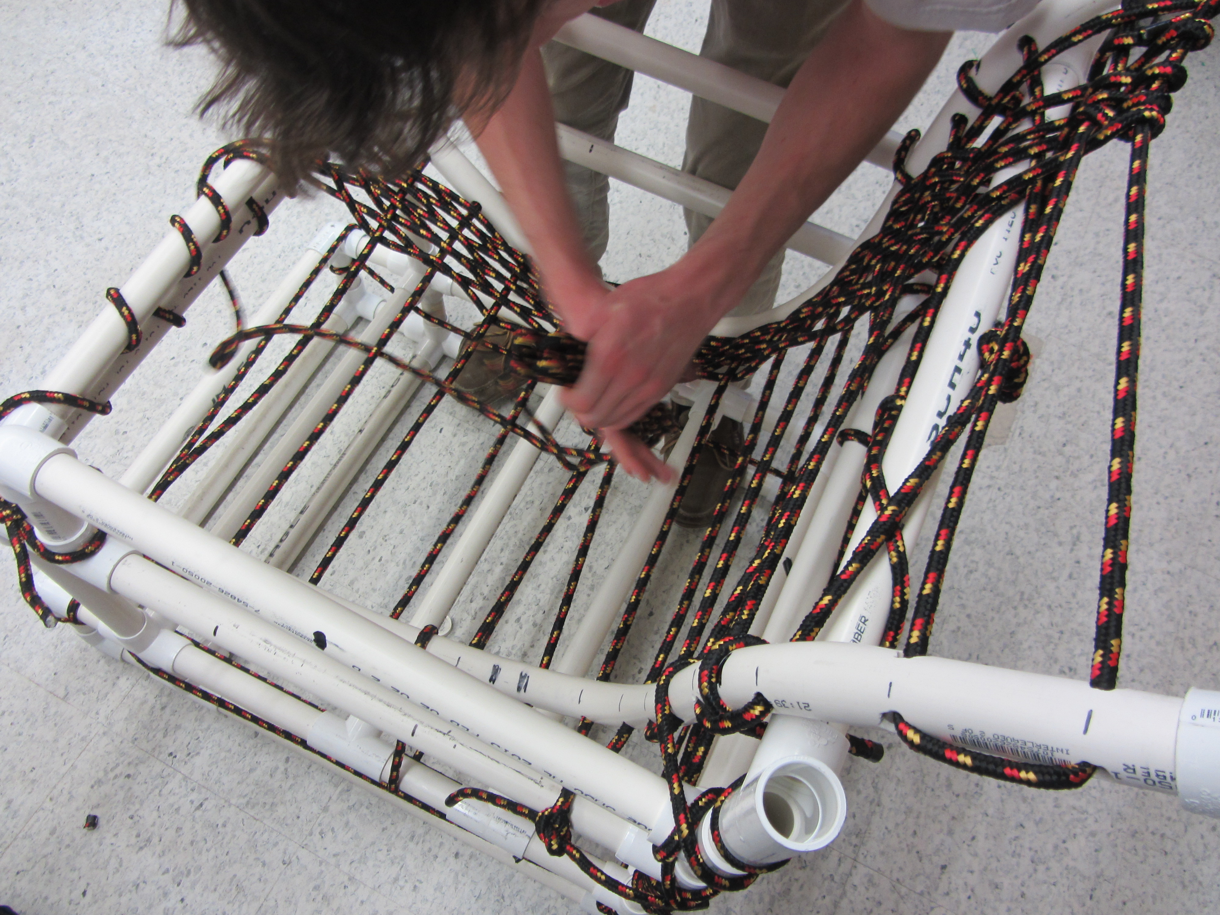
The first sub assembly was the bottom structure with the foot rest. We started building the chair with square that connects to the bottom of the foot rest. The picture that shows the foot structure on corner has dimensions of two 4 inches on the top and bottom. The top 4 inch piece connects to a cross side outlet and 90 side outlet. The bottom 4 inch piece connects to a 90 side outlet and a T side outlet.
The rest of the bottom structure sub assembly is composed of 22 inch pieces and 8 inch pieces.
The first level of the structure is composed of 22 inches. The big square is the foundation of the whole chair. There are 5x22 inch pieces on the bottom. To complete the structure on the bottom there is the square structure that was previously explained.
The long pieces on the second level where there are 5 pieces of PVC pipe are all 22 inches in length. They get connected with T outlets, T side outlets, cross side outlets, and the 90 side outlets from the square in the footrest.
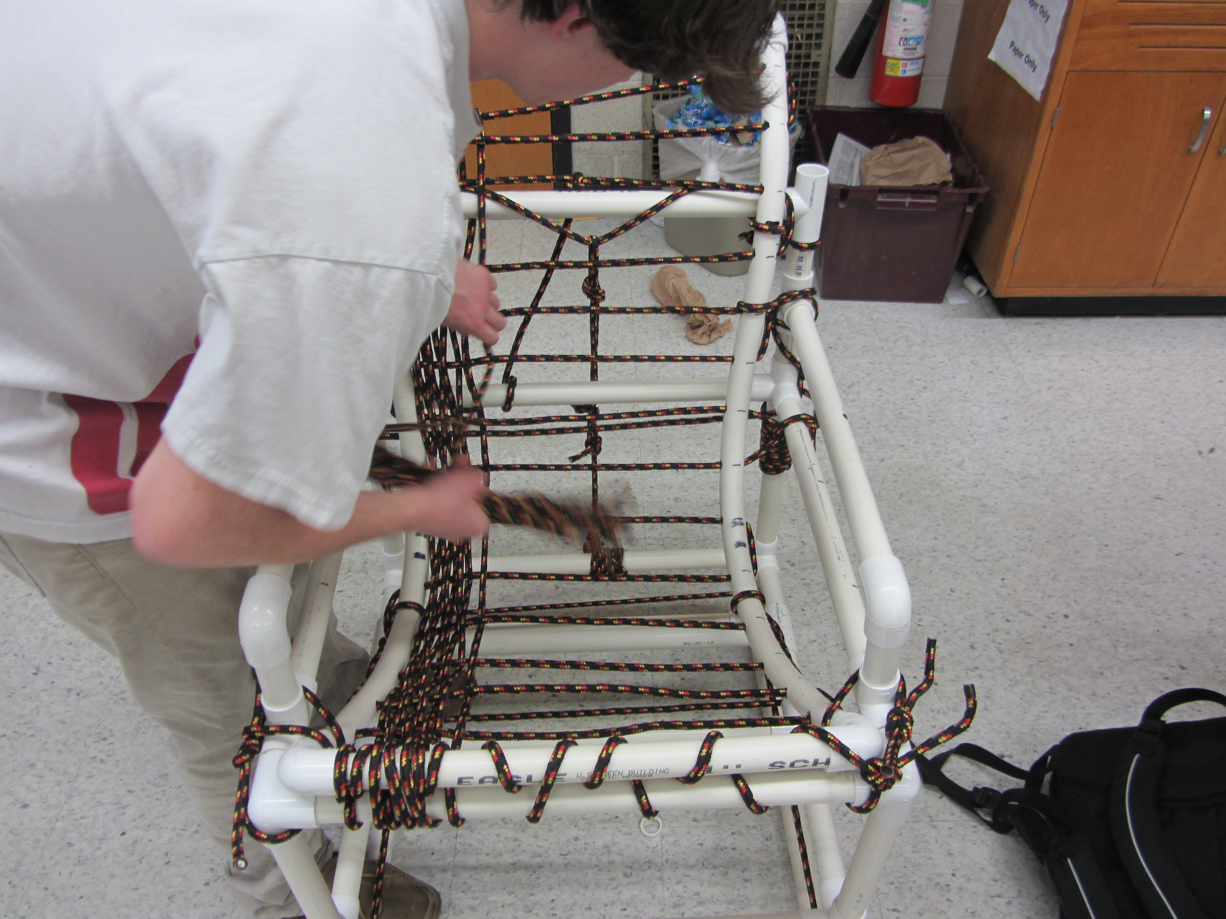
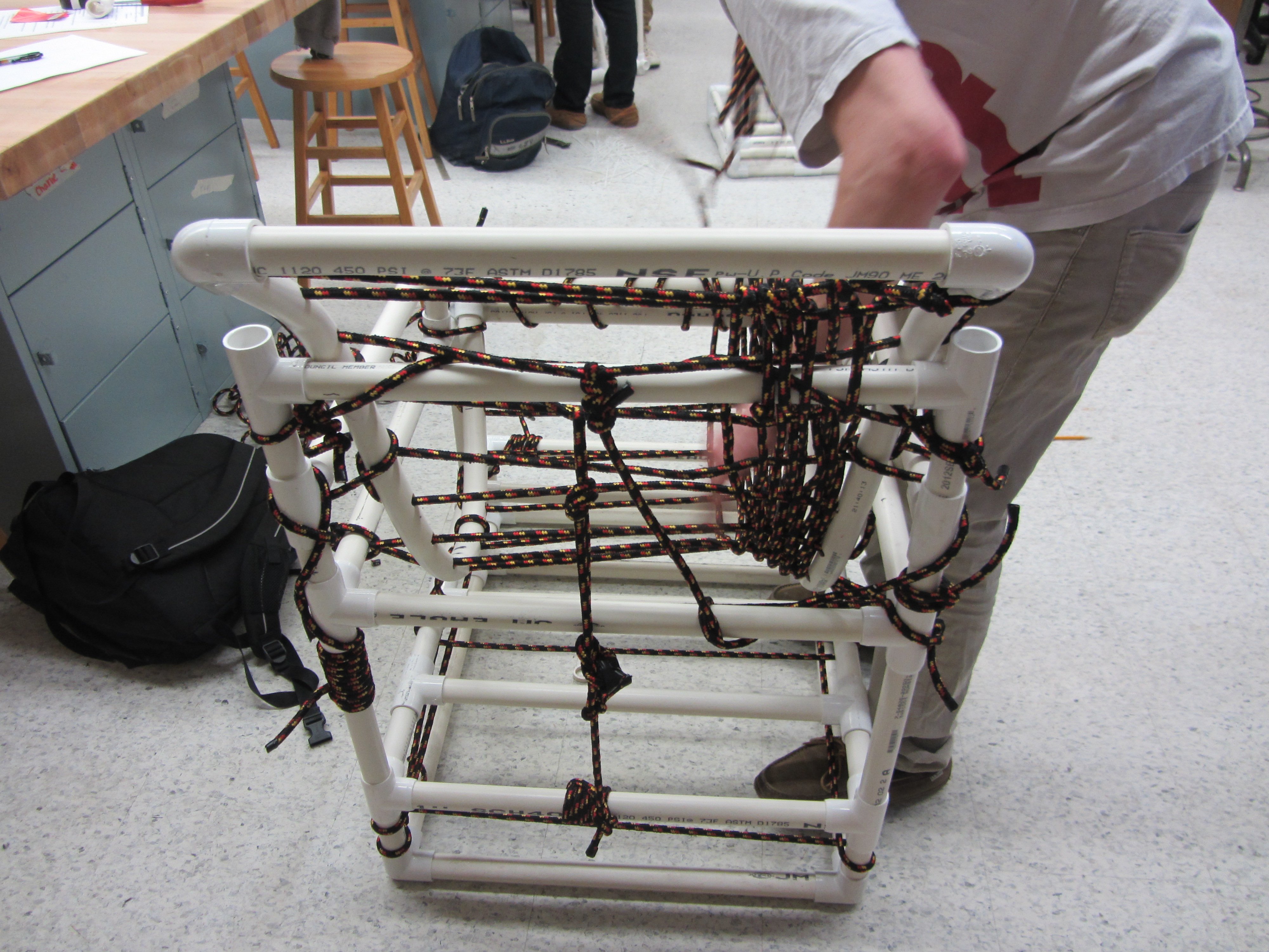
The second sub assembly is a lot simpler than the first. The pieces are made up of pieces that are a foot long in height. This may not seem like a lot but attaching these pieces to the first sub assembly that includes the bottom structure then it makes a total height of 21 inches. This 21 inches includes the pvc connector pieces. The 3rd and 4th picture illustrate this fully.
The 12 inch pieces connect to another square that sets up the opening for the seat. These 12 inch pieces get connected with T side outlets for the back 12 inch pieces and 90 side outlets for the front. See the 5th picture
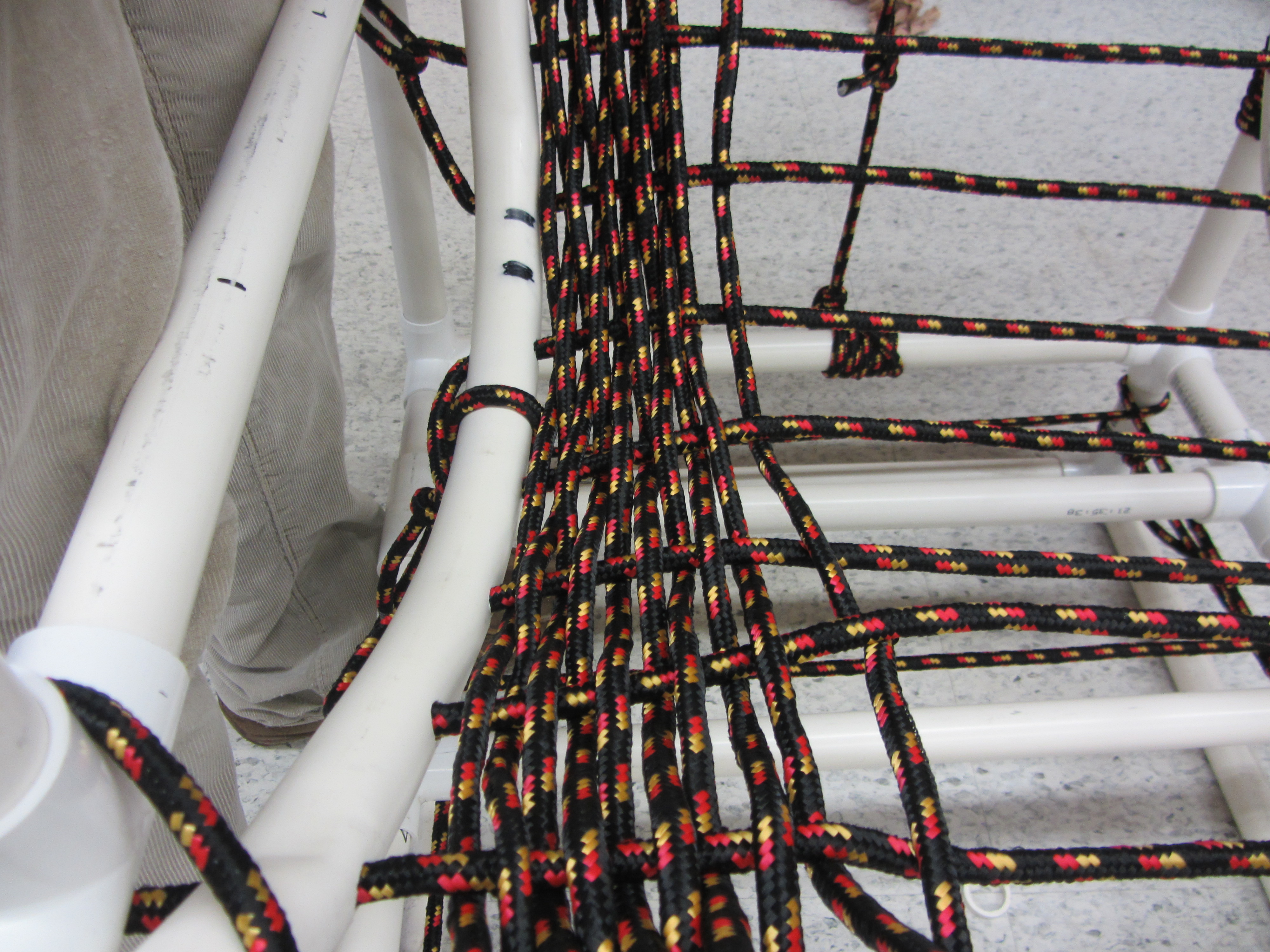
the rope shown is for the seat where the butt goes.
Since there are arm rests in the chair the square that connects to the 12 inch pieces has different measurements on the sides than it does for the front and back. The front and back pieces of the square are 22 inches. The side pieces of the square are 20.5 inches. These 20.5 inch pieces get connected with 2 inch pieces on the side. These 20 inch pieces get connected to the 2 inch pieces with T side outlets. The 2 inch pieces get connected to the 12 inch pieces with 90 side outlets. See the 6th picture.
The arm rests and pipe that'll let the back structure pipes rest on. The arm rests are 20.5 inches in length and have an elbow piece in the front and a T outlet in the back. The T outlet in the back is made up of 2x4.5 inch pieces. The top 4.5 inch piece has a T outlet that has a 22 inch piece jetting into it. This 22 supports the back structure bent PVC pieces. The final four pictures illustrate this.