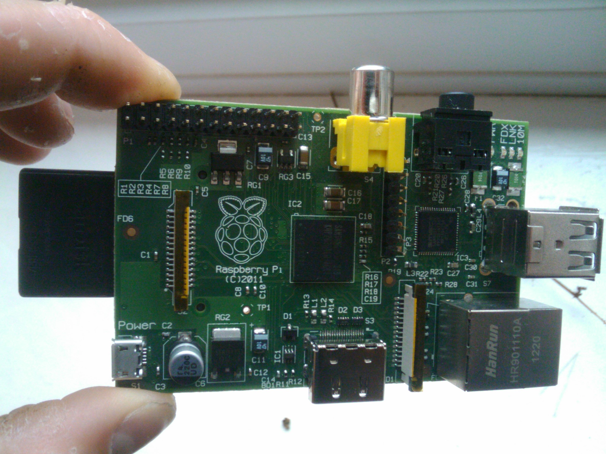
PICAXE Raspberry Pi ADC
by AntMan232 in Circuits > Raspberry Pi
56522 Views, 62 Favorites, 0 Comments
PICAXE Raspberry Pi ADC

In this instructable I will show you how to use a cheap PICAXE micro-controller as a multiple channel analogue to digital converter. We will be using I2C to access the PICAXE, which will be writing the adc values into the memory registers.
The Raspberry Pi does not have a built in ADC, which is unhelpful if you need to read any kind of analogue value, such as a variable resistor position or a light level etc. PICAXE is a line of cheap microcontrollers, designed to be easy to use for school children. This means they are easy to use, and you may have one lying in a draw. This instructable will show you how to use one as an ADC, but by writing values to it, you could conceivably use one as a port expander at the same time.
The Raspberry Pi does not have a built in ADC, which is unhelpful if you need to read any kind of analogue value, such as a variable resistor position or a light level etc. PICAXE is a line of cheap microcontrollers, designed to be easy to use for school children. This means they are easy to use, and you may have one lying in a draw. This instructable will show you how to use one as an ADC, but by writing values to it, you could conceivably use one as a port expander at the same time.
Set Up Pi

You will need to set up the pi for i2c for this instructable, which is explained in another of my instructables, here: Set up i2c . You need to get up to the point of running i2cdetect.
Circuit

WARNING: I will be connecting 5V logic to the Pi 3.3V pins. This has caused no damage, but I am not responsible if it breaks yours.
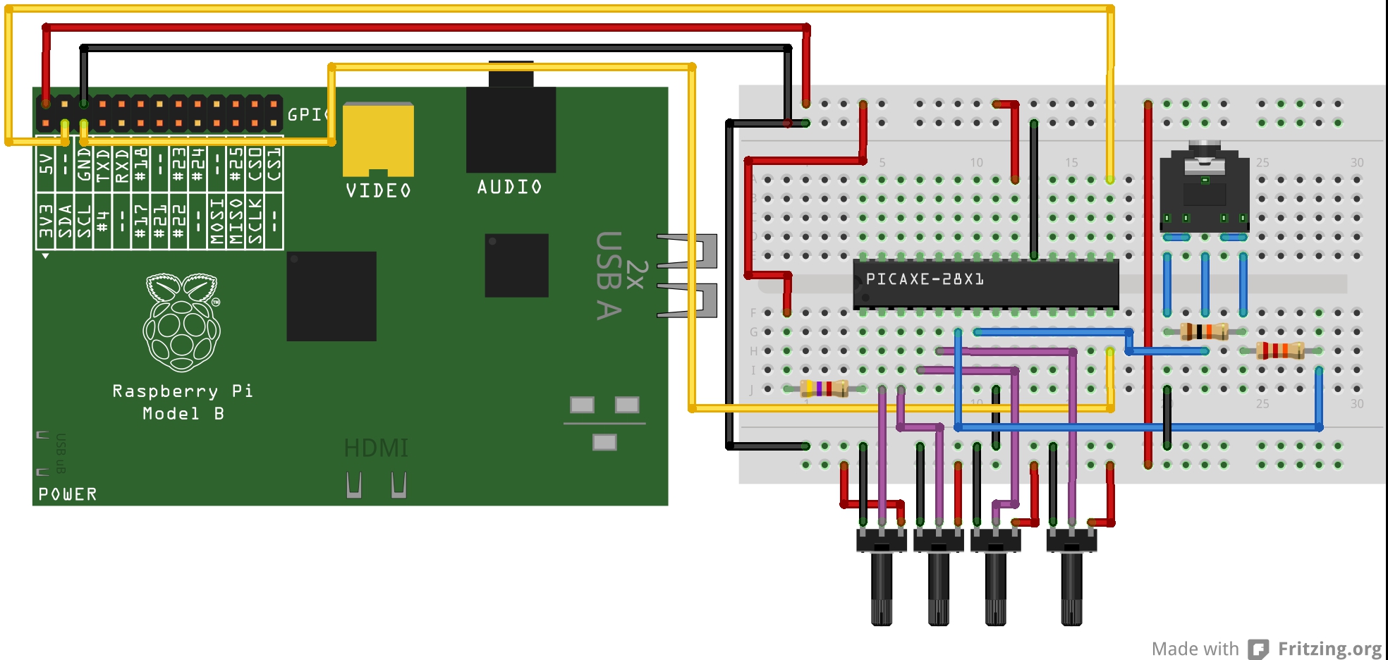
Only certain PICAXEs can act as an I2C slave, in this case I am using a 28X1. You need to build the basic operating circuit, as shown below.
Build the minimum operating circuit, of power and reset resistor, for the IC. Then, build the download socket and 2 resistors. This may not actually work on a breadboard, because the plug may not fit, so this might have to be assembled on veroboard. Finally, connect one end of each variable resistor to +, the other end to -, and connect the wiper to the ADC pins.
I have assumed some basic knowledge about PICAXEs, but if you have never used one before, I recommend reading PICAXE Manual 1 (just type it into google).
PICAXE Code

You will need to load the following code onto your PICAXE. In this case, it is set up to use all the ADC channels on the 28X1. It reads in the values, and writes them to the scratchpad, which can be accessed via I2C.
#no_data
#no_table
hi2csetup i2cslave, %00100000
main:
readadc 0,b1
readadc 1, b2
readadc 2, b3
readadc 3, b4
put 1, b1
put 2, b2
put 3, b3
put 4, b4
goto main
#no_data
#no_table
hi2csetup i2cslave, %00100000
main:
readadc 0,b1
readadc 1, b2
readadc 2, b3
readadc 3, b4
put 1, b1
put 2, b2
put 3, b3
put 4, b4
goto main
Raspberry Pi Code

The following program is a python script to access the PICAXE scratchpad over I2C, read the values, and print them on the screen. It also checks for the occasional bad read, and gets rid of them. Save the following code as X.py, and run it with sudo python X.py.
import smbus
import time
bus = smbus.SMBus(0)
address = 0x10
def read(register):
data = bus.read_byte_data(address, register)
return data
adc1 = 0
adc2 = 0
adc3 = 0
adc4 = 0
while True:
a1 = read(1)
a2 = read(2)
a3 = read(3)
a4 = read(4)
if a1 != 0:
adc1 = a1
if a2 != 0:
adc2 = a2
if a3 != 0:
adc3 = a3
if a4 != 0:
adc4 = a4
print adc1
print adc2
print adc3
print adc4
time.sleep(0.1)
Test!

You should now be ready to test it! Run your program on the pi with "sudo python X.py", and it should begin printing results rapidly down the screen! This code can be modified to use more/ fewer channels, such as those available on the 20M2. Thanks for reading!
pi@rpi ~ $ sudo python picaxe.py
0
170
52
184
75
170
52
184
75
170
52
184
75
170
52
184
75
...
pi@rpi ~ $ sudo python picaxe.py
0
170
52
184
75
170
52
184
75
170
52
184
75
170
52
184
75
...