P9S - Stool Made With CNC Router
by alepalan in Workshop > Woodworking
27562 Views, 228 Favorites, 0 Comments
P9S - Stool Made With CNC Router
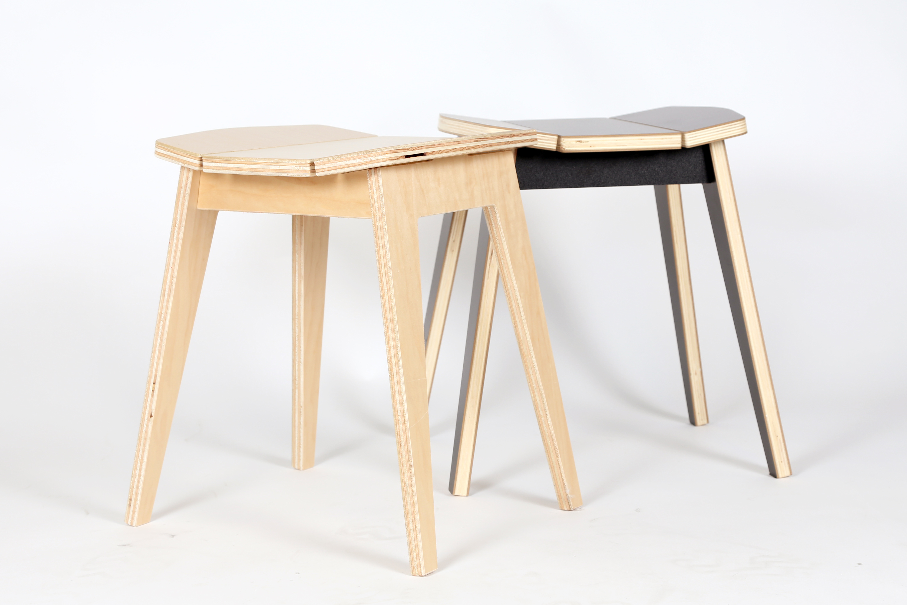
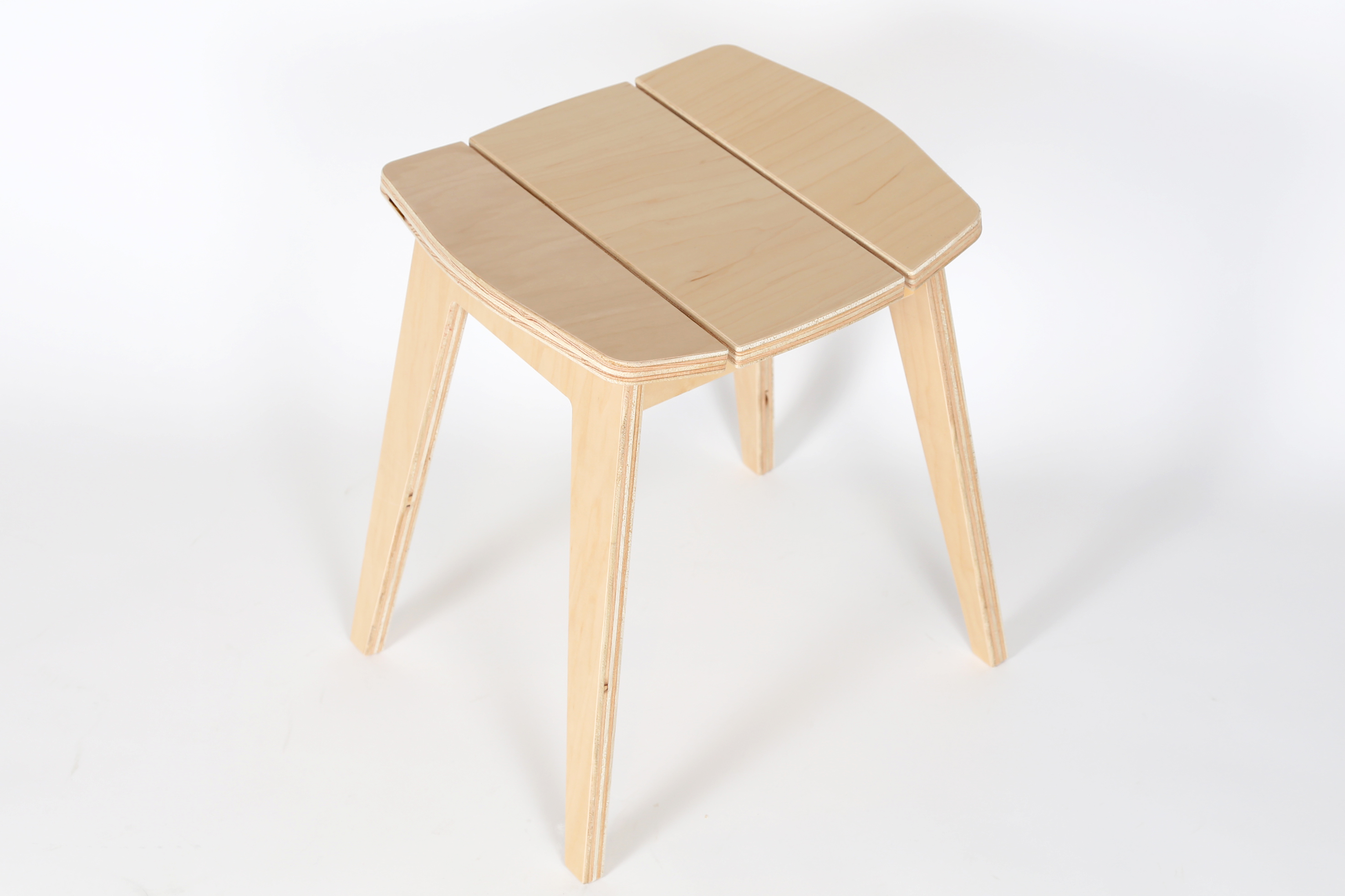
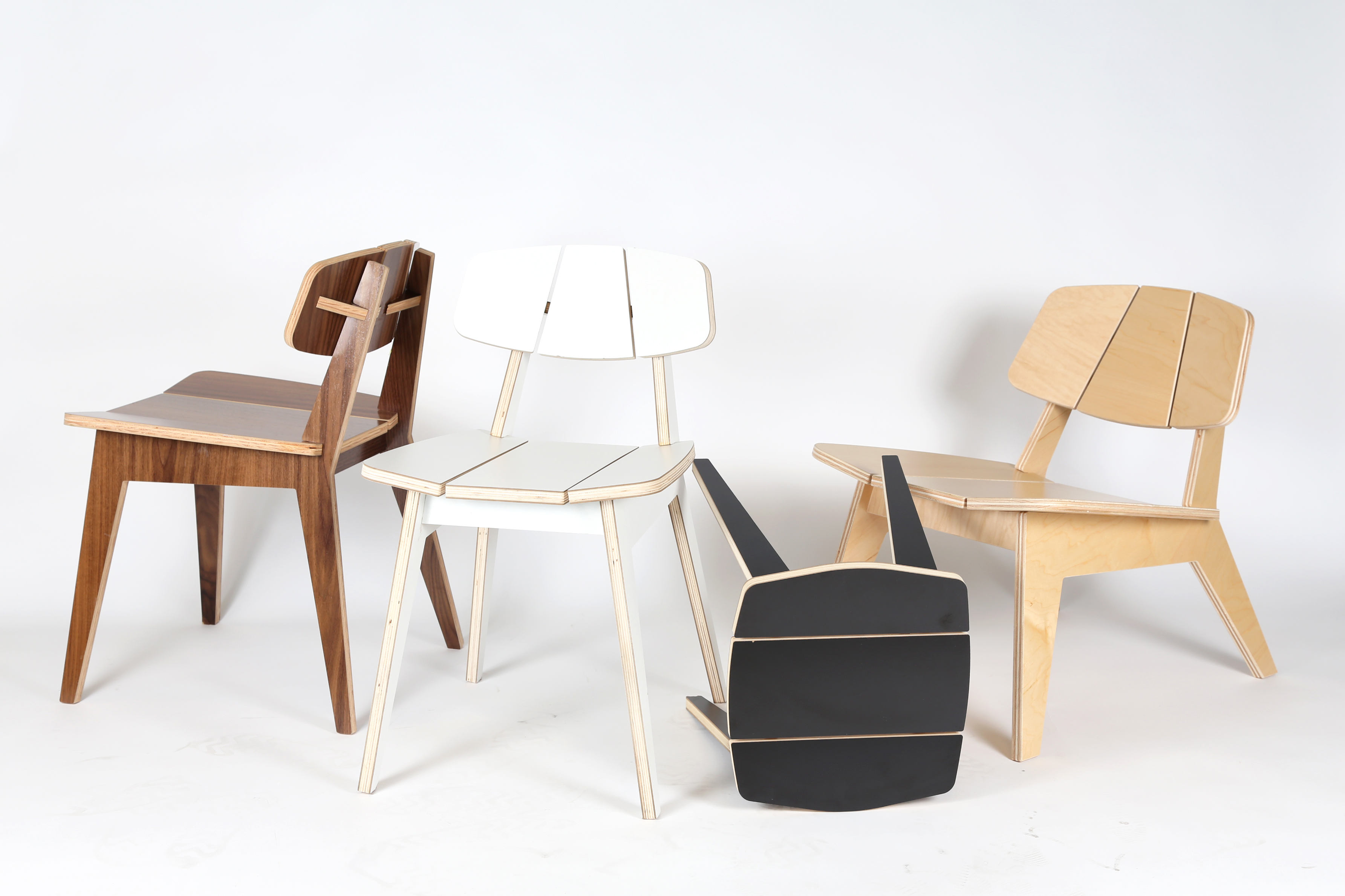
CNC Furniture has been for a few years already but hasn't really taken off. I believe this is because designers haven't spend enough time designing with that technology in mind. Most of the CNC furniture I found online have the typical joinery exposed or have a rigid feel. I played around with the ShopBot Buddy (worktable 4' x 2') and made a family of chairs: Lounge Chair, Dining Chair and this Stool. Click on the links for each instructable.
CNC Routers have become affordable in the last couple of years and there are quite a lot of DIY CNC Routers out there. If you have a TechShop close by you can probably make it over there.
Materials
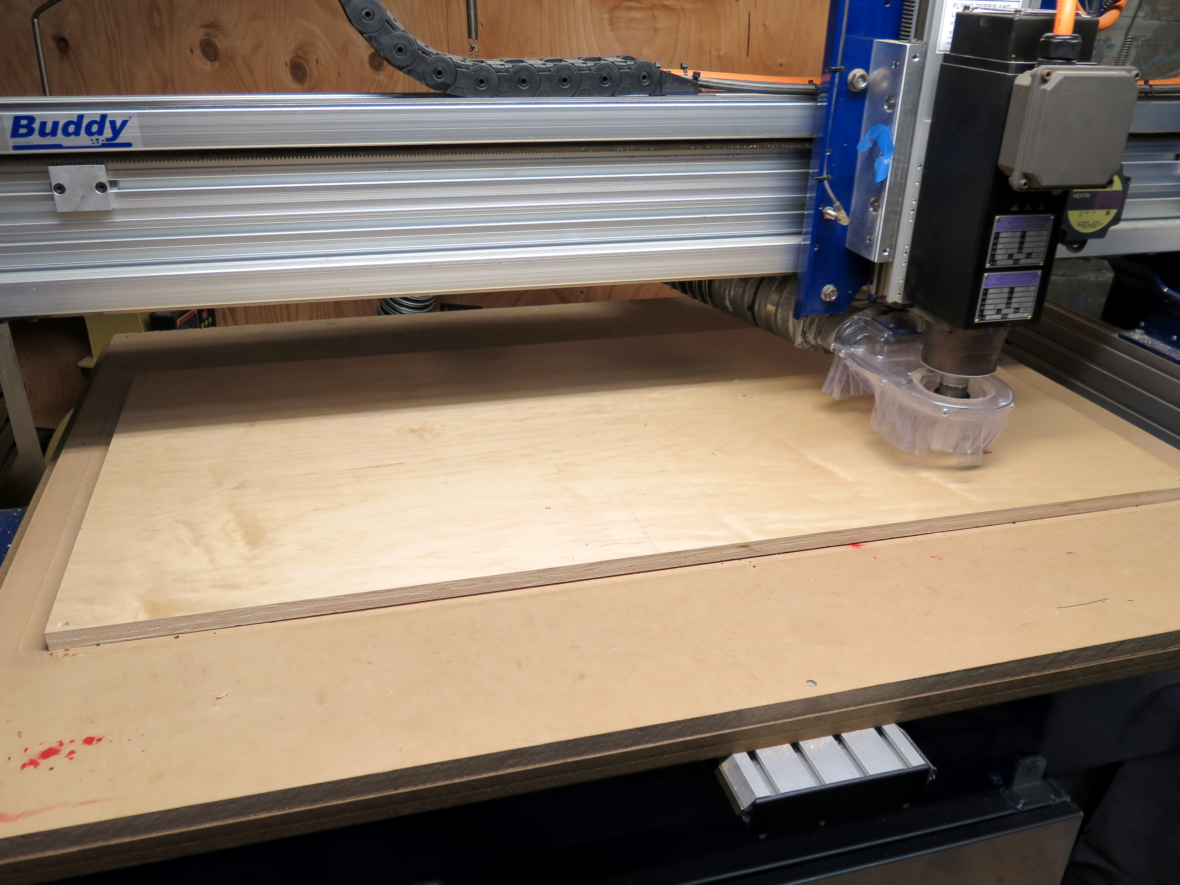

Materials:
- ¾ inch black melamine plywood (1 sheet 4'x2')
- Shopbot
- ¼ inch End Mill
- Table Router with round bit (optional)
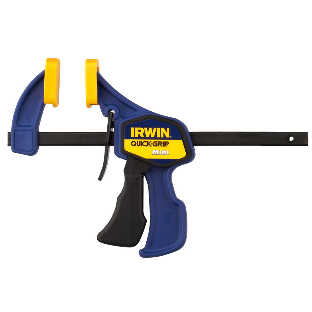
- Wood Clamps
- Wood Glue
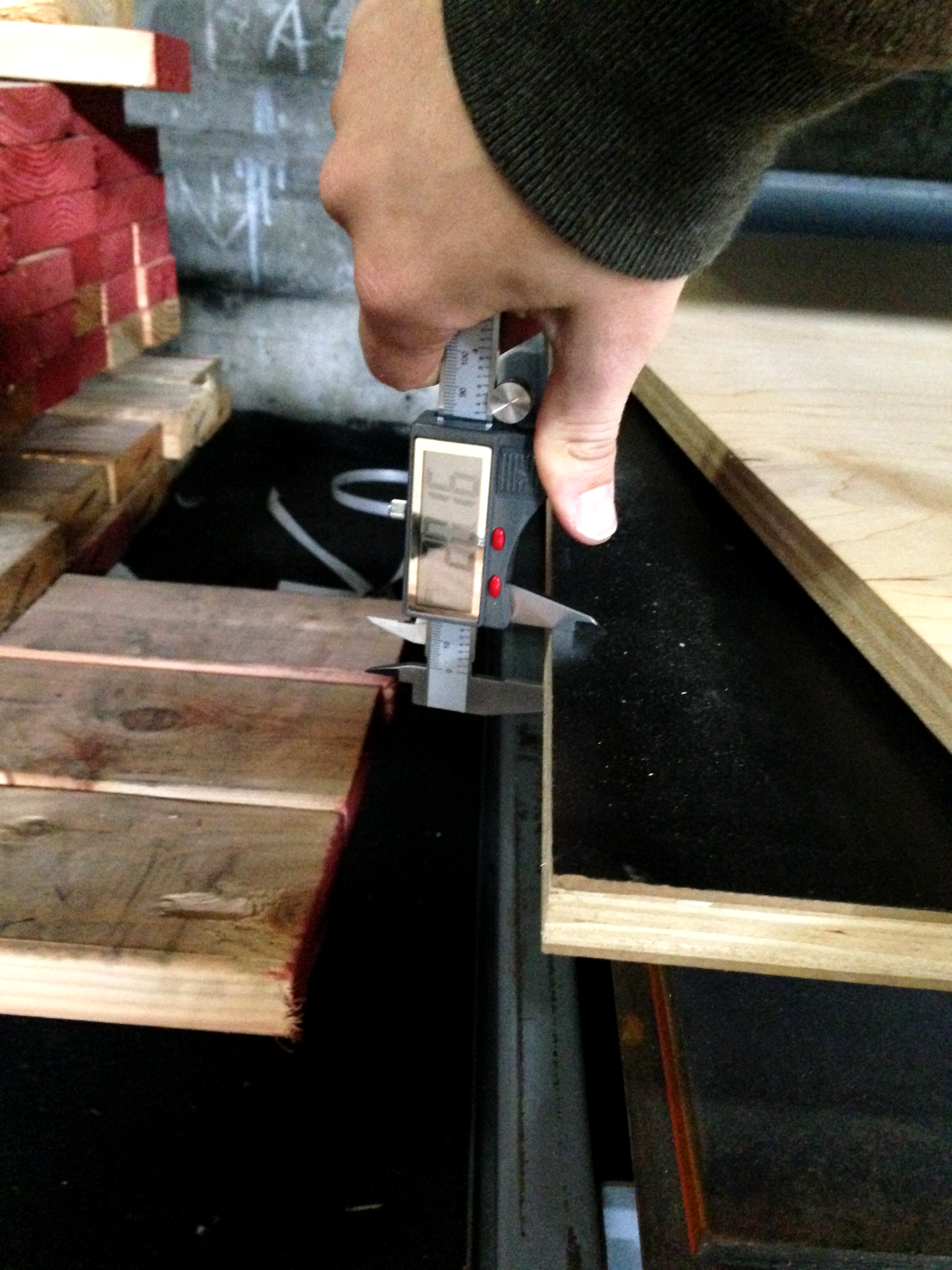
IMPORTANT: measure the thickness of your plywood! I purchased the black melamine plywood in 0.75” thick (19.05 mm) but as you can see from the photo, it was 20.16 mm thick. This is really important to take note because the design has locking parts and we need to accommodate for a thicker material.
Design and Prepare Vector Work
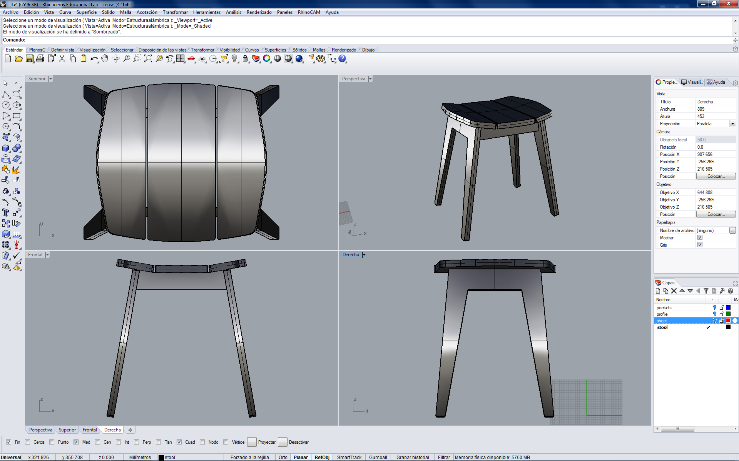
I used Rhino to design the lounge chair as I've been using it for the last 10 years. I took some measurements from other lounge chairs to have a sense of what the overall dimensions, specially the height, angle and width. You can edit the files as you wish and make a custom version for your own.
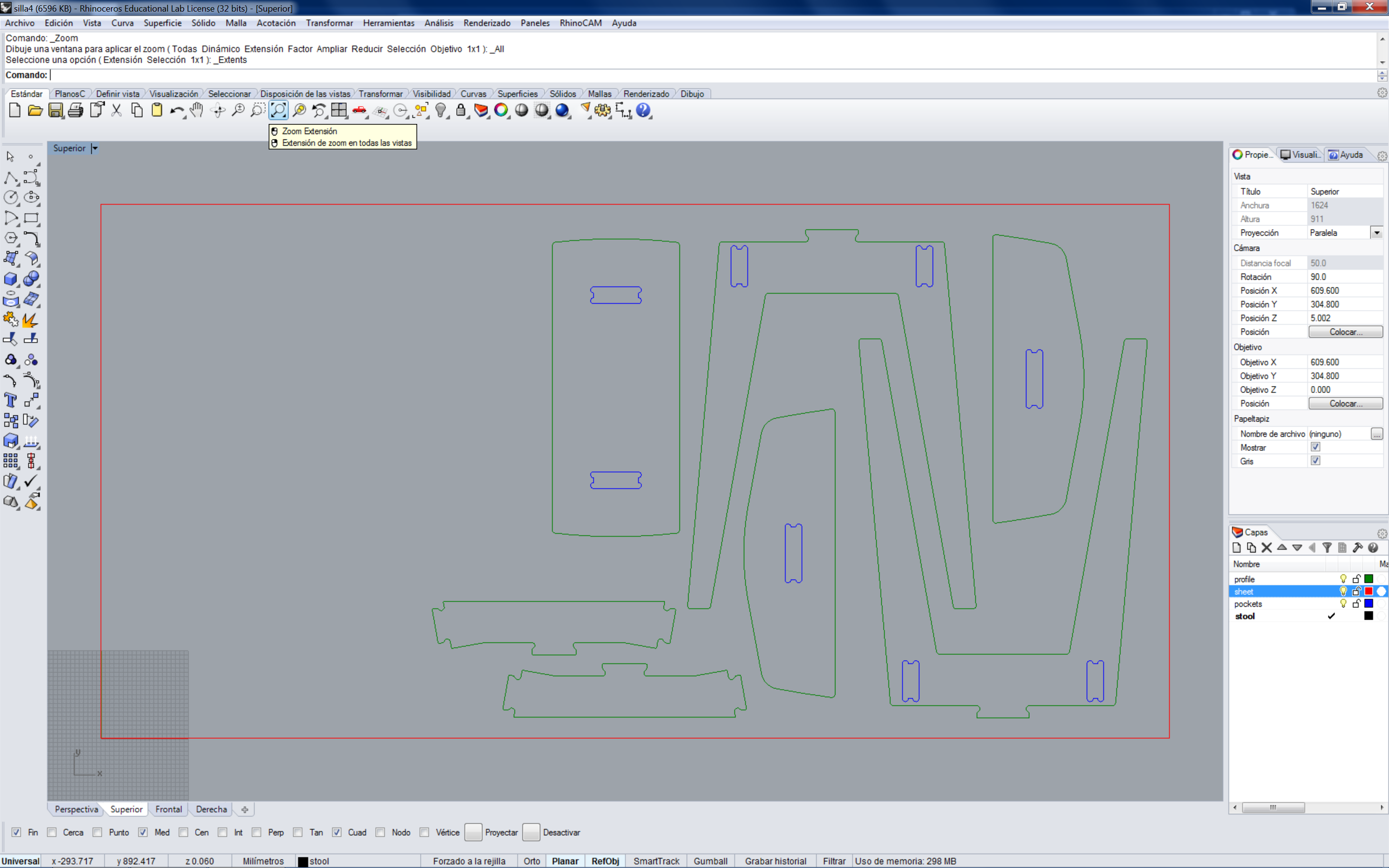
As you can see from the 2nd image, the stool fits in less than a 4' x 2' plywood sheet (that was how big my working table on the ShopBot is) and it is very fast to cut and assemble. I recommend that if you want to make the whole family of products you start with the stool. You can download the Rhino file and STL to play around and edit the design. Once I had all the flat pieces I arranged them in 4’ x 2’ sheet. Download the illustrator or Autocad file that you will need to create the toolpaths.
Note on woodgrain direction: This is an aesthetics warning. The orientation you give to every piece will matter once they are put together. For example, it is nice to have the seat match in orientation because the wood grain will be continuos. The seat is composed by 3 pieces and it will look inelegant if each one has the wood grain going in different directions. You can see from the 2nd image that all of the seat parts are going in the vertical direction.
Files included:
- stool.3dm - Rhino CAD drawing
- stool.stl - for a 3D preview
- stool.dwg - Autocad vector in mm.
- stool.ai - Illustrator vectors in mm.
PartWorks: Creating Toolpaths
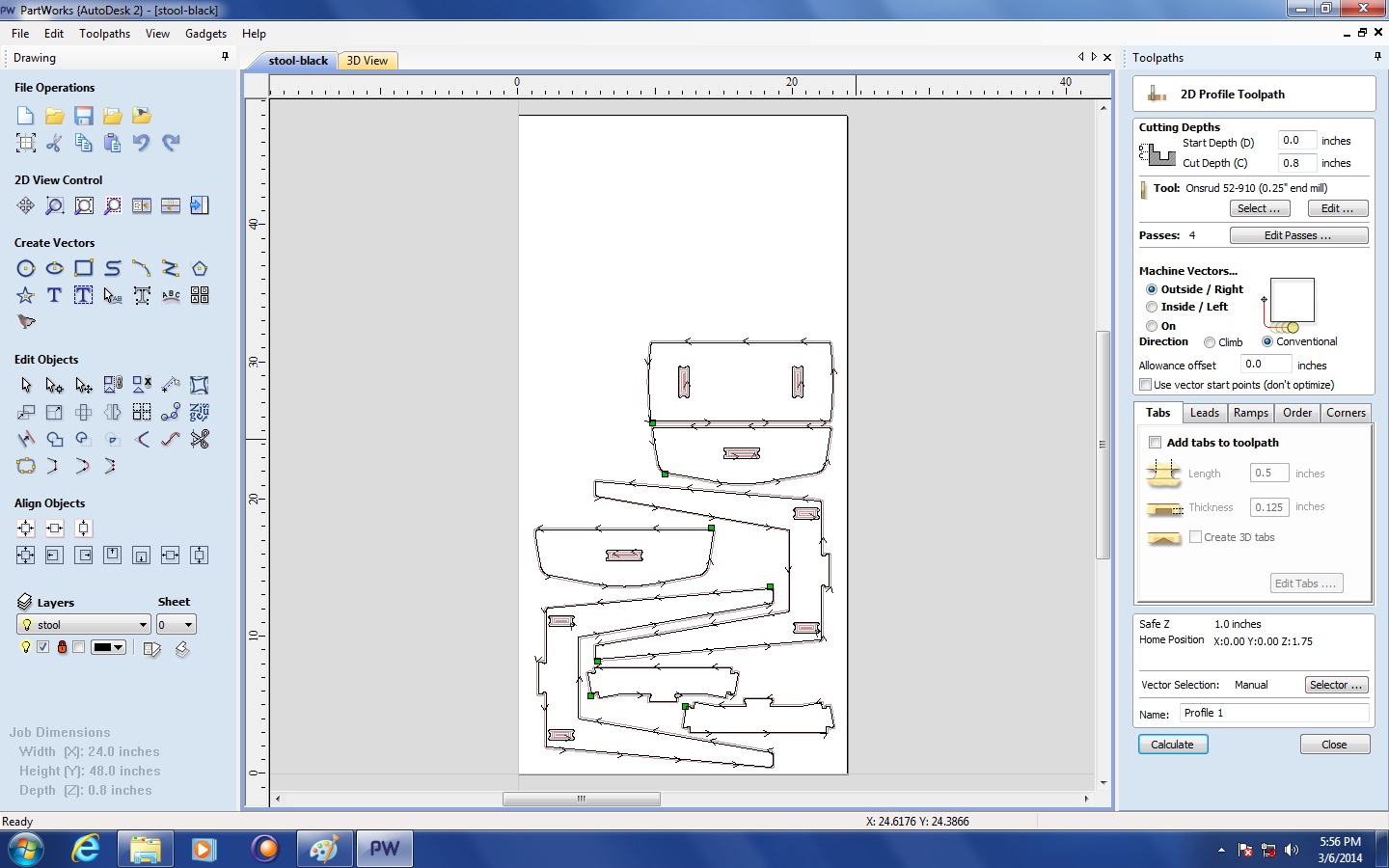
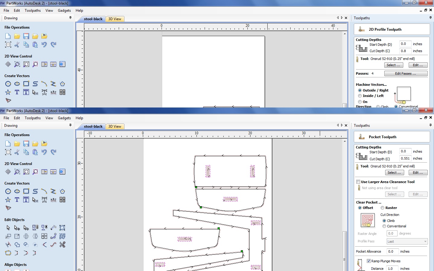
Create a New File.
Now in Job Setup: We will create a file with the size of our material: 4' x 2' x 1/4" (or how thick your true material is). Zero on the top.
Import Vectors files and your vectors will appear on your sheet. Sometimes your vectors might be outside the sheet so will need to zoom out.
Another thing you need to do is actually joining open vectors, under the section Edit Vectors. Control+A will select all of the vectors and then hit the Join button. Hit the Join button again.
If you need to correct or move some objects around the sheet now is the time to do it. You might want to do this to optimize material.
Control + A (select all), click on the right tab: Toolpaths (pin it so you have it open for the rest of your session).
POCKET TOOLPATH:
Under the Toolpath Operations you will see a few options. We will begin with Pocket Toolpath that will clear an area as deep as we want. You should always start with pockets because all of your material will be in place - for example, if you start with a Profile cut and your piece moved because you didn't have tabs (or they were too thin) you will have a loose part and your pocket will be made in the wrong place.
Select your vectors that we want to pocket. These are all the small closed vectors that look like a dogbone and they are inside the cut pieces.
Click on “Toolpath” tab on right side of screen. Under “Toolpath Operations” select “Create Pocket toolpath.”
Start Depth: 0” (starting on top of material)
Cut depth: Choose a finished depth of cut which will be less than 3/4 ". I used 0.551" but if you want to change it you will also need to change the dimensions of the part that fits inside.
Now you need to select the Toolbit you will be cutting with. Under Tool, click on Select and use a 1/4 inch End Mill
We are going to select Offset that will follows the contour of the design. Select Climb.
PROFILE TOOLPATH:
The 3rd icon is for Profile cut and a fill in sheet will appear with options. The first set of values will determine how deep you want to make the cut. Our start depth will be zero since we zeroed on the top of the surface. You want to cut all the material and a tiny bit of the sacrificial board so add a little depth to your Cut Depth (C).
Now you need to select the Toolbit you will be cutting with. Click on Select and use a 1/4 inch End Mill.
Since we are cutting the pieces mark on Machine Vectors: Outside/Right.
Add Ramps to Toolpath, Smooth, pick a Distance (4-6 inches works well).
Save Toolpaths: You will be prompted a "WARNING - Tool will cut through material" but you know that already because you did that on purpose when you selected the cutting depth. Once you succesfully created the toolpaths you will see a preview. Once you are satisfied with what you see, hit Close.
Make sure you select Pocket1 and Profile1 and hit Save Toolpaths, it will have an extension SBP.
NOTE ON CREATING TABS: Tabs are pieces of your material that won't be cut to hold the parts in place. Since I had quite a lot of parts to cut and I didn't want to do a lot of post-processing work I decided NOT TO MAKE TABS. If you have a worktable with vacuum then this is great because you won't need tabs anyway.
Zero X, Y and Z Axis
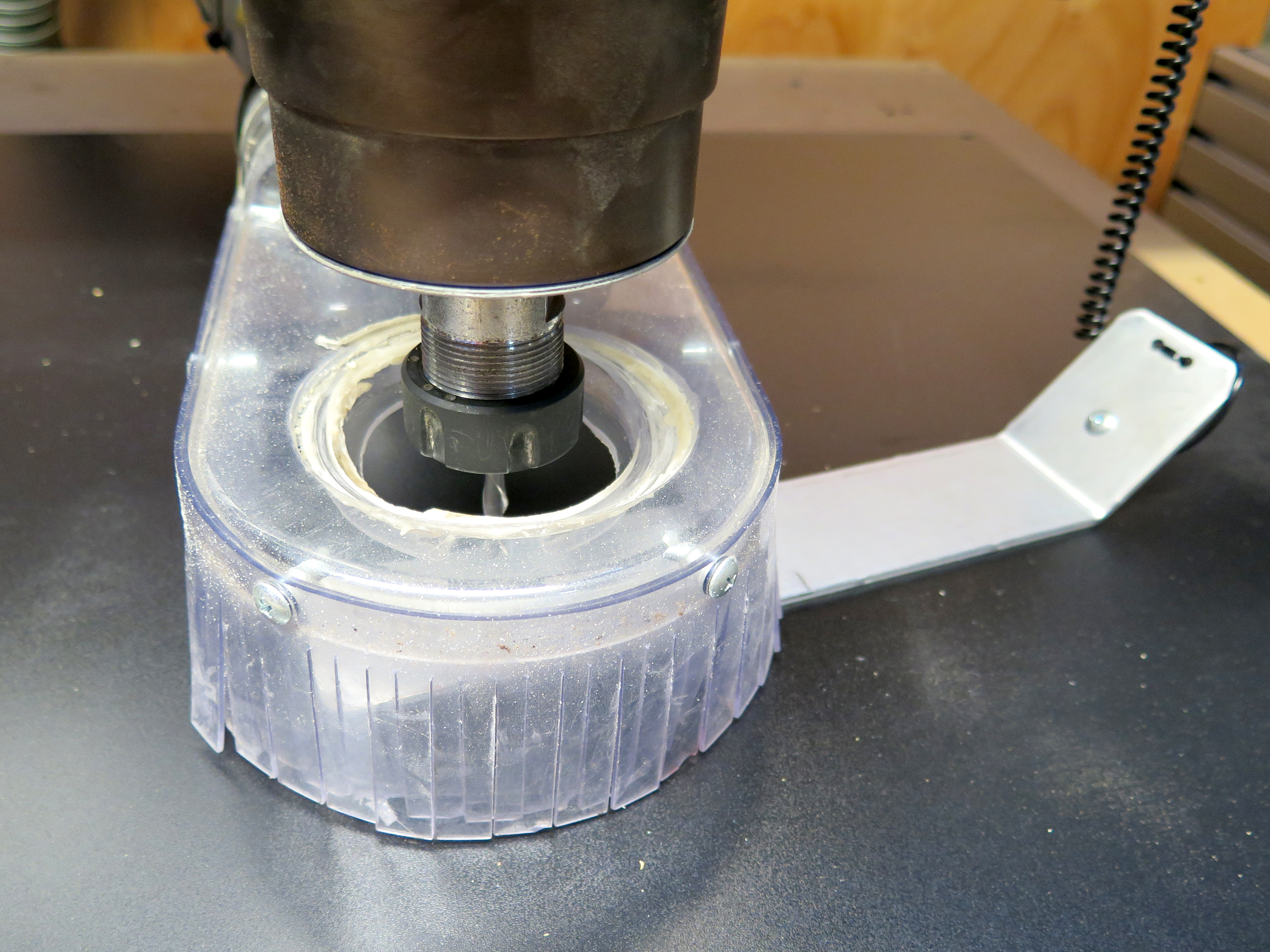
Now you are ready to cut the pieces for your table. Place your 4’ x 2’ sheet of ¾ plywood on the worktable of the Shopbot. Use screws to get the sheet down to the table.
Turn on the Shopbot and the Computer. Open the Shopbot manager. Put the ¼ inch End Mill on the Collet and you are ready to Zero the machine in 3 axis.
Use the proxy switches to Zero both X and Y Axis. Now use the Z plate to zero the Z axis of the Machine.
Zero Z Axis with Z Plate:
- Cuts - C2: Zero Z Axis w/Zero Plate
- It will prompt if we have the Zero Plate bellow our bit. Hit Enter when ready.
- It will now go down, touch the plate, go up and then slowly go down again to touch the plate one more time.
- It will prompt that it has been zeroed. Awesome, now you are ready to begin the cuts!
Run Toolpath File
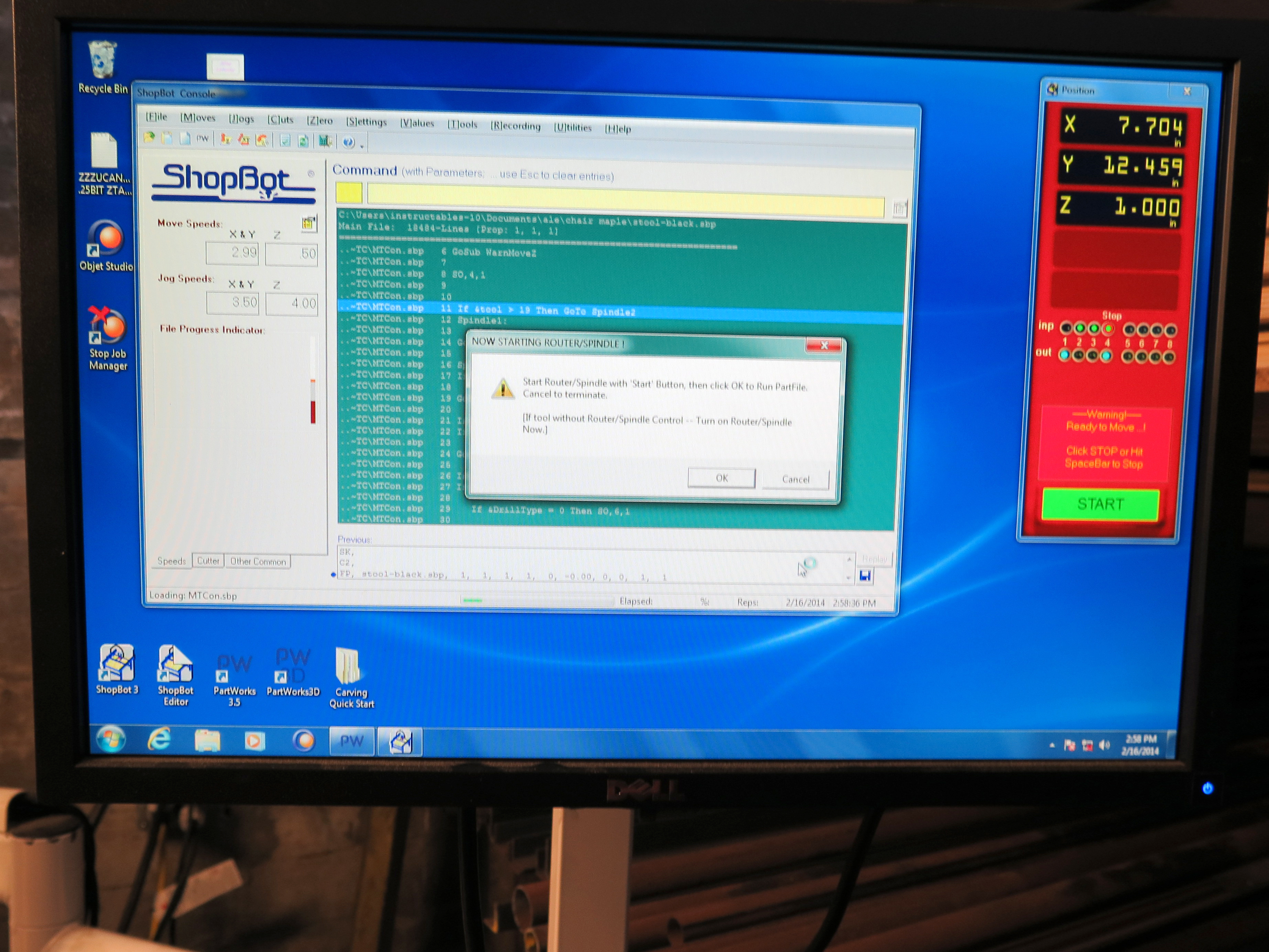
Open your Toolpath file and hit Start. You will be prompted a Warning message to start your Router/Spindle. Make sure you actually start the spindle before hitting OK on the Warning message.
The Shopbot will now begin to make the cuts on your material.
Watch and Remove Parts
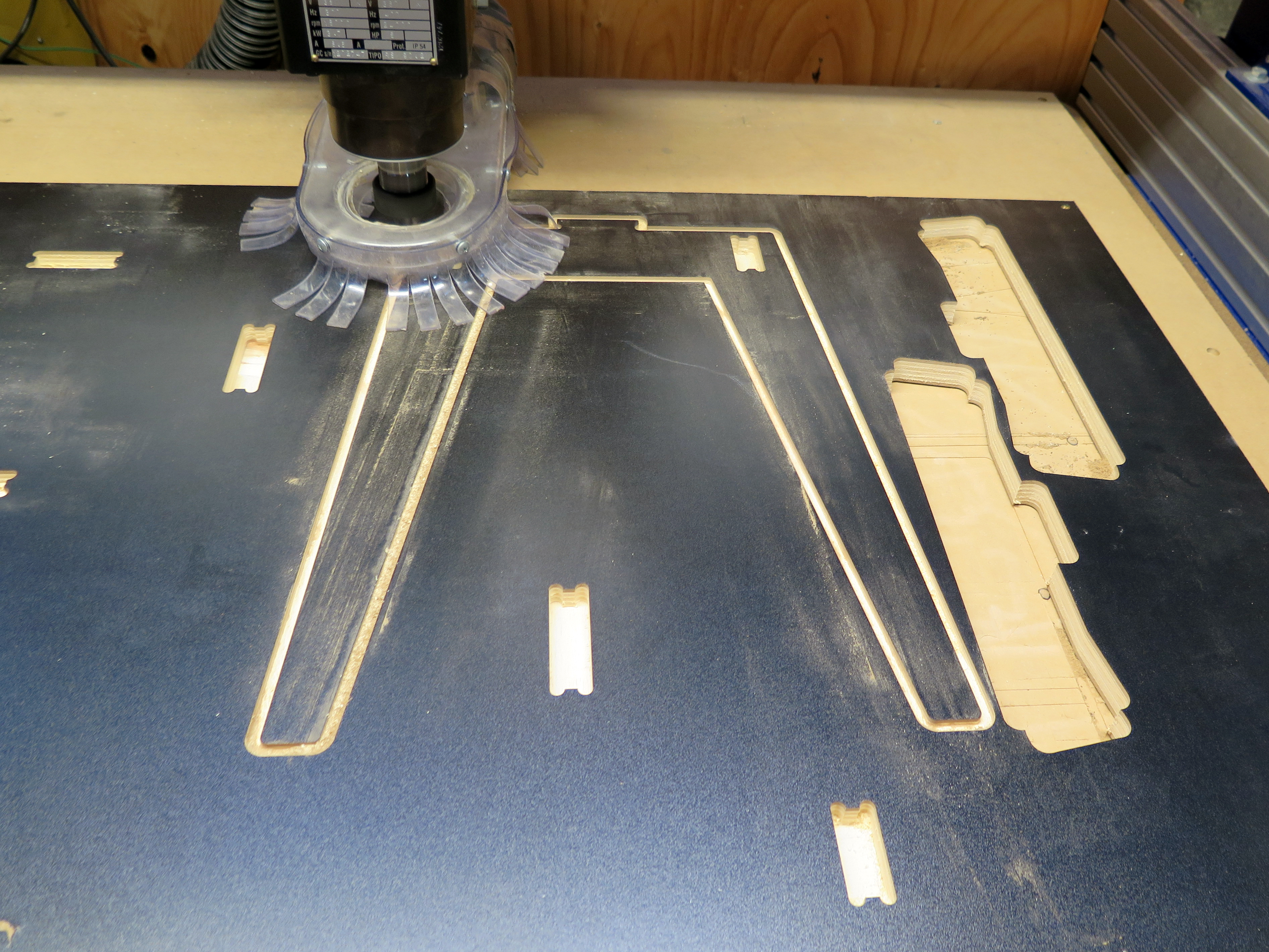
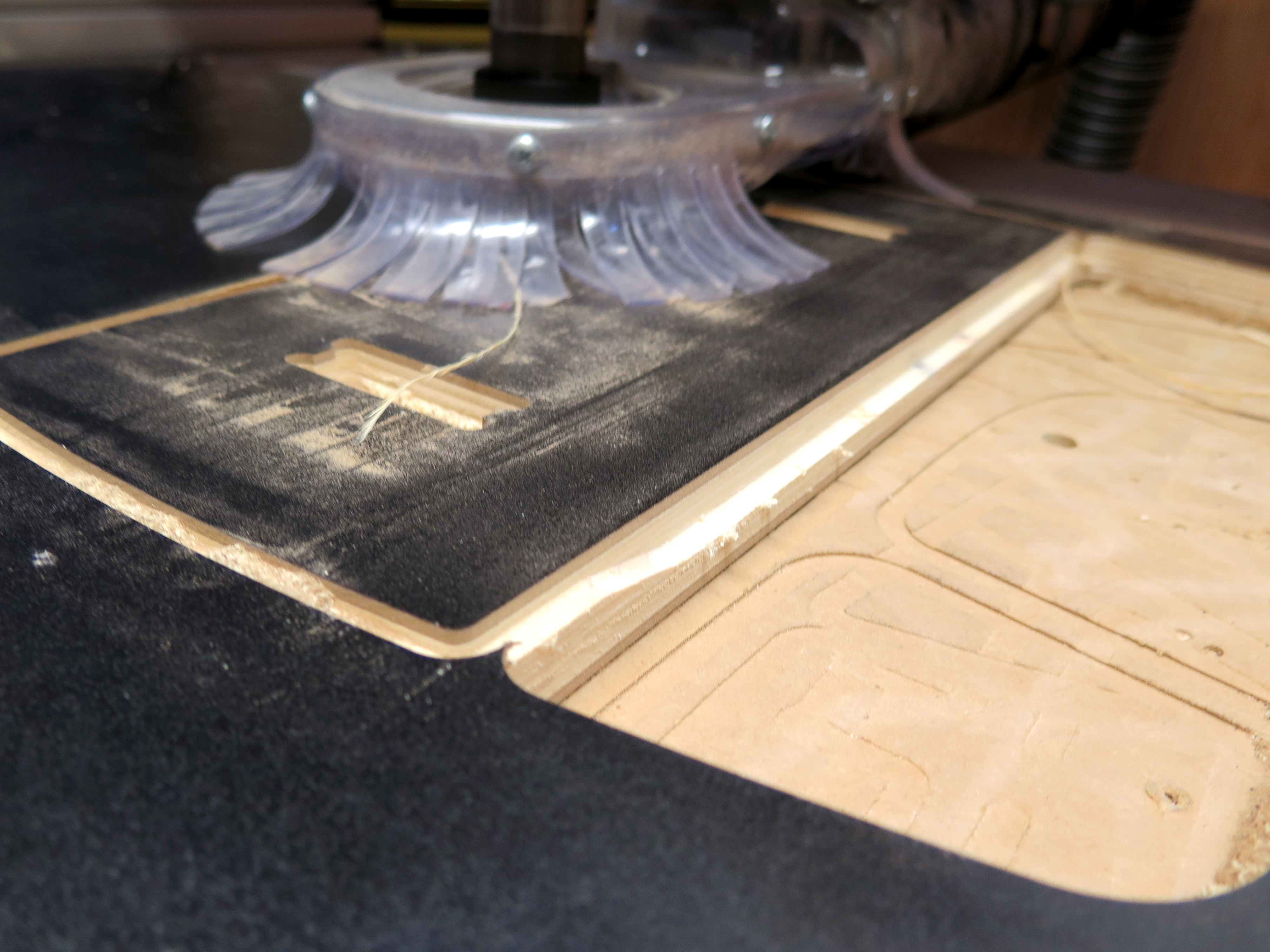
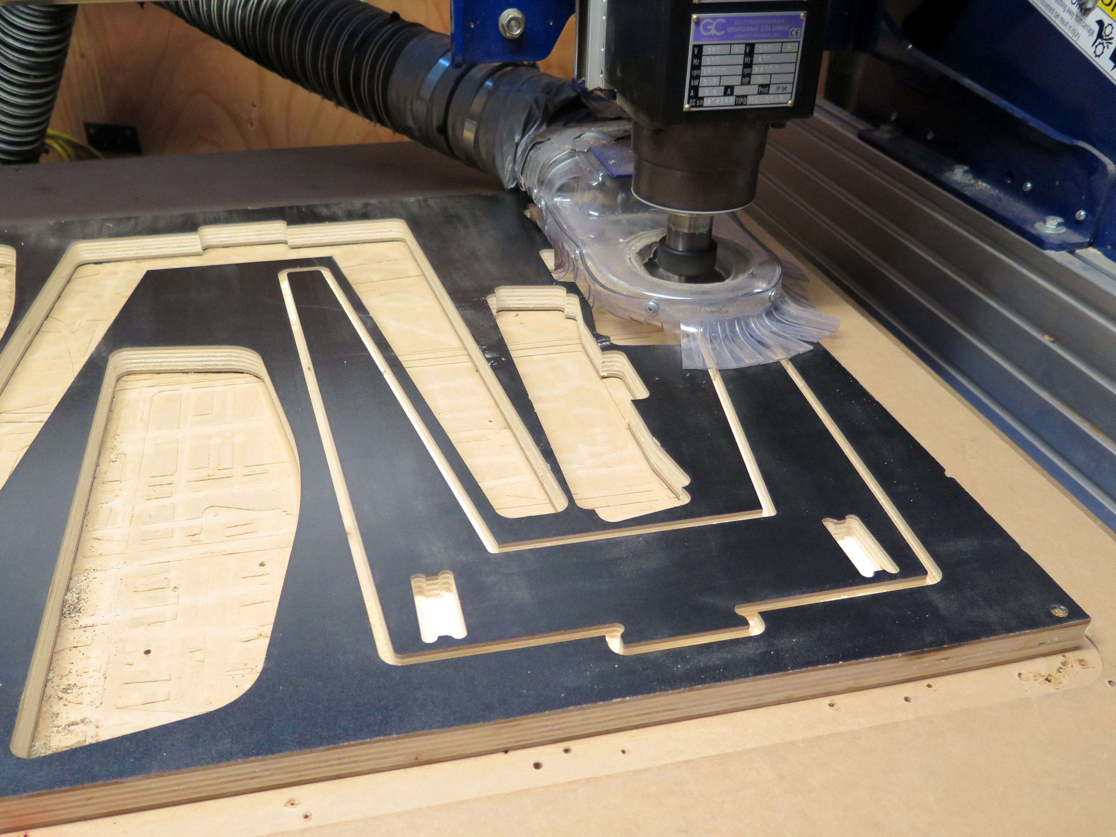
Now this is the easy and fun part. You sit down next to the router and watch how the machine cuts all of your pieces. Since I was using a ¼ inch End Mill it will make 3 passes before it actually cuts loose each single part. It will start by doing the pockets and then the profile cut.
Remember that we didn’t add tabs so if your pieces are really close to each other it might be a good thing to take your recently cut piece out of the table. I did this easily without stopping the machine. Once the job is done the Spindle will turn off automatically and you can unscrew your material off the worktable.
Organize Parts
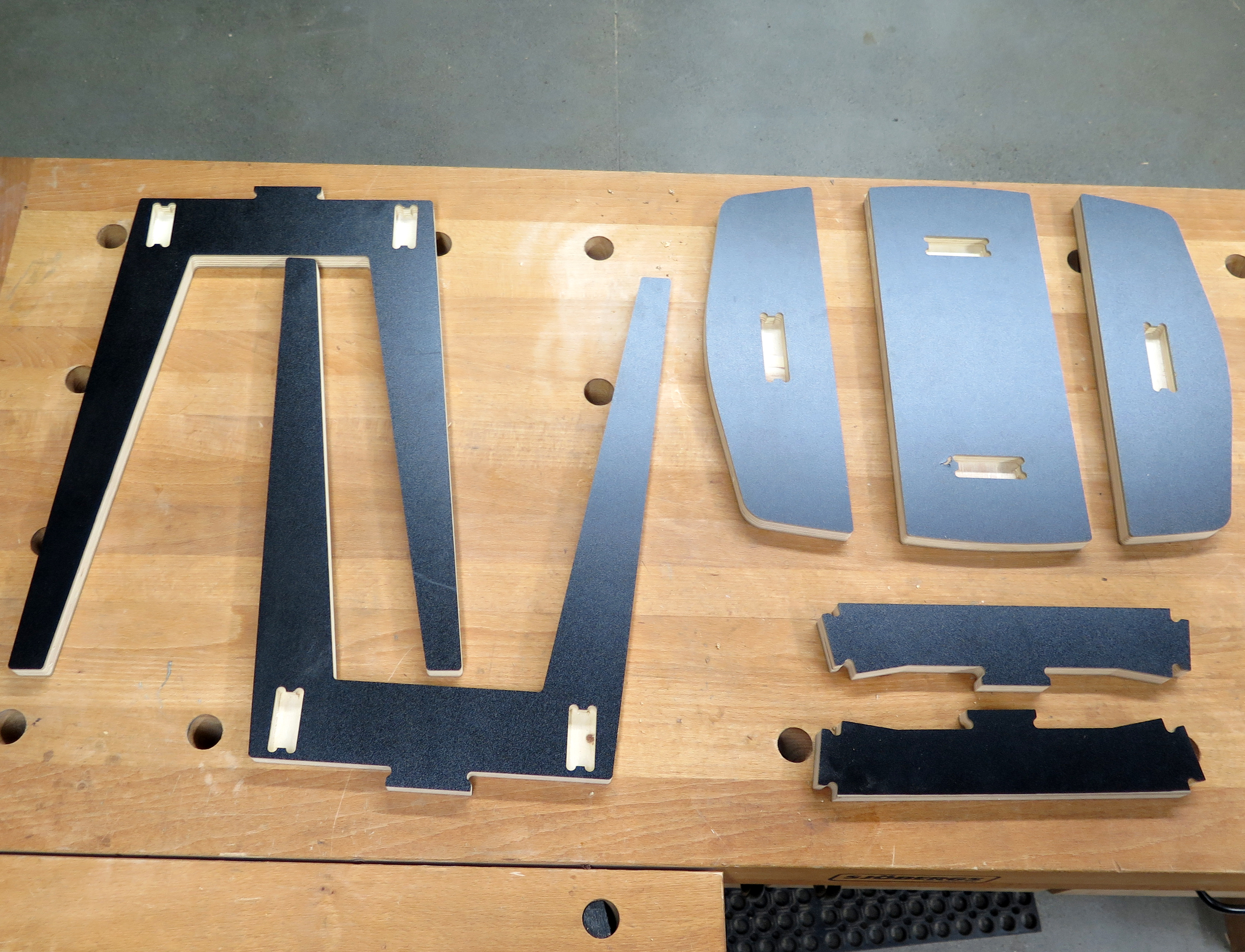
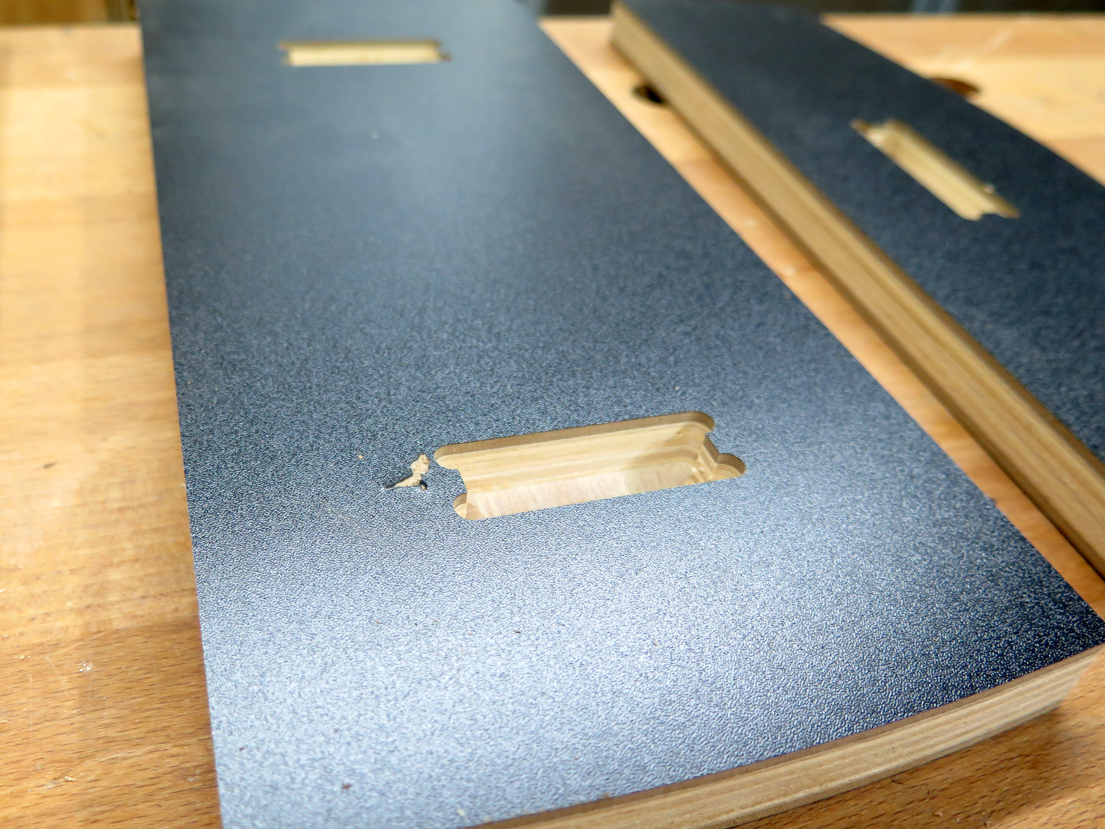
We have a few pieces and it is a good idea to organize them before we begin to assemble. We should have:
- 2 legs
- 2 supports between each leg
- 3 seat parts
Rounding Edges With Table Router
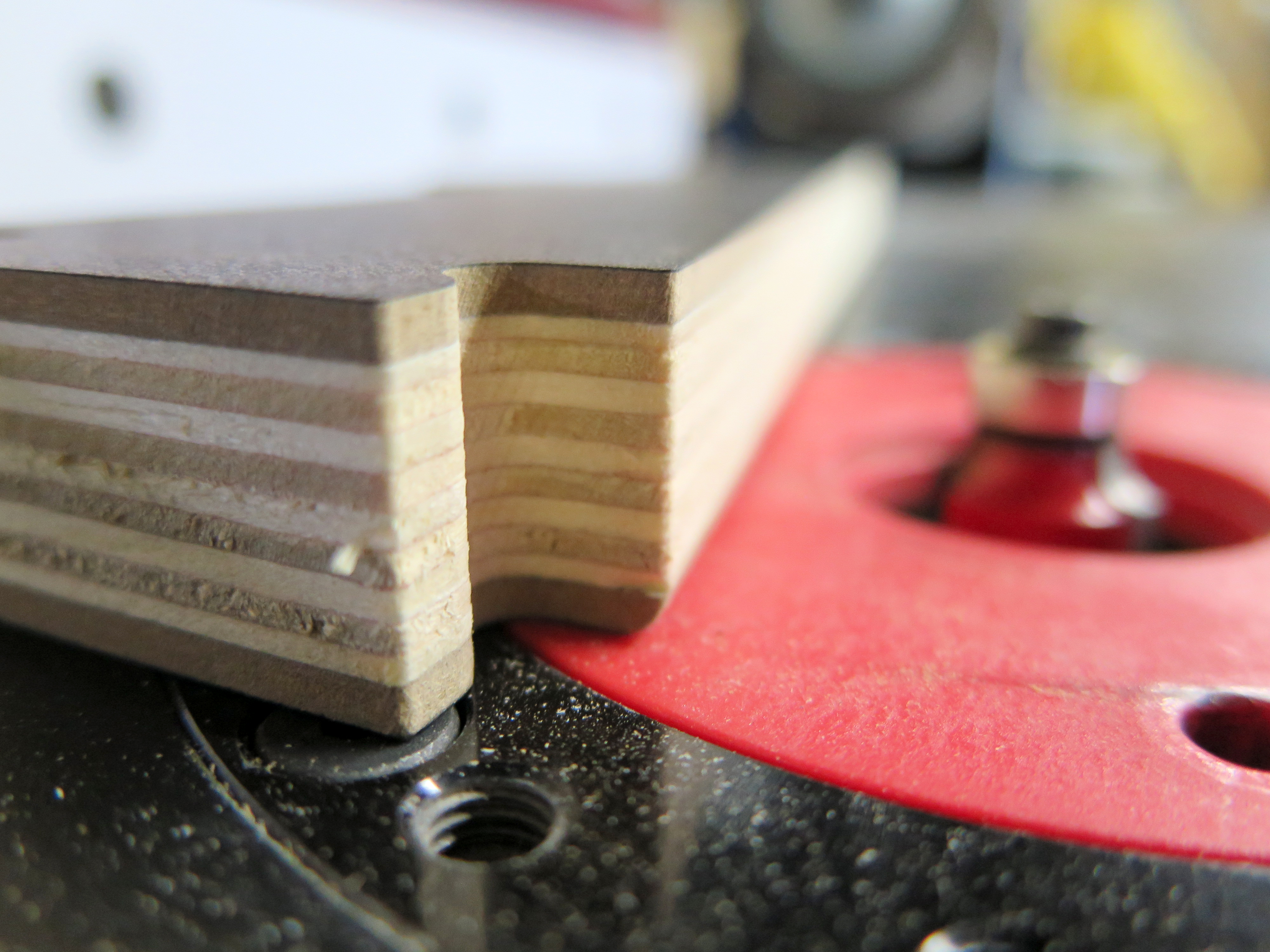
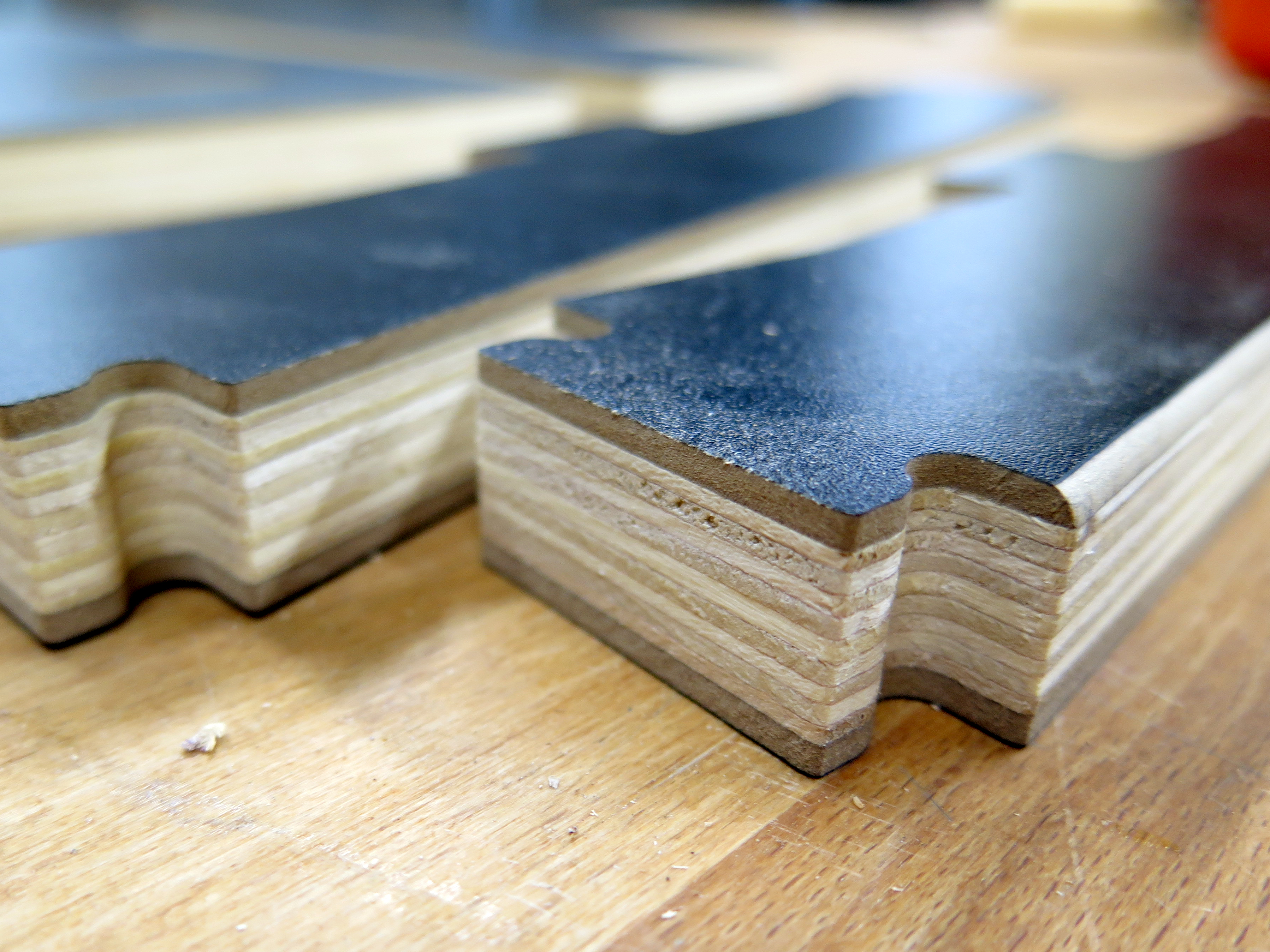
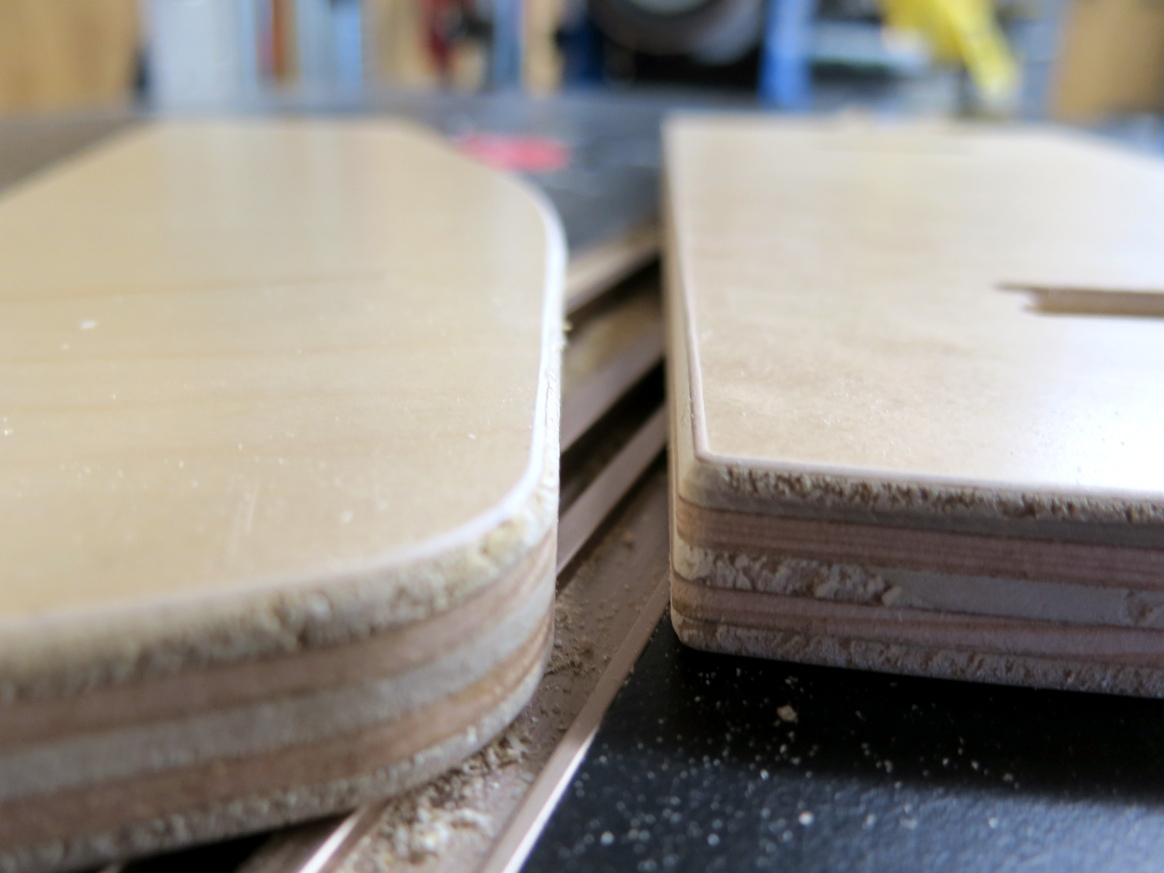
Before we actually assemble the parts I decided to round the edges of the seat (3 parts). I tested the black melamine plywood and wasn't really happy with my results because of the dark particleboard section before the actual ply begins. However, if you use another material such as maple plywood you can do this and it will look really nice. Check out the photos and compare.
The setup I had was really great: I used a table router and a small radius router bit. If you don't have access to a router you can sand the edges away with sand paper. It is good to practice with a test piece first to make sure the height of router bit is in the ideal location.
Assemble Legs
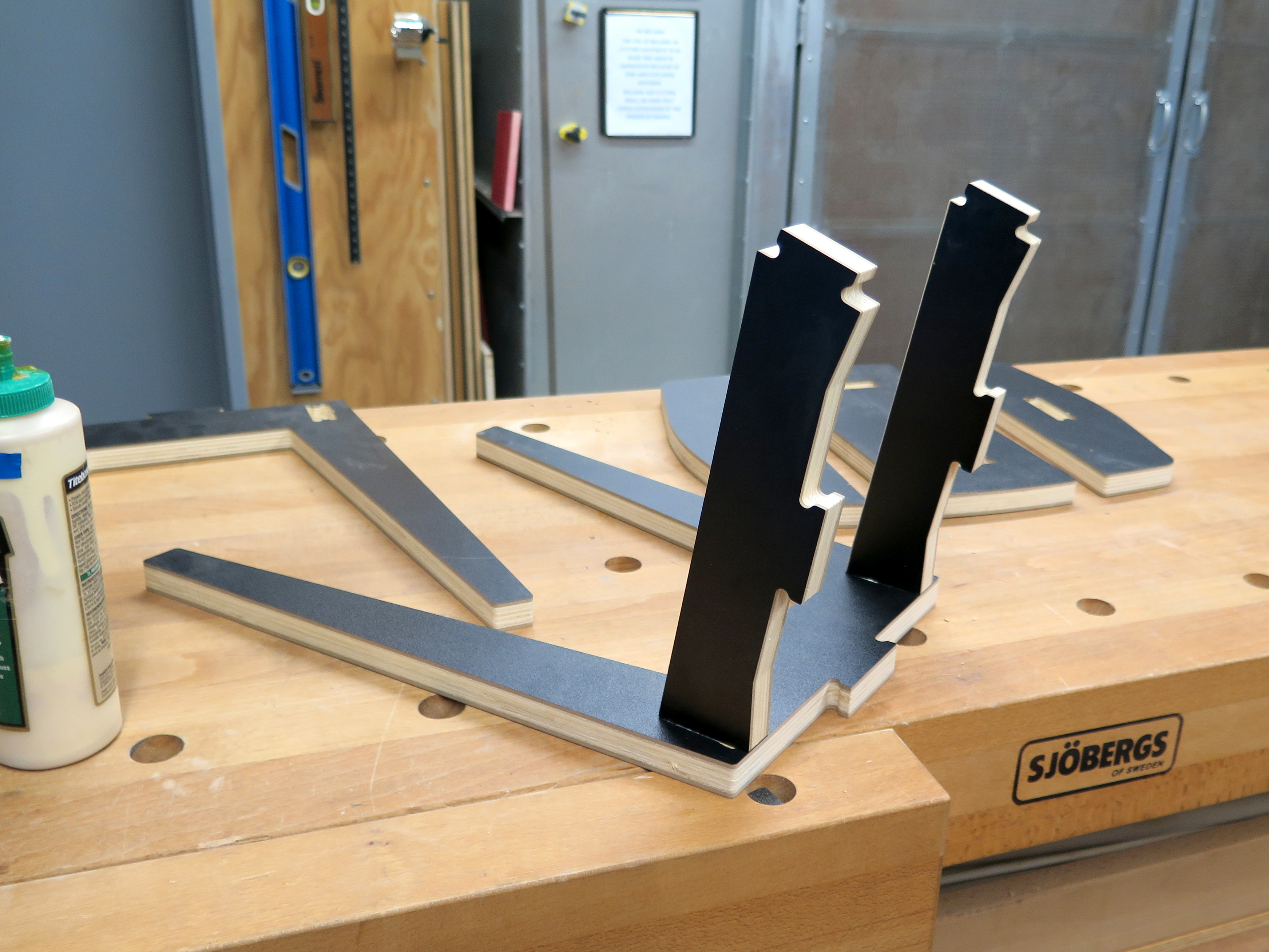
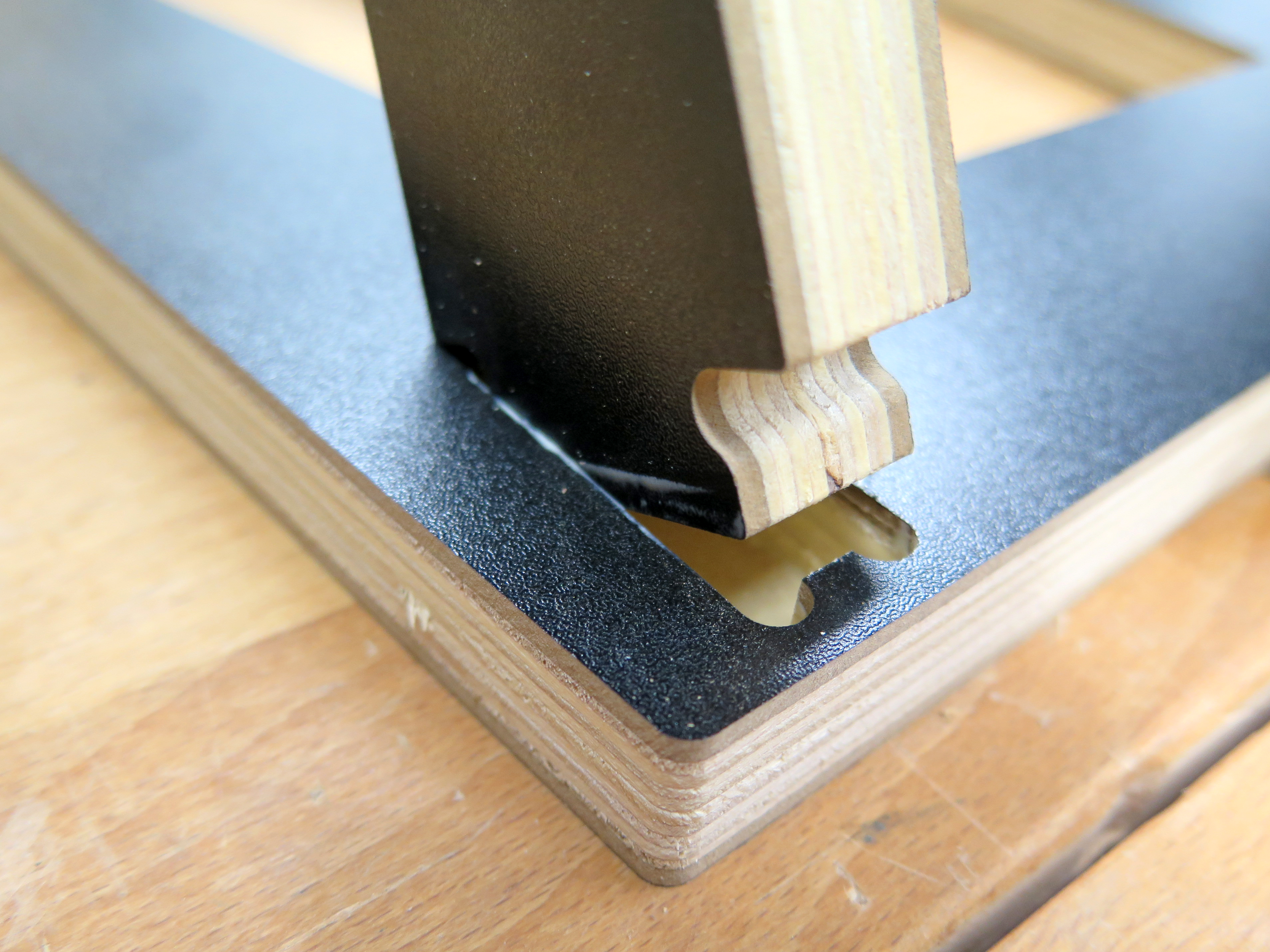
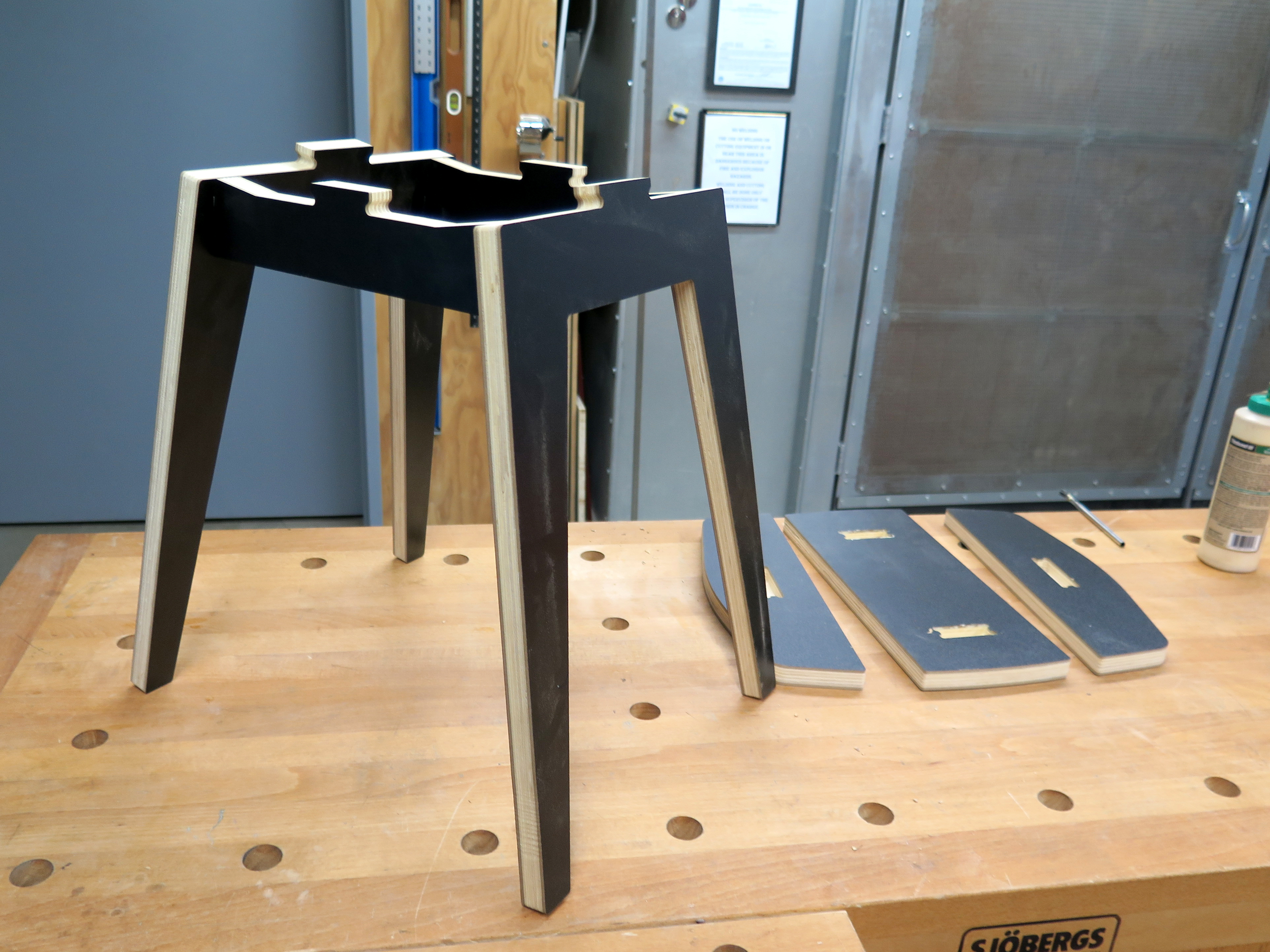
Now it is time to start assembling the pieces together. I started by gluing one leg to the 2 supports and continued gluing the other leg. Once I had it firm I used clamps and let it dry for 30-60 min.
Assemble Seat + Legs
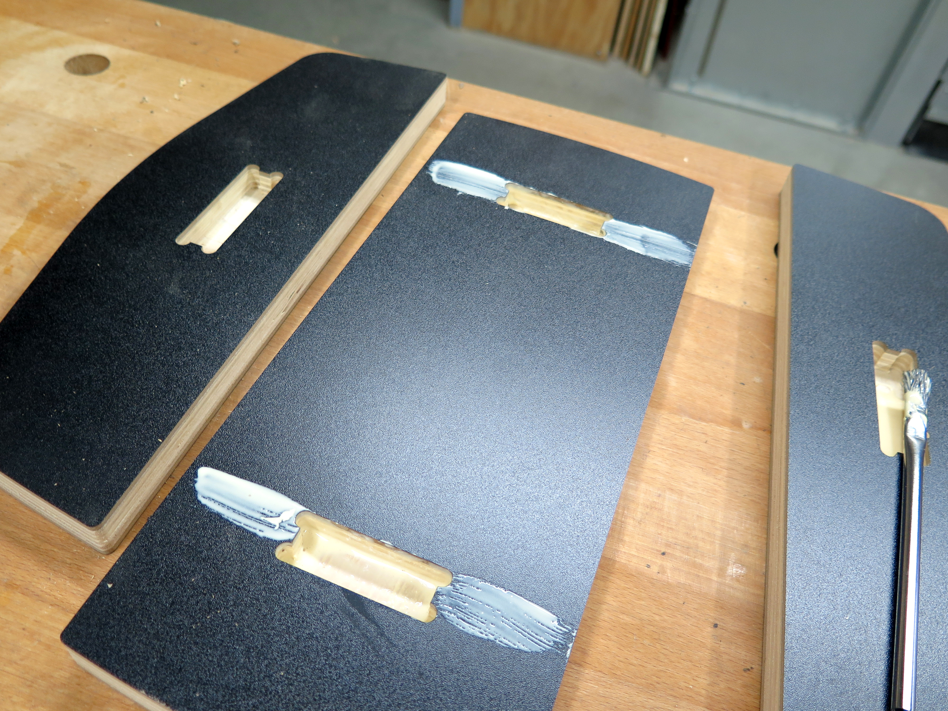
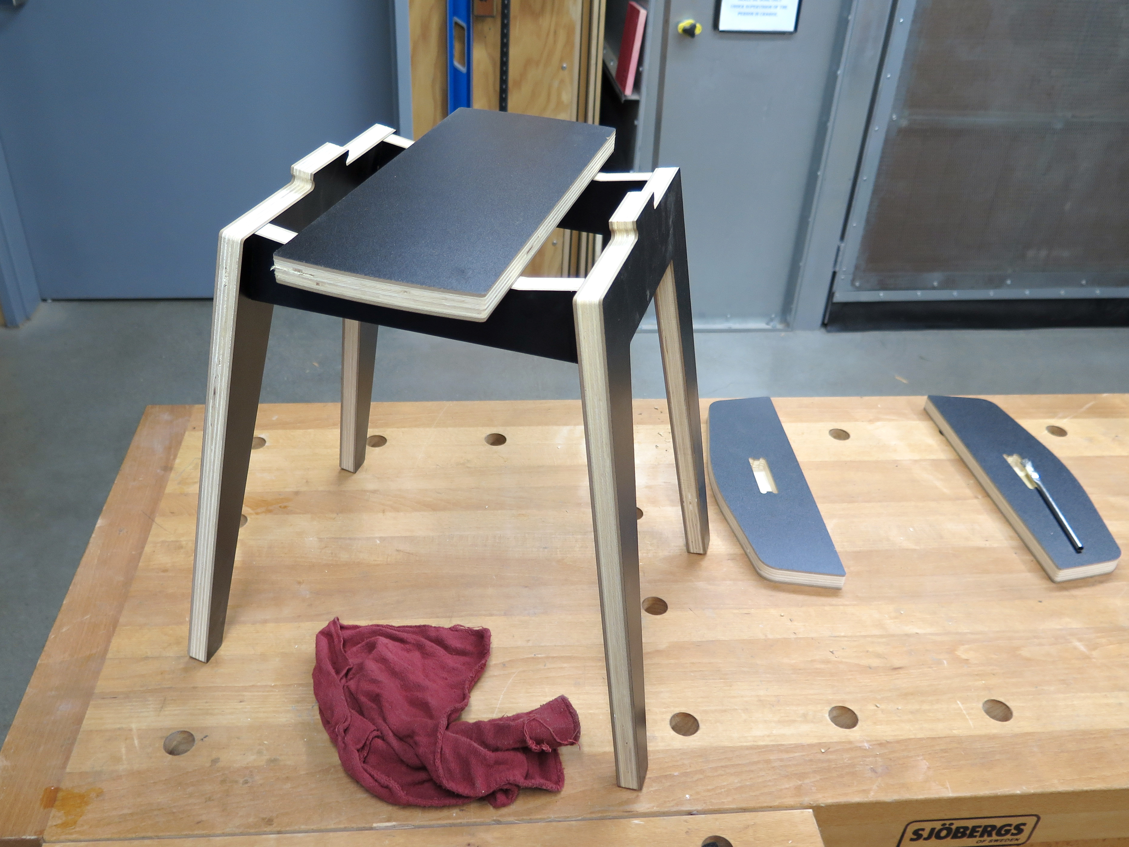
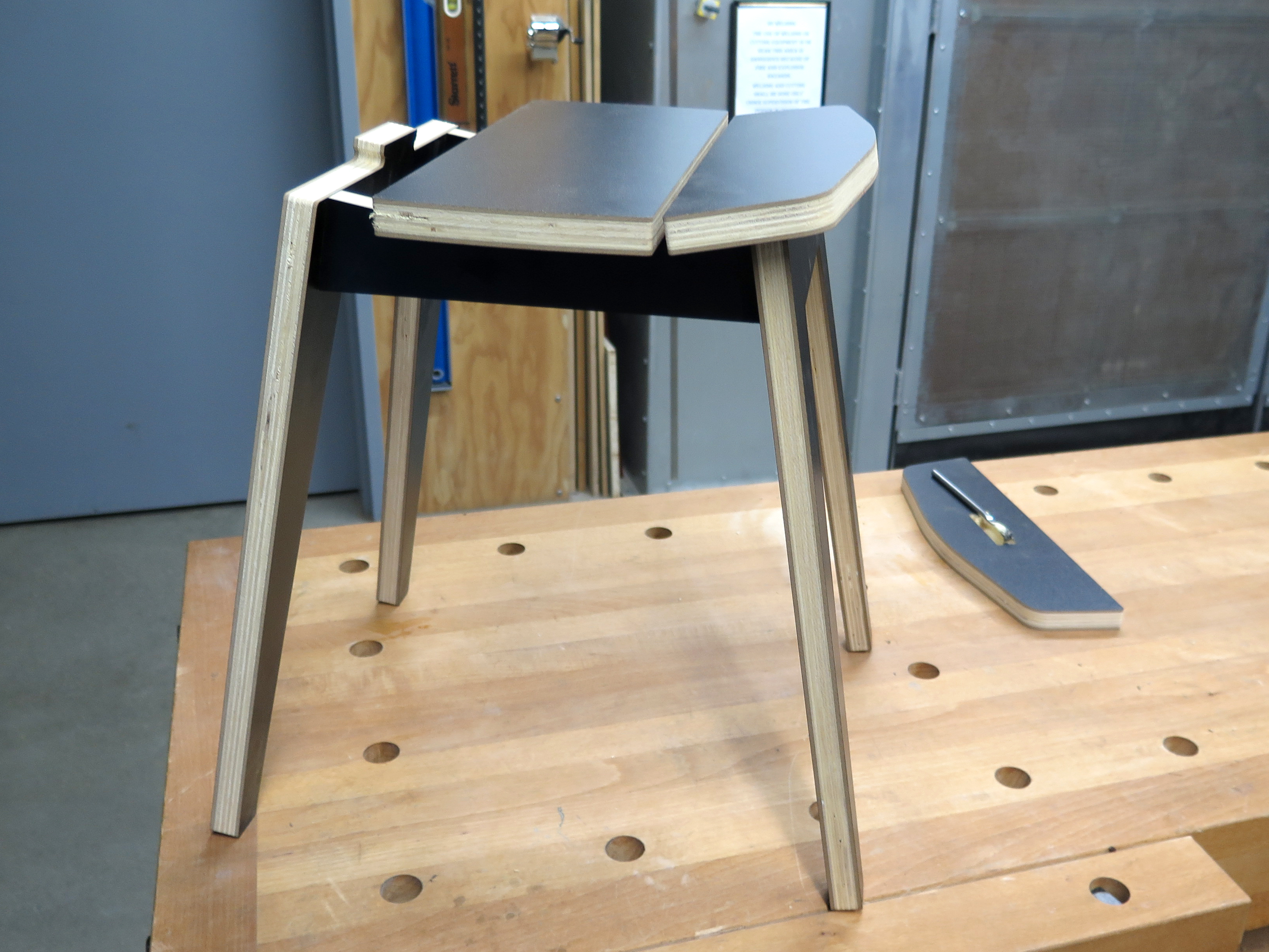
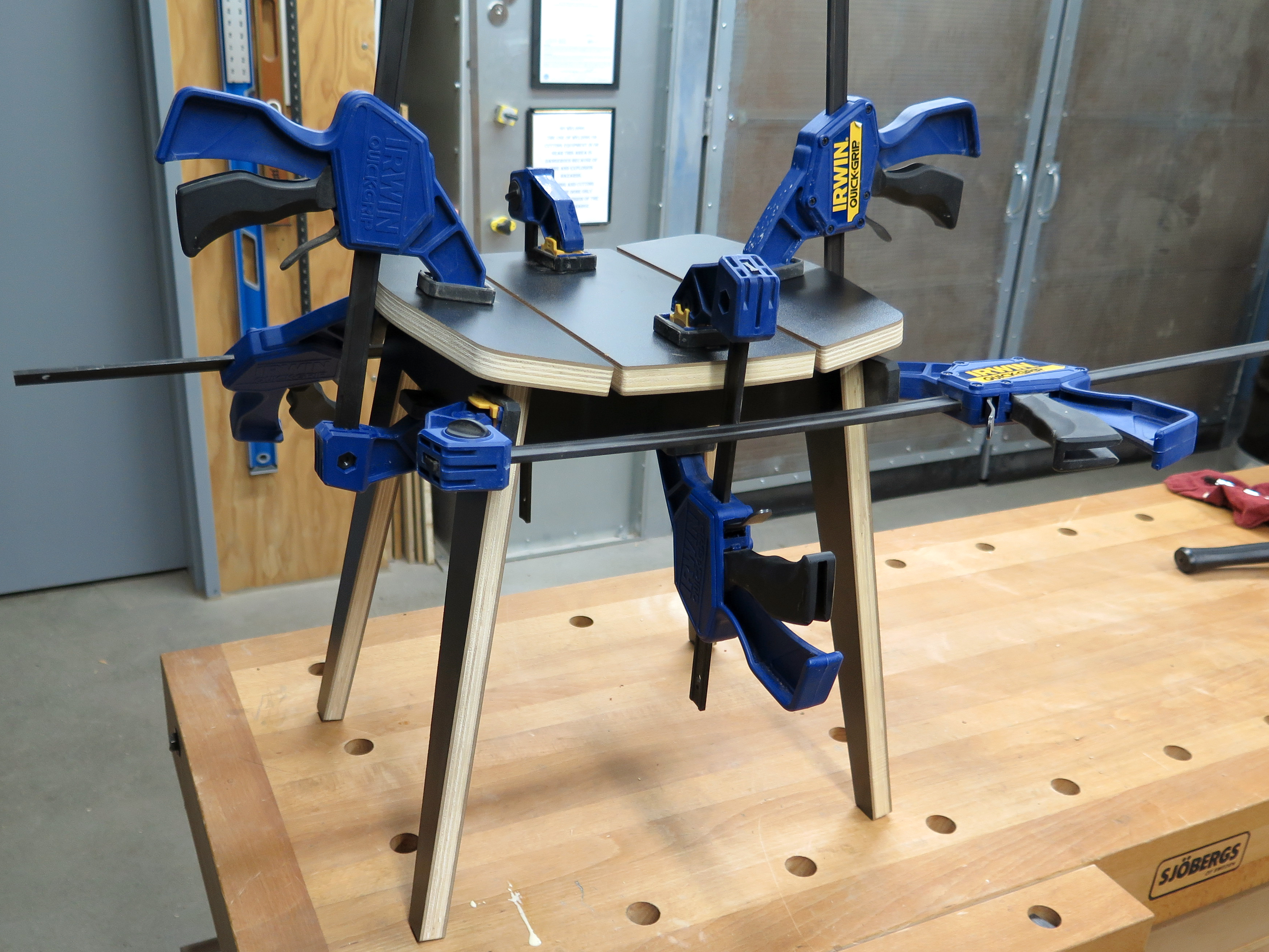
While the legs are drying up you can assemble the seat as well. Start with the middle section and then move to the sides. You can also use clamps and leave them to dry.
Enjoy
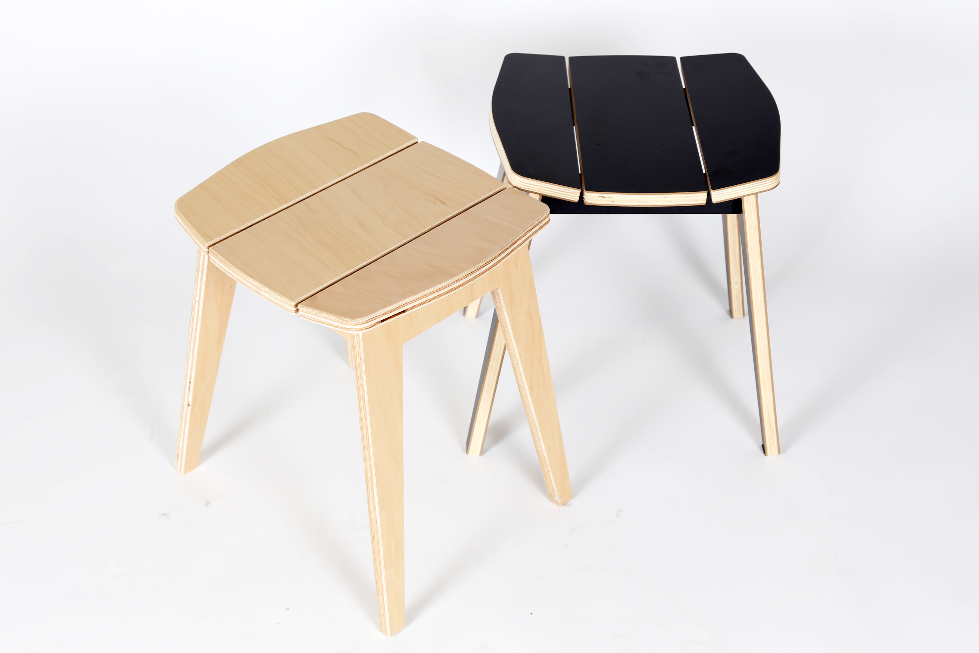
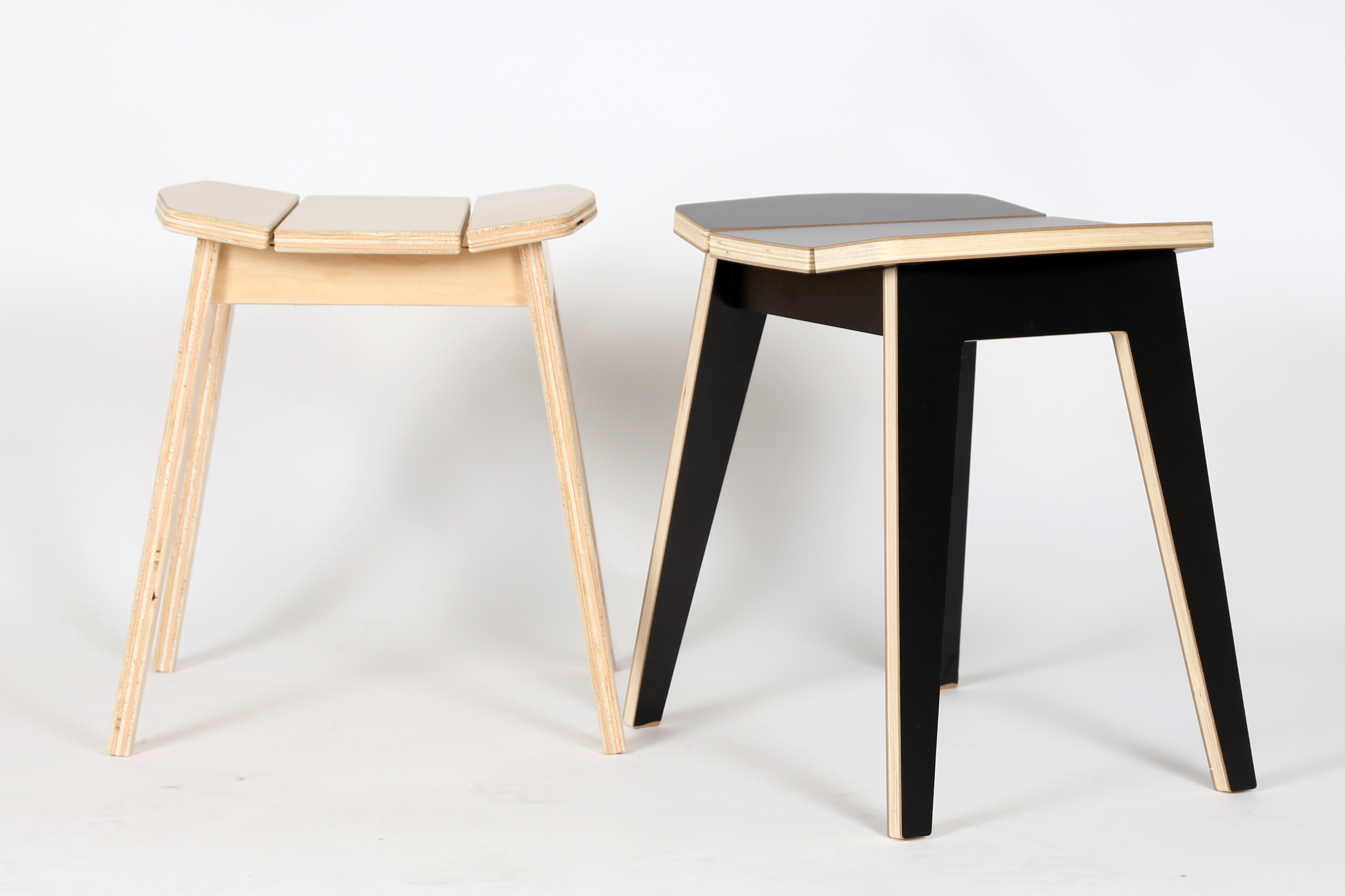
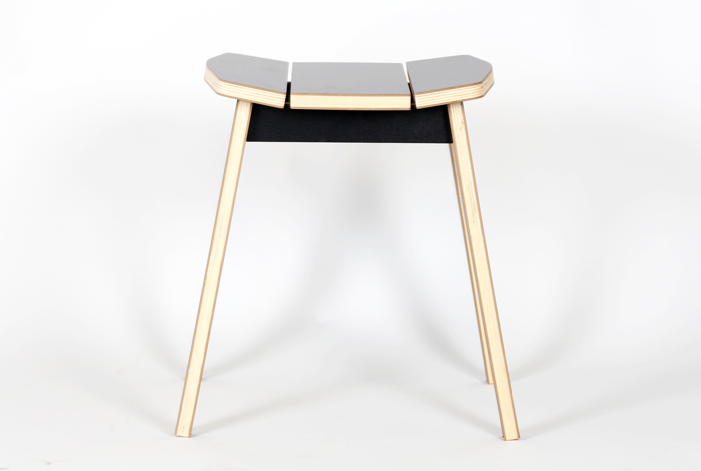
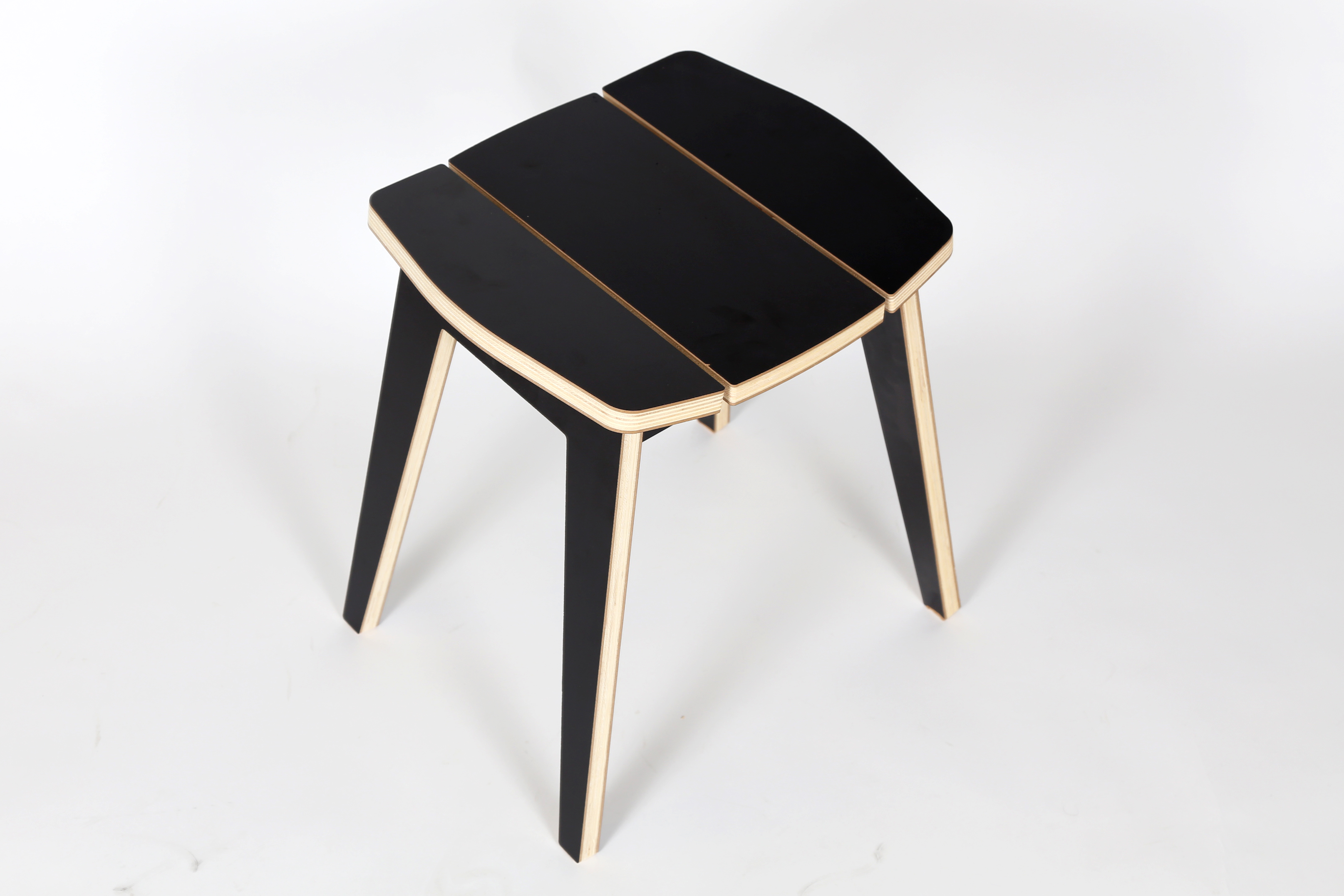
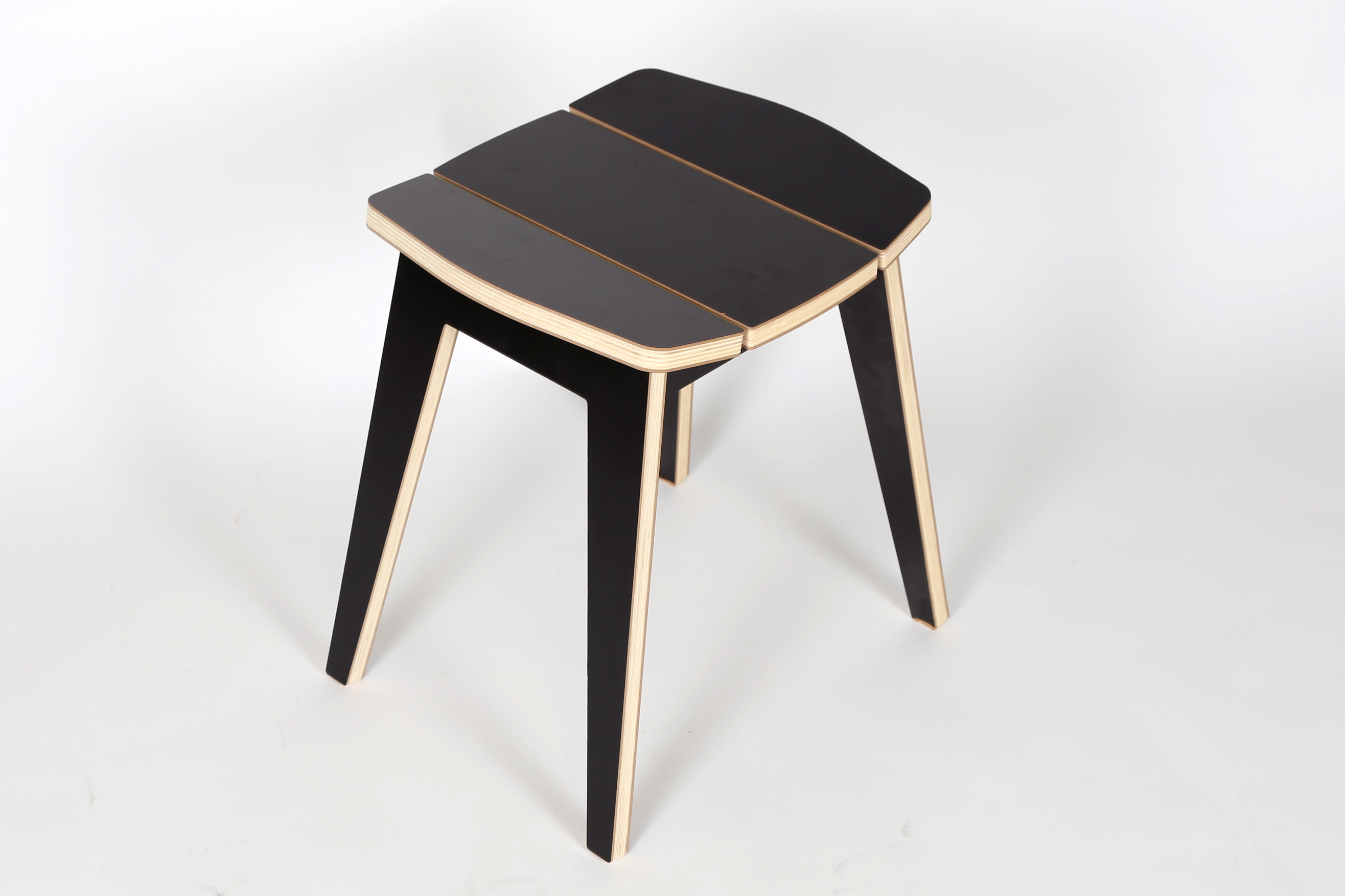
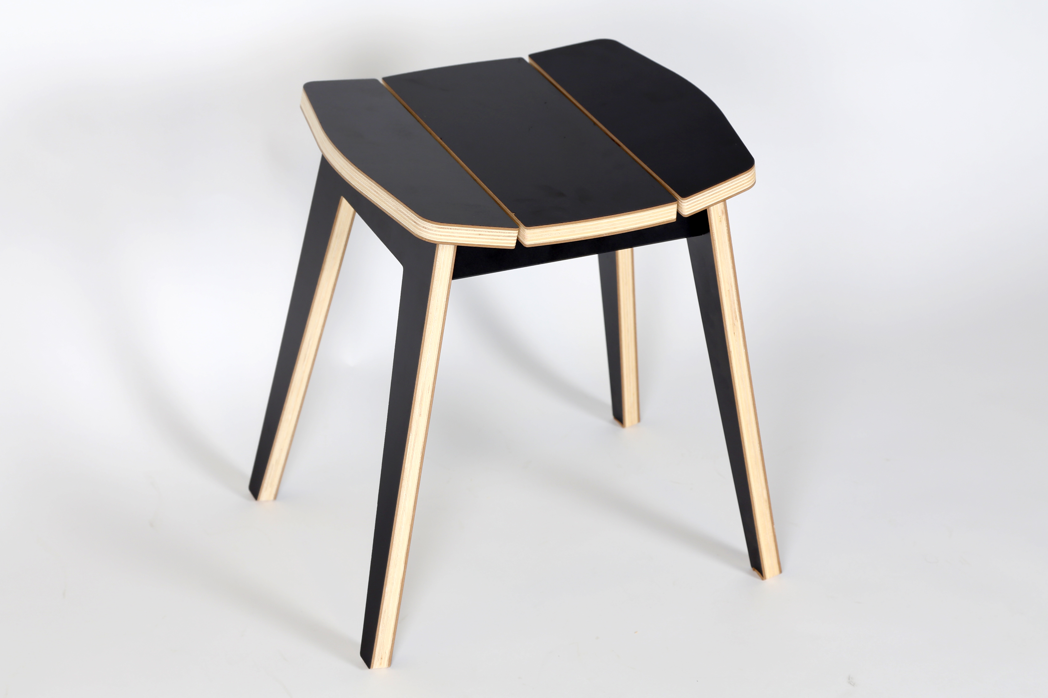
Now it's time to sit down, relax and enjoy your P9S Stool!
Assemble Another One!
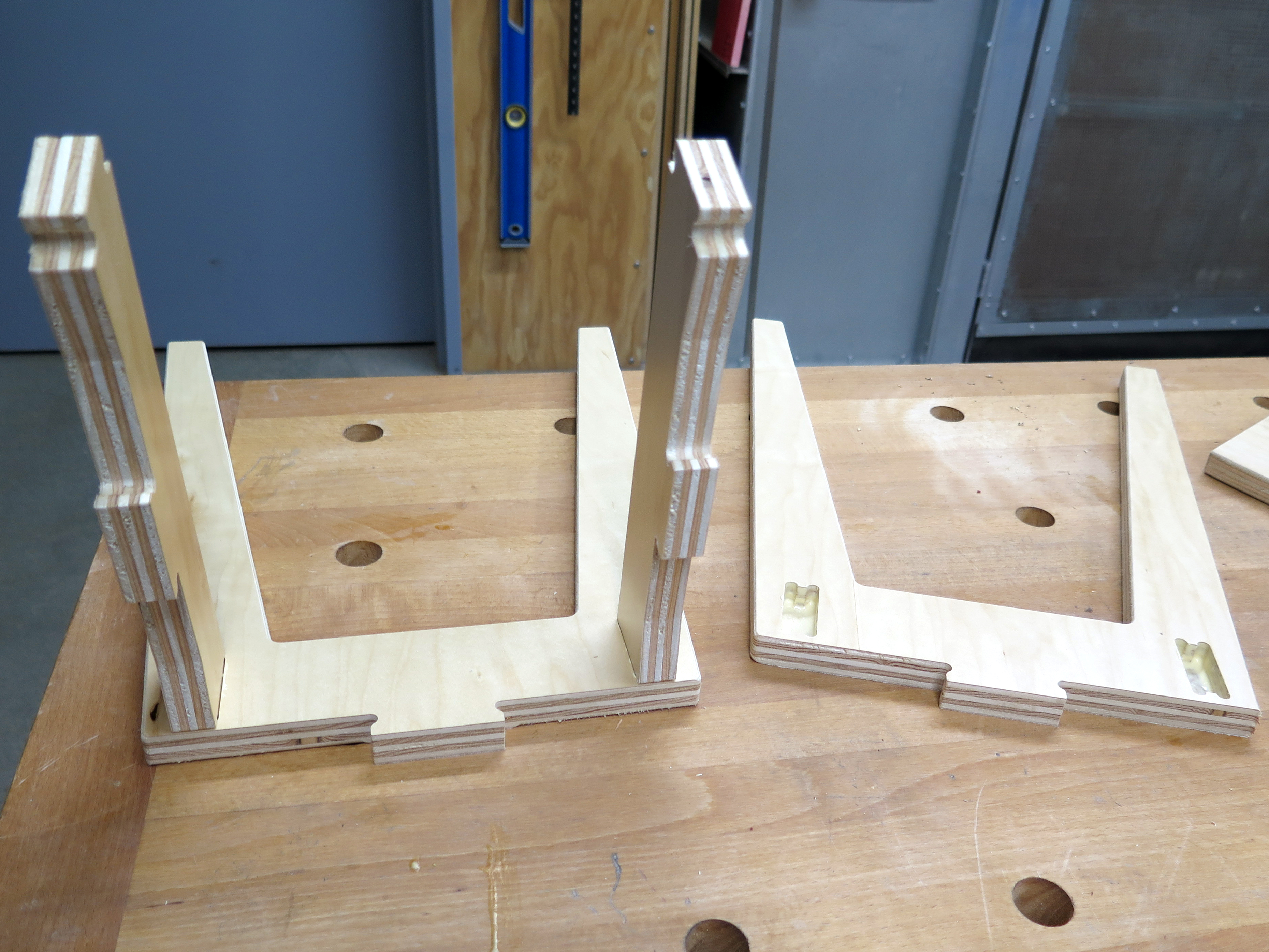
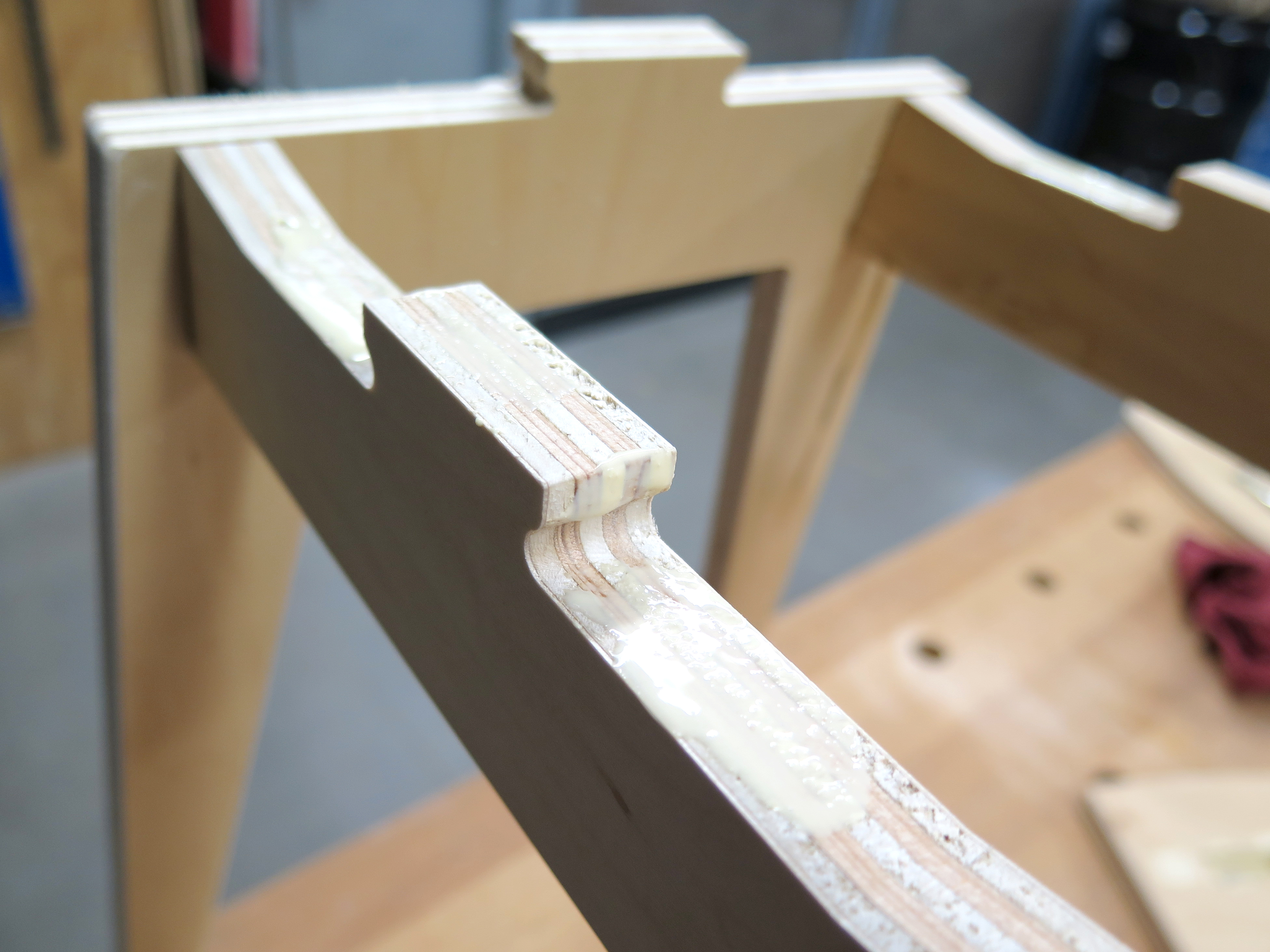
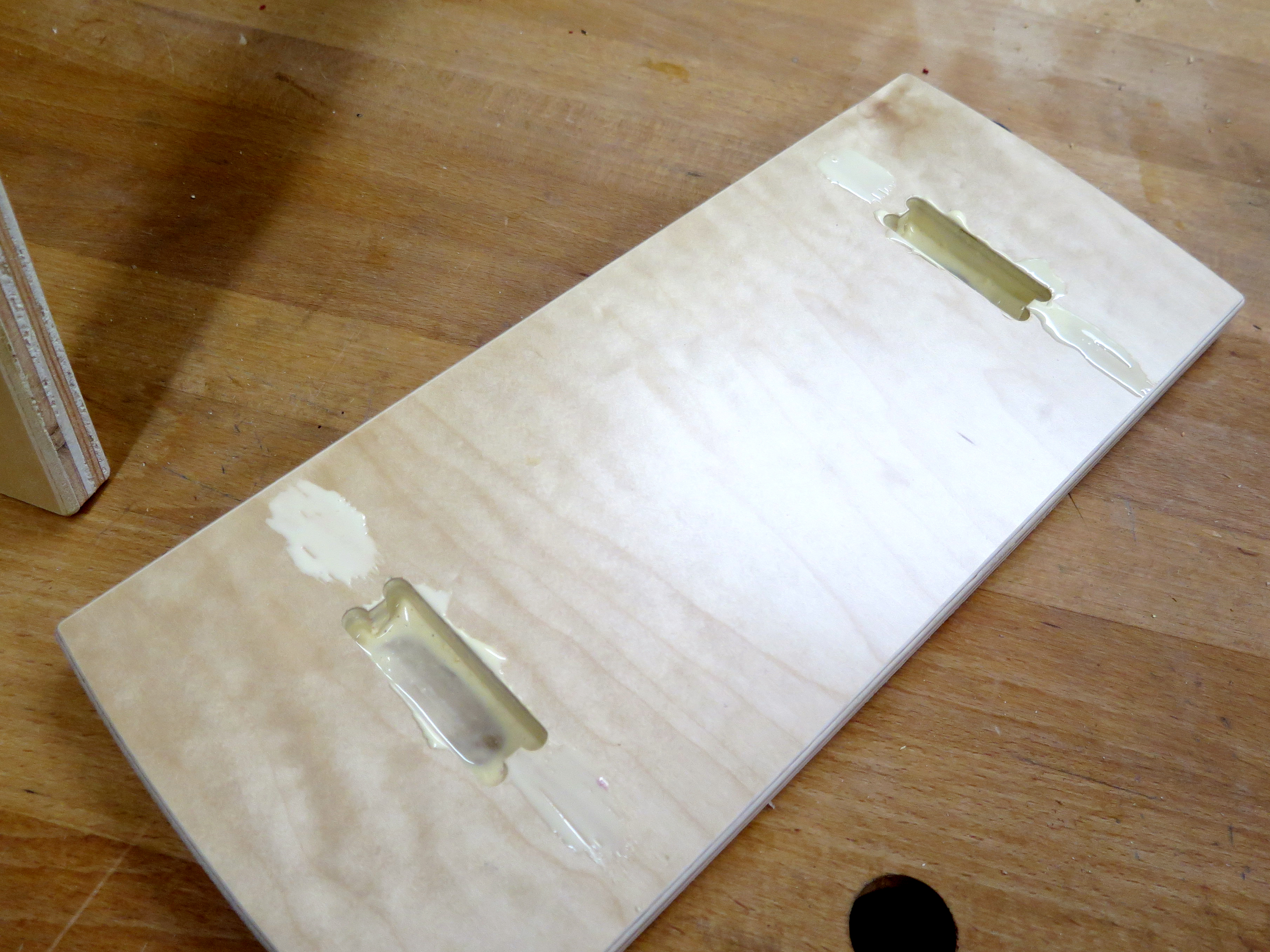
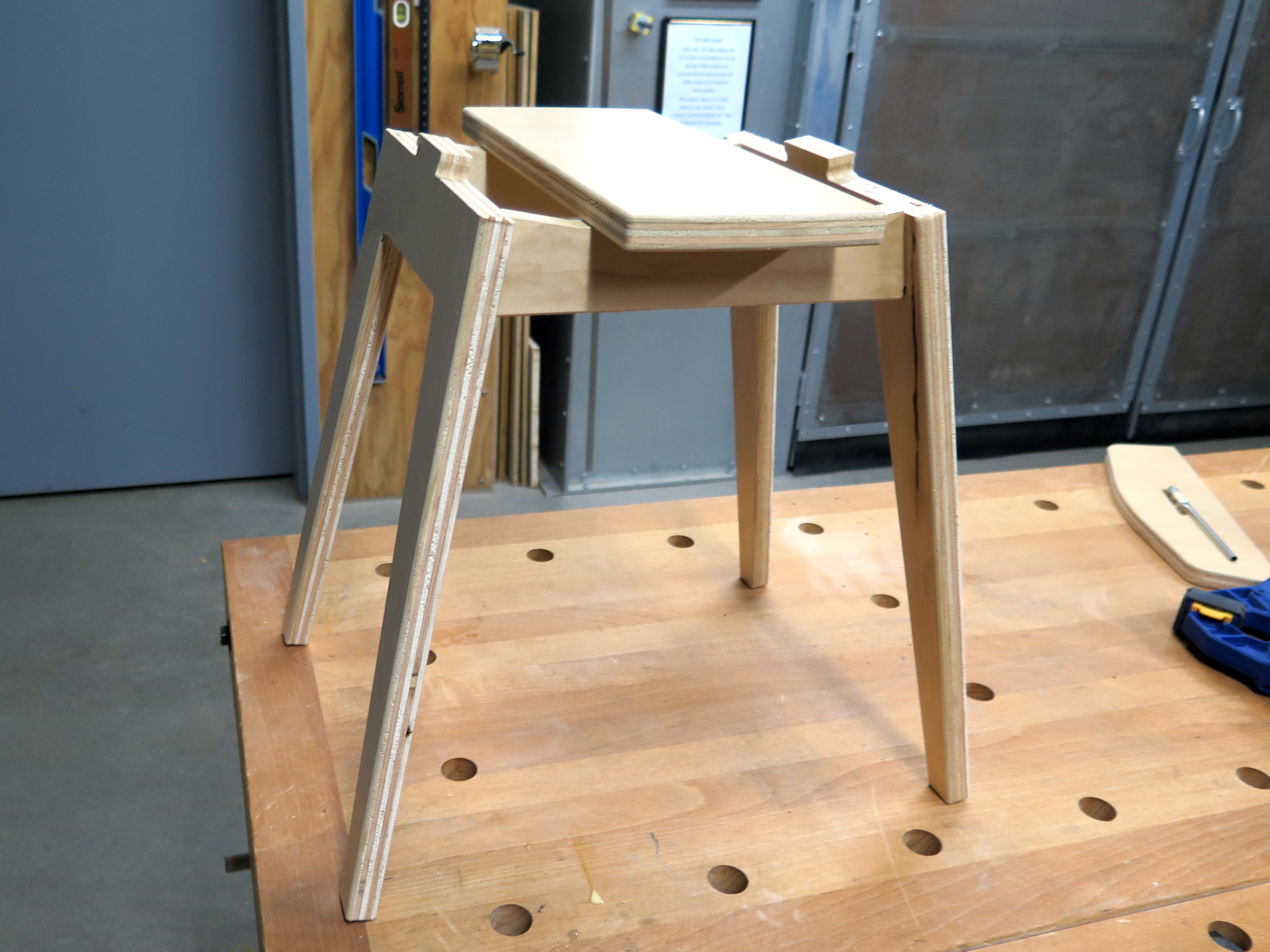
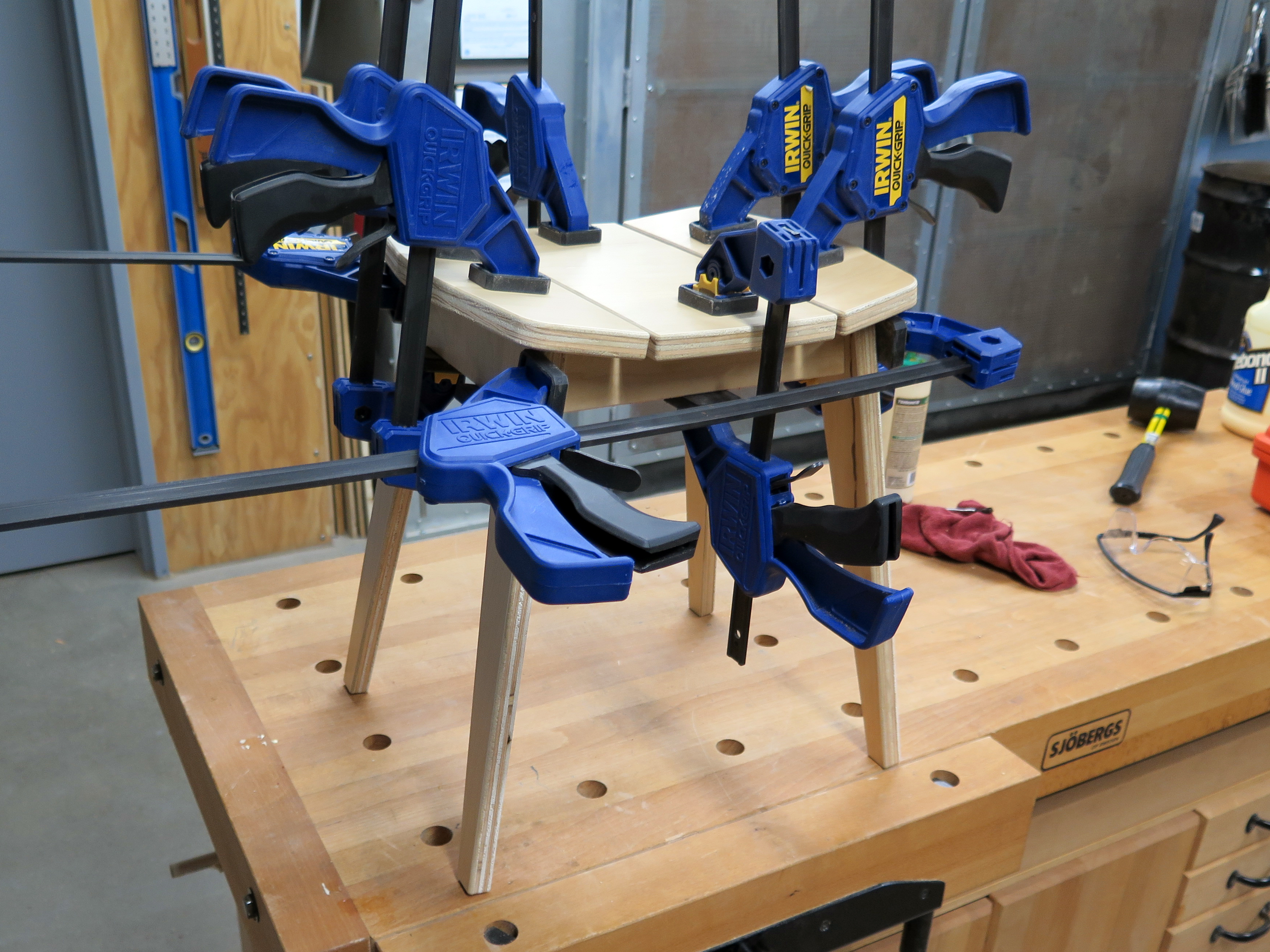
I decided to make a second one to go as an ottoman for my P9L Lounge Chair. I included some photos to show the assembly and clamping.
P9S Stool As an Ottoman
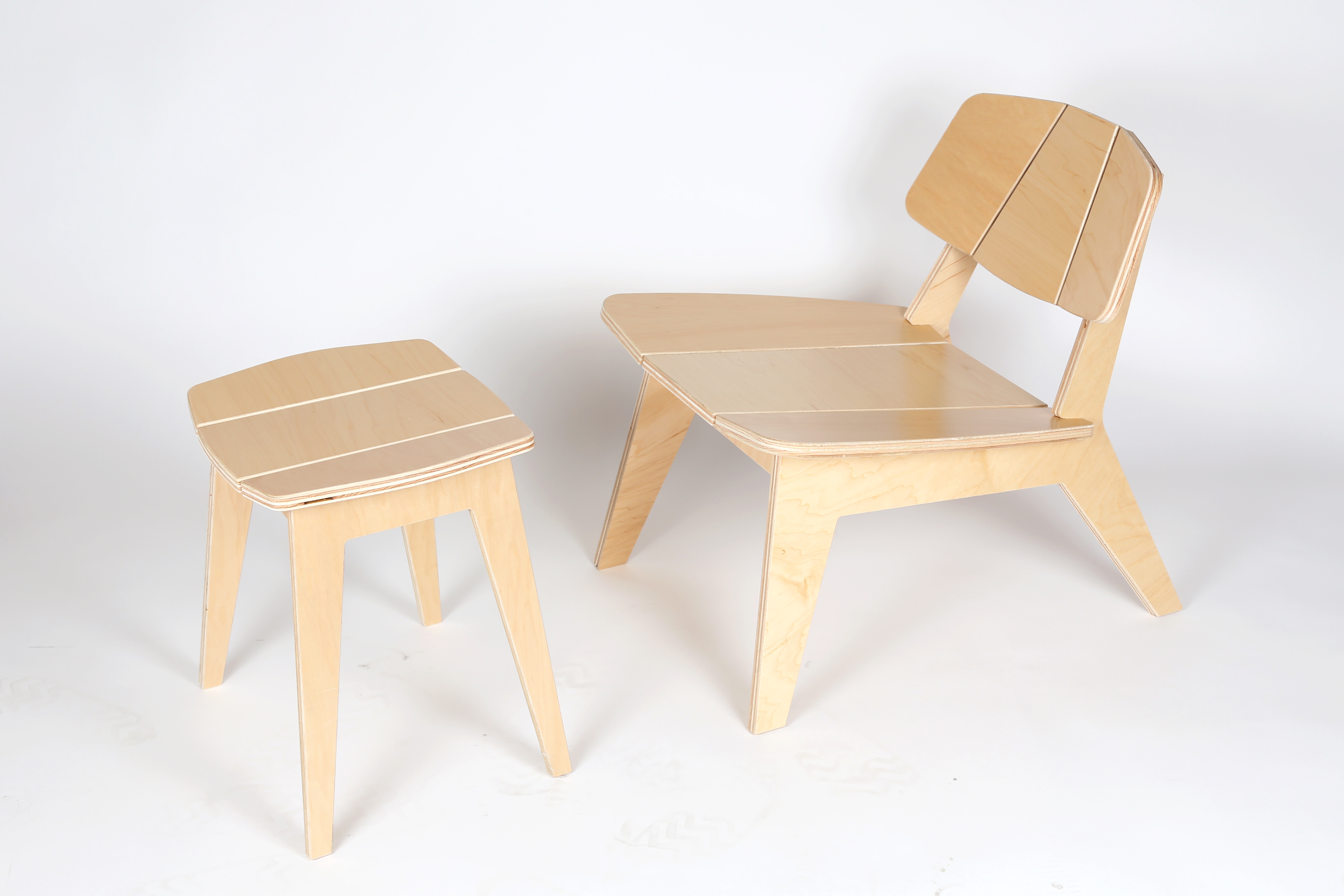
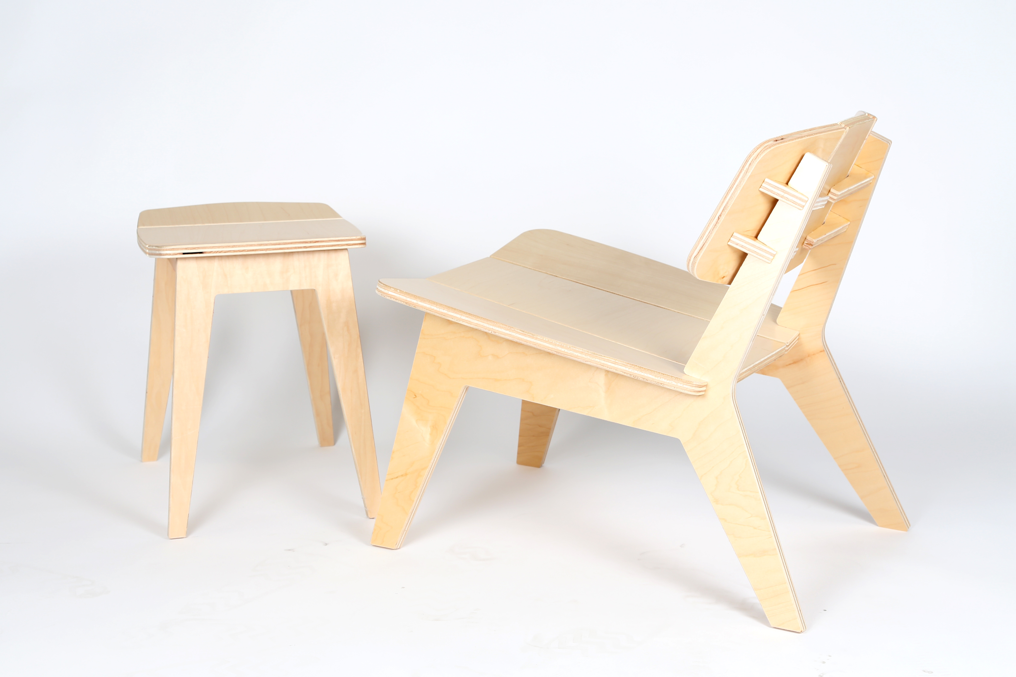
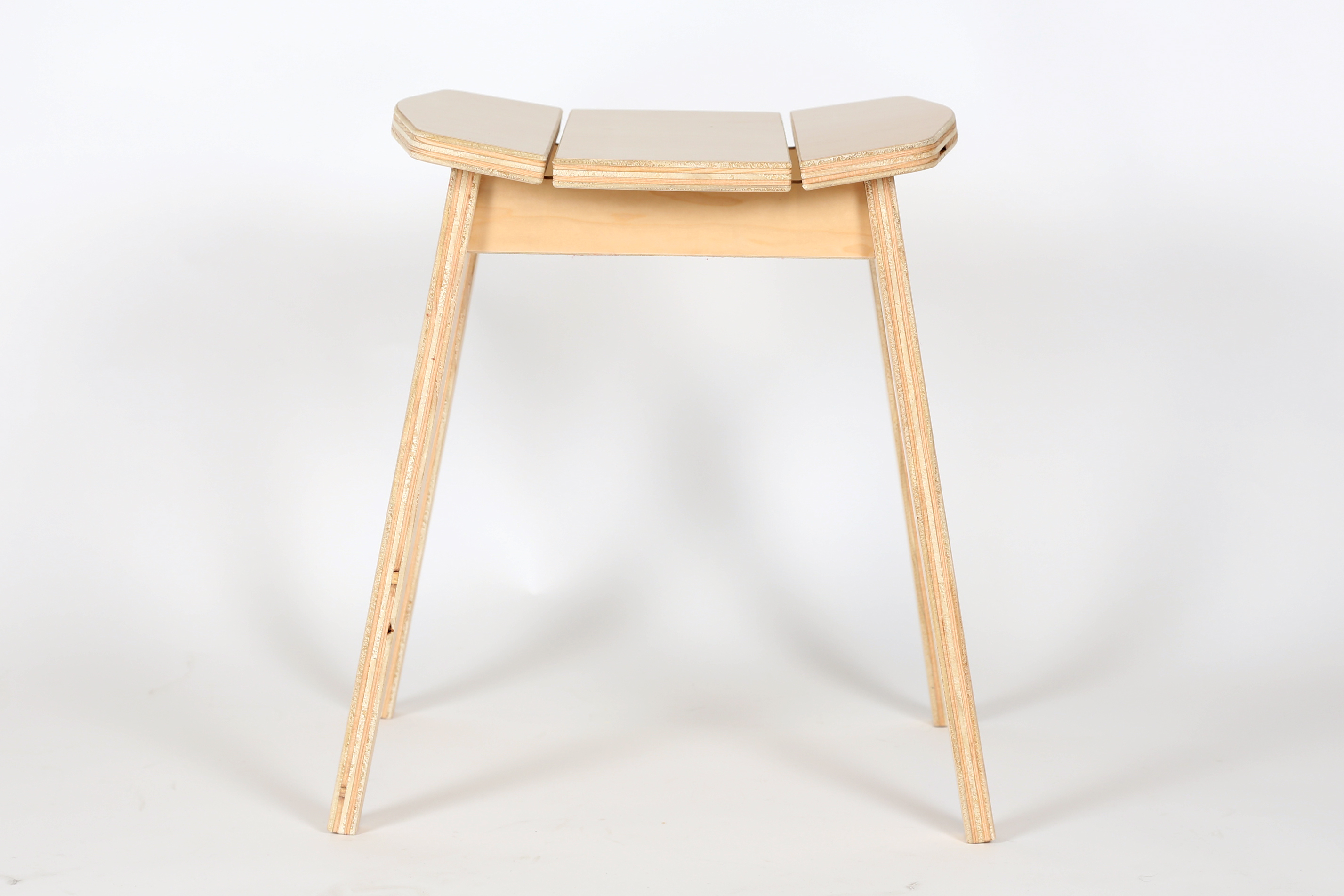
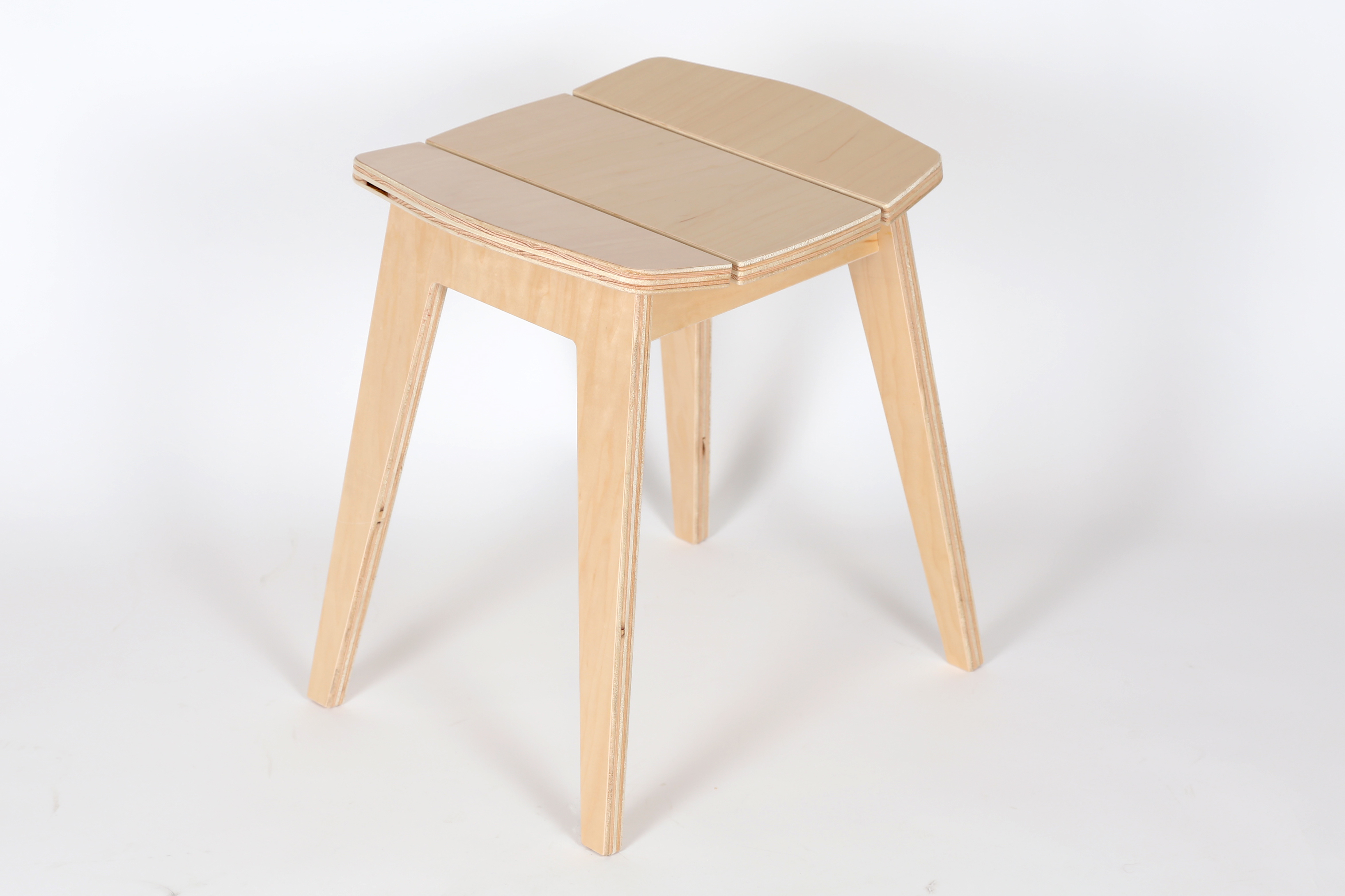
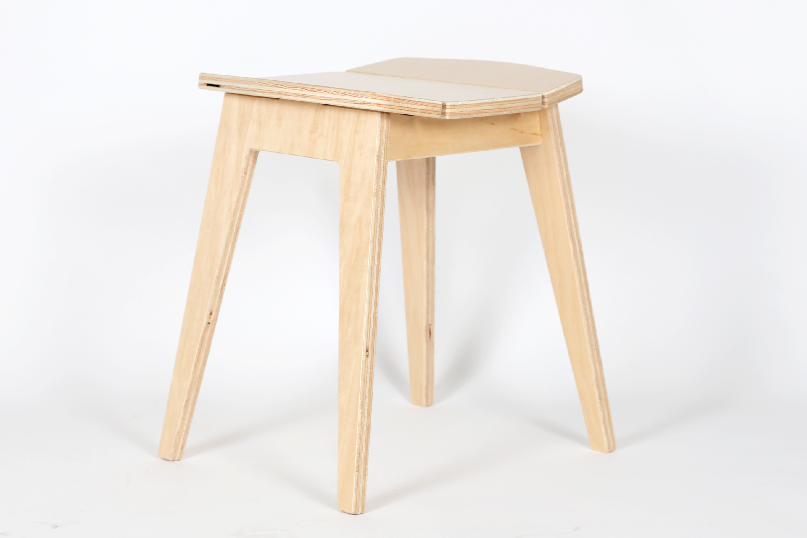
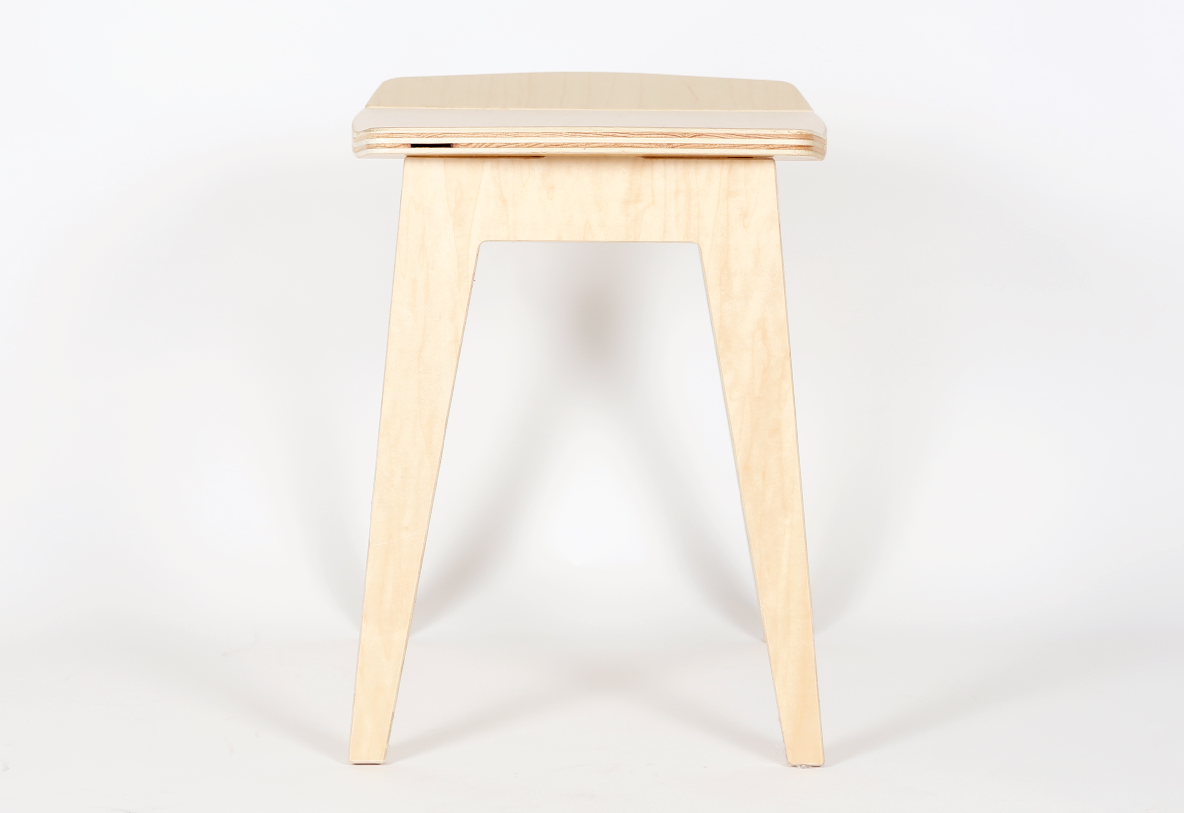
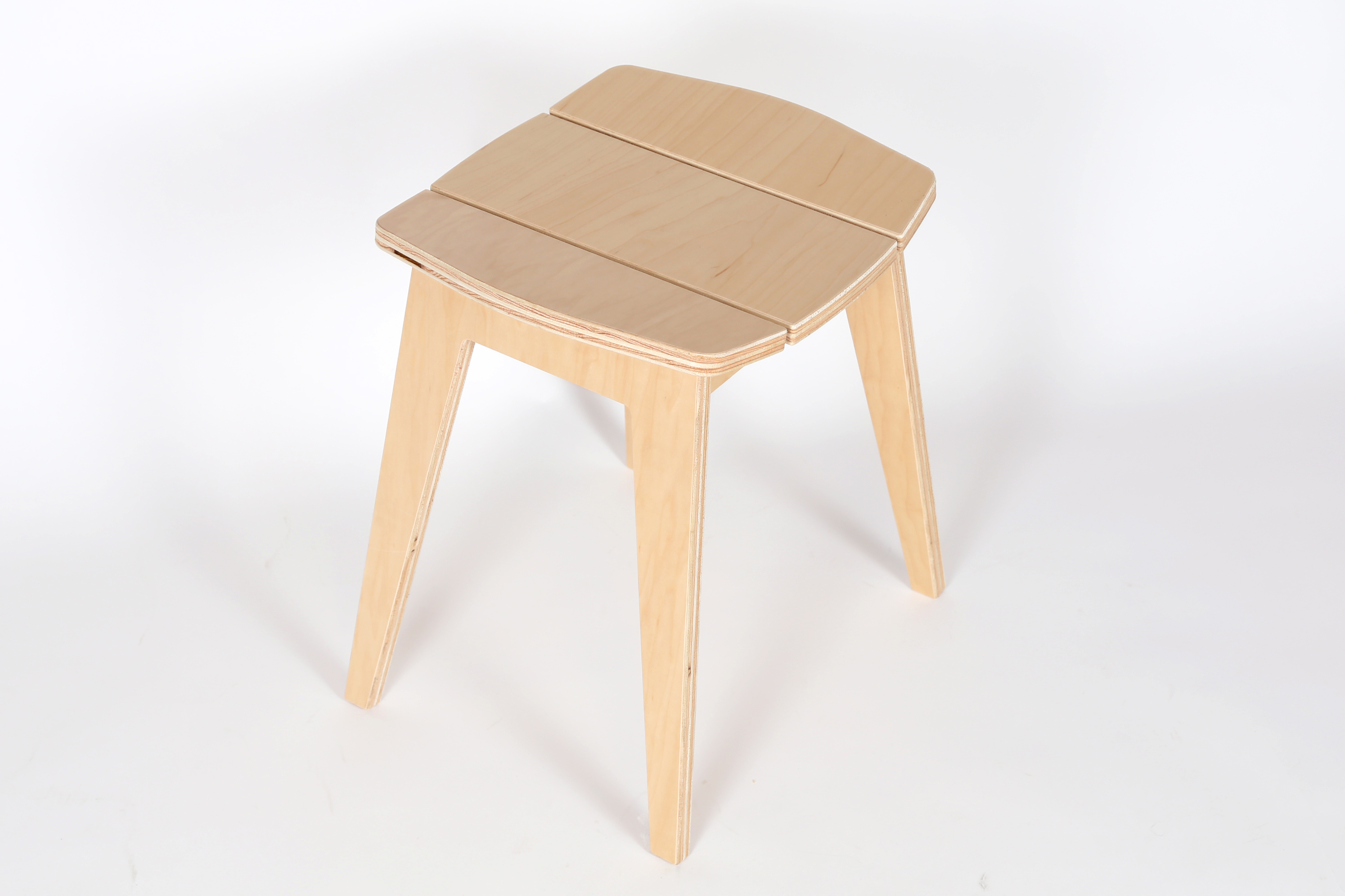
Here is the stool in pre-finished maple plywood as an ottoman for the P9L Lounge Chair. Check out the Dining Chair and complete your set.