P5 LED Panel With Raspberry Pi
by TomHammond in Circuits > LEDs
31005 Views, 101 Favorites, 0 Comments
P5 LED Panel With Raspberry Pi


Instructions last updated 11-3-2020
"Colossus Micro" is an animated light display in a portable size. It uses a "P5" LED panel that is controlled by a Raspberry Pi Zero W. Here are its features:
- Convenient size (12 x 6")
- Full color, high resolution LED display (2,048 pixels)
- Great for a tabletop display for trade/craft shows, displaying eye catching information, and anywhere that benefits from a bright, colorful display
- Wifi controllable from your smart phone or laptop (built-in wifi "hotspot")
- Battery powered using an internal rechargeable battery (also runs from a wall outlet)
- Displays static text/graphics, moving text, and animations
- Animations and graphics created on your laptop/computer with xLights, then uploaded wirelessly to the display
- Self contained (via included mounting bracket and cover)
- Easy to assemble (minimal soldering)
P5 panels are a good way to get into the world of LEDs and pixels. They are easy to setup and instantly rewarding; you can display anything on them including text, animations, and video.
A P5 panel has multi-color LEDs arranged in a grid on a rectangular base. There are three LEDs per "pixel", the colors mixing together to form a single color of light. The "5" in P5 means that pixels are spaced 5mm apart. So, in a typical 12" x 6" panel, there are 64 pixels across by 32 pixels down, totaling 2,048 pixels! That's plenty of pixels for text and animations. There are also P10 panels with 10mm pixel spacing which is better for outdoor displays.
These instructions are suited for P5 panels. You can buy them here. When choosing a panel, make sure that it is P5 and supports a 1/16 scan rate. Here and here are great introductions to panels.
The panel is controlled with a Raspberry Pi Zero, a low-cost microcomputer. A Raspberry Pi Zero can control up to four P5 panels, though this project only uses one panel.
The Raspberry Pi Zero will use a free program called Falcon Player to play animations on your display. Animations are created with a free program called xLights on your desktop or laptop computer. You create animations on xLights, save them to Falcon Player on your controller, then your display can run the animations without needing your computer. Your display will also be wireless; you can control it with your laptop or smartphone!
These instructions will teach you how to build a single panel display. The single panel display is self-contained, suitable for portability on a tabletop. Plans for a 3D printed case are provided.
Let's get started!
Stuff You'll Need to Buy


P5 Panel(s)
You can find these on Amazon and eBay; I bought mine from here. When choosing a panel, make sure that it is P5 and supports a 1/16 scan rate. If you buy them from someone else, make sure that they have six screw holes on the back (four in each corner, and two in the top middle and top bottom). This way the included 3D printed plans will fit your panel.
Note: These instructions are for P5 panels, I haven't not tested these instructions with P10 panels. I think that P10 panels have different screw hole spacing, so my provided 3D printed plans probably will not fit.
When ordering the panels, make sure that they come with power cables and data ribbon cables. You will need one power cable and a short data ribbon cable (12" or shorter is fine).
Controller
For the single panel display, go with a Raspberry Pi Zero W. These can be found here. Make sure you get the "W" or wireless version. It needs to have a 40-pin header on it with male pins sticking up. Either the Raspberry Pi Zero W will come with this header soldered on or you will need to solder it yourself.
Note: In these instructions, Raspberry Pi Zero W will be referenced as "RPi".
Panel Controller "Hat"
A "hat" is a circuit board that attaches to the top of the RPi. The panel then connects to the hat via ribbon cable(s). Buy this controller.
Boost converter
Although the battery is rated to deliver 5.1V of power, its output can drop to as low as 4.4V when powering the display. This can case the Raspberry Pi to stop functioning. By connecting a boost converter between the power source and the RPi, it will ensure it receives 5.1V no matter what the battery's output is. You can buy these here.
Power Supply
For a one-panel display, buy a 5 volt, 2.5 amp power supply with a micro USB connector, like this one.
Terminal Block (8 terminal) (buy two)
This is used to distribute power from the power supply to the controller and P5 panel. An eight-terminal block will do (four pairs of connections). This terminal block will work. To make sure that you buy the correct size, each terminal should be roughly 9mm wide.
A second terminal block is used to connect the pushbutton to the panel hat.
Terminal Barrier Strip
This electrically connects terminals on the terminal block. Buy a four-position barrier, then cut it in half, making two two-position barriers. You can buy barrier strips here.
Red "Fork" Connectors
These are crimped onto each end of the power & ground cables, making them easy to attach to the terminal black and/or power supply. Make sure that you buy the correct "width" of fork connectors that will fit the terminal block and power supply. SV1.25-3.2 is the correct width. You'll need 11 of them.
Power wire
You'll need short lengths of 18AWG wire for the power & ground lines that connect the power supply to the terminal block.
Nuts, Bolts, Washers
For the single panel display, you'll need (31) 10mm M3 bolts and (18) M3 nuts to assemble the 3D printed frame and cover that attaches to the P5 panel. You will also need six washers for the corner bolts that attach the 3D printed frame halves to the panel. You can easily find these on eBay or your local hardware store.
3D Printed Parts
If you are building a single panel display, please 3D print the panel bracket and back cover here.
Red "Spade" socket connectors
These are crimping wires onto the power switch. 22-16 is the correct width. You'll need four of them.
LED and 270-ohm resistor (1/4 watt)
This will be used for the "power on" light. The LED light can be any color, but make sure that the diameter is 5mm.
Micro USB Panel Mount Connector
This will attach to the back cover, allowing power to get from the micro USB power supply to inside the panel.
Portable Charger/Power Bank
This power bank allows the single panel display to be battery powered as well as run from a wall outlet. This power bank has 10,000 mAh capacity, allowing the display to operate for at least five hours, possibly more.
This particular power bank allowing discharging during charging, which allows the display to operate while the battery is being charged.
It also has 5.1+V output (not merely 5V) which is important as voltage can drop during discharge, preventing the controller from crashing due to sporadic low voltage. It's important to supply at least 4.75V to the RPi.
It is also small enough and the proper size to fit inside the 3D printed enclosure.
Finally, this particular battery automatically turns "on" and provides power when something is plugged into it. This way, the external switch (below) can be used to connect the panel and controller to the battery, turning the battery "on" when the external switch is flipped. This is important as the battery's own manual power button is not accessible from within the enclosure.
Power switch
This switch is attached to the 3D printed enclosure for the single-panel display. It is DPST, which means that the both sets of power and ground wires are enabled/disabled when the switch is flipped. You can buy the switch here. The hole for the switch on the 3D printed enclosure is 20 x 13.5mm, so make sure the switch that you buy fits this hole. Because of inaccuracies in 3D printing, a switch that fits a mounting hole of 19 x 12.5mm should fit perfectly.
Pushbutton
This is used to change animations on the panel. You can also use your smartphone/laptop via wifi to change animations, but the button serves as a simpler method. The hole for the button is 8.5mm in diameter, so make sure that the button you buy fits this hole (an button with a 8mm mounting hole should work best, like this one).
Resistors for pushbutton (1/4 watt)
To interface the button with the RPi, you'll need one 10K resistor and one 1K resistor. You'll also need fine wire that will connect a few points on the RPi hat to the pushbutton and resistors.
USB cable
You'll need a USB cable with a type "A" male connector on one end. Because this cable will provide power to the P5 panel, its wires must be a higher gauge than a typical USB cable. Use the thickest USB cable that you can find. A USB cable meant for charging is a good pick, too.
Instead of trying to find a thick USB cable, it was easier to build my own cable. Buy this USB connector, then solder power and ground wires to it using this diagram. Then you'll know for sure that the cable is thick enough to handle the amp load to the panel and battery.
16 gigabyte microSD memory card
This card will contain the software (Falcon Player) that the RPi will use to control the LCD panel. Make sure the memory card is "class 10" or higher. Lower classes operate too slowly. On a 16 gigabyte memory card, Falcon Player will use about 6-7 gigabytes, leaving 13-14 gigabytes free for your own animations and videos.
Handle
In order to carry the display around without handling the LCD side of the panel, purchase a handle that will be bolted onto the side of the display. The bolts should be 76mm apart (from their centers).
Wire ties
Have five 4" wire ties on-hand to organize the wires after the display is assembled.
Charge the Battery


If you are building a single panel display, now is a good time to charge the battery. Plug the battery into the micro USB power supply, then plug the power supply into a wall outlet. That way, your battery is charging while you build the display from the rest of these instructions.
Stuff to Help With Building


This equipment will certainly come-in handy while you are building your Colossus Micro:
- Phillips screwdriver
- Flat screwdriver (narrow blade)
- Hammer
- Screwdriver to match the M3 bolts that you have
- Crimper (for the fork connectors)
- Heat shrink tubing
- Heat gun, blow dryer, cigarette lighter, or stick lighter (to melt heat shrink tubing)
- Jumper wires with alligator clips (useful for troubleshooting problems)
- Soldering gun/iron & solder (especially a soldering iron for soldering components onto a circuit board)
- Electrical tape
- Craft/utility knife
- Wire cutters
- Wire stripper
- Voltmeter
- Magnifying glass
- Super glue
- Cardboard or towel to rest the P5 panel on
- Small, adjustable wrench
- Foam tape (only a small piece is needed as a spacer between the Pi Hat and the terminal block below it)
Assemble Frame


VIDEO INSTRUCTIONS:
.
There is a 3D printed enclosure that converts a single P5 panel into an enclosed display complete with mounts for the controller and related hardware. Click here for a 3D view of the enclosure with all of its parts attached.
.
Download and 3D print the enclosure parts here. There are eight parts: left-side panel bracket, right-side panel bracket, controller sled, terminal block sled, boost converter sled, battery holder, left-side cover, and right-side cover. Print with at least 40% infill for strength, except for the cover which can be printed with 10% infill.
Some of the parts print best with customized supports. If you are using Cura, use the "support blocker" feature. Here are the support recommendations for each part:
Left-side panel bracket (battery side): Print with no supports. If you enable supports, plastic will fill the nut holes with are difficult to remove.
Right-side bracket (controller side): Print with supports, but block supports for the slots where nuts will slide in, the micro USB hole, and LED hole. Allow supports for the switch hole and button hole.
Terminal block sled: Print with supports, but block supports for the nut slots (middle of the sled).
Battery holder: Print vertically with no supports.
Boost converter sled: Print flat with supports, but block supports in the center of the sled so that the four tiny clips in the main cavity do not have supports under them.
Controller sled: Print with supports.
Left-side and right-side covers: Print battery side cover with no supports, print RPi side cover with supports. Attached to this step are PDF files that you can print on 8-1/2 x 11" Avery label paper, making stickers for the back cover that instruct people how to use the panel.
RPi spacers: Print four of these without supports. Scale them 5-10% larger to slide easily on the bolt, not stick to it.
Attach left and right-side panel brackets to P5 panel (gray in the attached diagram)
Flip the P5 panel face-down onto a soft surface. A towel or piece of cardboard will do. Now you are looking at the back of the panel. Rotate the panel so that the large "arrow" is pointing down. The "left side" of the back of the P5 panel has the four-pin power connector and is where the battery will attach. The "right ride" of the panel has the downward arrow and is where the RPi will be attached.
Insert five M3 nuts into the left-side (battery) panel bracket and six M3 nuts into the right-side (controller) panel bracket's nut slots. Place six washers on the panel bracket hole slots (four corners and two in the middle), then attach both brackets onto the LED panel with six M3 bolts. Do not tighten bolts until the six bolts are inserted, then tighten them all.
Note: The M3 nuts can be difficult to insert into the nut slots. You can carefully push them in with a flat-blade screwdriver and/or tap them in with a hammer, but be careful that the tools do not slip and you harm yourself.
Assemble controller sled (black in the attached diagram)
Push four M3 nuts into the sockets in the flat area of the controller sled. Make sure they are fully seated all of the way in. Placing a screwdriver on the nut, then gently tapping with the hammer helps.
Start four M3 bolts into the RPi's corners. The bolts barely fit; screw them in slowly, barely protruding from the RPi bottom. Place the RPi on top of the four M3 nuts. Tighten the bolts just enough to reach the nuts; the bolt heads will not be flush with the RPi when finished.
Alternatively, tighten the bolts to extend 5mm past bottom of RPi. Insert 3D printed spacers between RPi and controller sled, then tightening the bolts just enough to reach the nuts. This alternate method allows the Pi Hat to hover higher over the terminal block on the same sled, ensuring that the hat's circuitry doesn't touch the block.
Insert four M3 nuts into the side slots in the right-side panel bracket. Make sure the nuts are inserted so that their holes are fully visible from the perpendicular side.
The controller sled also supports a terminal block which is used to connect the button circuitry. Place a terminal block on the controller sled, then secure with two M3 bolts. Make sure that the bolt ends are flush with the bottom of the sled (slightly recessed inside is better).
Place the controller sled on the right-side bracket, then attach to the bracket using four M3 bolts.
Assemble terminal block sled (red in the attached diagram)
Insert two M3 nuts in the middle sides of the sled.
Place the terminal block on the sled, then fasten with two M3 bolts.
Place the sled on the left-side panel bracket, then secure with two M3 bolts.
Attach battery holder (green in the attached diagram)
Attach the battery holder to the left-side bracket with two M3 bolts. The two large holes in the battery holder will fit into the large, round nubs on the terminal block sled.
Attach boost converter sled
Attach the boost converter sled in a vertical position, to the left of the power terminal block sled. The vertical lip of the sled rests against the battery sled, and the horizontal lid at the other end of the boost converter sled rests on the panel frame. Use foam tape to attach both lips. Do not insert the boost converted into the sled yet.
You're done with the single panel enclosure!
Wiring the Components


VIDEO INSTRUCTIONS:
.
Take a look at the attached wiring diagram.
Power is provided to the battery's "input" via the micro USB panel-mount connector. The battery's "output" then connects to the power switch. This switch allows the display to be turned on and off, but allows the battery to be charged even with the display off. The switch is then connected to the terminal block which provides power to the P5 panel, RPi, and power LED.
Note: Do not connect the USB "output" of the battery to anything until all of the wiring is complete! This will prevent damaging components from accidental power.
Connect micro USB panel mount cable
Attach the micro USB panel mount cable to the right-side panel bracket using two M3 bolts. Leave the end of the cable disconnected for the time being.
Note: Your panel mount cable's bolt holes may have raised rubber ears. When bolting the mount cable to the frame, the micro USB socket will recede further into the bracket, making it slightly difficult to use. You can carefully shave these rubber ears flush so that the face of the socket is flush as it interfaces with the LCD bracket. A Dremel tool or craft knife works well for this.
Attach terminal barrier strips
If you have a four-position terminal barrier strip, cut it in-half so that you have two, two-position strips. Attach one strip to positions 1 & 2 on the terminal block, and the other strip on positions 3 & 4. This way, the power and ground coming from the switch is distributed to positions 1, 2, 5, 6 (GND) and positions 3, 4, 7, 8 (5V) on the terminal block.
Prepare USB cable
This cable is used to output power from the battery to the switch. Do not connect the cable to the battery until later steps!
Look closely at the metal "tongue" of the USB connector. There are four troughs to which you can solder wires. Using the included USB pin-out diagram, solder red and black 18 AWG wires to the outer troughs (the inner troughs are not used). Snap the black top & bottom covers onto the metal connector, then use a cable tie to keep it closed. Check the polarity of your cable by plugging it into a computer. You should get +5V with a voltmeter. If you get -5V instead, open the connector and reverse/re-solder the cables. Lastly, connect spade connectors to the ends of the black & red wires.
Attach switch to terminal block
The power switch has four terminals. When the switch is flipped one way, all four terminals are not connected to each other. With the switch flipped the other way, two pairs of pins are connected to each other. This way, you can connect/disconnect the power and ground wires simultaneously with the flip of the switch. Use a voltmeter to determine which switch terminals connect and disconnect when the switch is flipped. Mark the terminals with pieces of tape so that you remember the pairs.
Insert the switch into the right-side panel bracket. It should snap into place in the largest rectangular hole.
Attach the USB cable spade connectors to the inputs of each terminal pair on the switch.
Crimp spade connectors onto the end of a black 18 AWG wire and a red 18 AWG wire. Attach these wires to the outputs of each terminal pair on the switch. Crimp fork connectors onto the other end of these wires, then attach to position 6 on the terminal block (black) and position 7 on the terminal block (red).
When you are finished, flipping the switch one way disconnects the power and ground output wires from the battery to the terminal block. Flipping the switch the other way allows the power and ground wires from the battery to reach the terminal block.
Attach P5 panel power to terminal block
Your P5 panel came with a power cable with a white plug on one end and red & black fork connectors on the other end. You will need to shorten this cable as it's too long. Cut the existing fork connectors off, then shorten the wires so that the white end reaches the white socket on the P5 panel and the other end of the cable reaches the terminal block.
Attach fork connectors to the red & black wires. Attach the black wire to position 2 on the terminal block and the red wire to position 3. Then, plug the white connector into the white socket on the P5 panel.
Attach RPi panel "hat"
The panel "hat" allows the RPi to communicate with the P5 panel. The hat sports a 40-pin female connector while the RPi has a matching 40-pin male connector. If your RPi doesn't have a male connector, you'll need to solder a connector on first.
Rotate the hat on top of the RPi so that it extends toward the power switch side of the frame. Carefully line-up the male & female 40-pin connectors, then push the hat onto the RPi, stacked like a sandwich.
If you didn't choose to raise the RPi with the 3D printed spacers, then wedge a piece of foam tape between the bottom of the Pi Hat and the top of the terminal block, sticky side up. This will protect the hat circuitry from touching the terminal block.
Prepare boost converter
The battery is rated for 5.1V output, but its voltage can drop to as low as 4.4V while the panel is running. This can cause the RPi to stop functioning. By connecting a boost converter between the power terminal block and the RPi panel "hat", it will ensure that the hat receives 5.1V no matter what voltage the battery is outputting.
Solder red and black 18AWG wires to the VIN+ and VIN- terminals on the boost converter accordingly. Attach fork connectors to the other ends of the wires, then attach to the power terminal block (position 4 for the red wire and position 1 for the black wire). Next, solder red and black wires to the OUT+ and OUT- terminals on the boost converter accordingly. Strip the other ends of these wires, leaving them bare for the moment.
Next, we need to set the boost converter for 5.1V output. This step is important, otherwise you can damage the converter! There is a tiny brass screw on the booster converter. Listening closely, turn the screw clockwise until you here a slight clicking sound. Then turn the screw counterclockwise six turns.
Connect a voltmeter to the bare ends of the wires on the boost converter's outputs, configuring the voltmeter to read DC voltage. Connect the USB cable to the battery. This will allow power to flow from the battery to the power terminal block. Read the voltage displayed on the voltmeter. Turn the screw in either direction until it reads 5.1V. Do not set the voltage any higher, otherwise you could damage the RPi!
When the voltage is set correctly, disconnect the voltmeter and the USB cable from the battery. Carefully Insert then boost converter into its sled. If you have difficulty with this, shave-off a bit of the clips in the cavity of this sled.
Lastly, insert the red wire from the OUT+ terminal of the boost converter to the green "+5VDC" terminal on the RPi panel "hat", then tighten the connection with a small flatblade screwdriver. Similarly, insert the black wire from the OUT+ terminal to the "0V" terminal on the hat.
Connect RPi panel "hat" to boost converter
The hat has a green two-position terminal with "+5VDC" and "0V" labels. With the red OUT+ wire coming from the boost converter, twist the bare strands together, then insert into the "+5VDC" position on this green terminal. Do the same with a black OUT- wire, inserting it in to the "0V" terminal.
Attach power LED
This LED lights when the P5 panel and RPi is "on" and running via the power switch. With the switch turned off, the panel and RPi turns off. If the panel is plugged into DC power via the micro USB power supply, the battery will continue to charge even when the panel is turned off via the switch.
The LED has leads, the longer of which is the "positive" pin. The shorter lead is the "negative" pin. The negative lead is also identified with the LED having a "flat" side (see attached picture).
Trim the 270-ohm leads to 2/3 their length. Solder one end of the resistor to the positive lead on the LED. Solder a red wire to the other end of the resistor. Trim the red wire's length so that the LED will reach from the right side of the panel bracket to the terminal block. Slip heat shrink tubing over the wire, enough from the LED bulb's base to the beginning of the red wire. Heat the tubing to seal it. On the other end of the red wire, attach a fork connector, then attach to position 8 on the terminal block.
In the same way, attach a black wire to the short lead on the LED, add heat shrink tubing and fork connector, then attach it to position 5 on the terminal block.
Add super glue around the diameter of the LED base, then push the LED firmly into the small hole on the right-side panel bracket (next to the power switch).
Attach panel ribbon (data) cable
Your P5 panel cable with a 16-pin (2x8 header) ribbon cable. Connect one end to "CN1" connector on the RPi "hat" and the other end to the "JIN1" (input) socket on the P5 panel.
Note: The P5 panel has two 2x8 sockets, use the socket near the RPi (not the socket near the battery).
Connect button
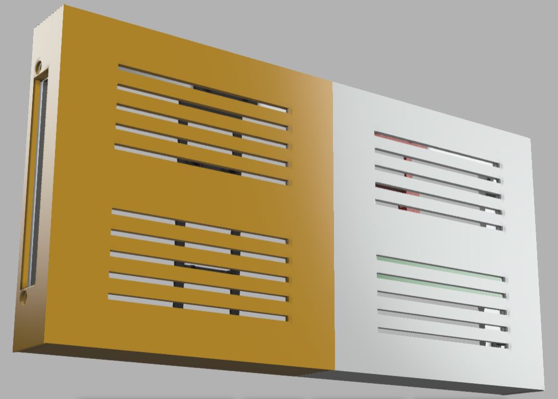
Attach fork connectors to a thin red wire, black wire, and third wire of another color (I used brown). Attach these to one side of the RPi sled's terminal block with the brown wire in the middle. On the other side of the terminal block, attach the 10K resistor between the red and brown terminals, then attach the 1K resistor between the black and brown terminals. This way, the resistors are connected in the middle. See the attached photo with the wires highlighted.
Note: See attached pinout of the RPi as a reference to locate pin numbers. You are not soldering to the RPi, but to the top of the panel hat's 40-pin connector with the exposed soldering points.
Solder the opposite end of the red wire to pin 1 on top of the panel hat. This will provide 3.3V from the panel hat to the button. A magnifying glass and a steady hand is best for this delicate operation. Be very careful that solder nor the wire touches the other soldering points on the hat!
Note: Do not connect the red wire to 5V green terminal on the panel hat! This could damage the RPi as its GPIO pins expect 3.3V. Connect the red wire to pin 1 on the panel hat as it's a 3.3V power source.
Solder the opposite end of the black wire to a terminal on the button. Solder a different black wire to the other button terminal, then solder the opposite end of this wire to pin 39 on the panel hat (0V).
Lastly, solder the opposite end of the brown wire to pin 37 on the panel hat. Again, refer to the attached wiring diagram to check your work.
When you are finished with wiring, it should match the attached diagram and all eight positions on the terminal block should have a wire attached to it. Congratulations!
Downloads
Install Falcon Player on Memory Card


VIDEO INSTRUCTIONS:
.
The RPi does not come with software on it. To do this, it is necessary to install software (Falcon Player) onto a memory card, then insert the card into the RPi. When the RPi is then turned on, it loads Falcon Player and is ready to use.
Prepare the memory card
Detailed instructions can be found here (text instructions) and here (video instructions). Note that the first link requires that you create a free account on the website before you can access the content within.
1. Format the microSD memory card with SD Card Formatter or something similar. If your computer does not have a memory slot, use a laptop instead. Insert the microSD card into an SD card adapter, then insert the adapter in your laptop to format the memory card.
2. Download the Falcon Player v3.6 image file here. Do not download the v4.0 version. You can find all releases of Falcon Player here.
3. Unzip the image file, revealing the .img file inside.
4. Use win32DiskImager or similar to write the .img file to your microSD card.
5. Insert the memory card into the RPi
Prepare the power source
1. Slide the fully charged battery into the slot on your panel frame.
2. Connect the micro USB power cable from the panel mount cable to the battery's micro USB port.
3. Connect the micro USB power supply into micro USB port on the panel bracket. Plug the power supply into a wall outlet. This will supply power to the battery.
4. Connect the custom USB cable into the female port on the battery. This will send power from the battery to the terminal block (via the switch).
5. Depending upon the power switch position, the RPi may automatically power up. You will see flashing green lights on it. If the RPi does not show green lights, flip the power switch.
Note: If you turn on the RPi without a memory card inserted, you may not see any green lights indicating that it is "on". In this scenario, disconnect power, insert the memory card, then apply power again.
Accessing Falcon Player
Falcon Player turns the RPi controller into its own wifi network. You will connect to this wifi network from your laptop, then access the Falcon Player interface via web browser.
Note: The below steps work best from a laptop with wifi (a smart phone's screen may be too small).
1. On your laptop, click the wifi icon in the lower-right corner of the screen, near the clock. A list of wifi networks are shown.
2. You should see a wifi network called "FPP". Connect to this network; the password is "Christmas" (case sensitive). If you do not see the FPP wifi network, move the panel closer to your laptop. After connected, the FPP wifi network may show "No Internet". This is OK.
3. Open a web browser on your home computer, then go to http://fpp. The attached picture should appear, the Falcon Player's web interface. If it doesn't appear, try going to this address instead: "192.168.0.1". If you do not see the webpage, receiving a "page not found" or similar message instead, try "fpp.local/" or "192.168.8.1" instead.
Note: If you have trouble accessing the web interface from your smart phone, try disabling the phone's data connection to the cell tower, then try accessing the web interface.
Changing the wifi network name (SSID) and password
You may want a different wifi network name for the panel. It is not recommended to change the password; you may lose wifi access to the RPi! The password is indicated as "Tethering Preshared Key (PSK)".
To change the wifi network name, do the following:
1. From the Falcon Player page, choose the Status/Control menu.
2. Choose "Network" from the menu that appears.
3. Scroll down the page to the "Tethering" section.
4. Enter a different network name in the "Tethering SSID" field.
Note: The maximum length of a WiFi network name is 32 bytes/characters. SSIDs are case sensitive, thus "abc" is treated as a different name than "aBc". Special characters (spaces, periods, dashes, underscores etc) are allowed. It's probably best to avoid the pipe character (vertical line). However, Falcon Player may not like spaces in the SSID, so it best to avoid them, too.
5. Press [Enter] on the keyboard after changing the SSID.
7. To test the changes, click the [Reboot] button at the bottom of the screen. Wait a few minutes for the RPi to start back up. On your laptop, display the list of wifi networks. If you changed the SSID and it does not appear, then you may have defined an invalid SSID. In that case, you'll need to re-image the microSD memory card with Falcon Player and try again.
Configuring and Testing the Panel


VIDEO INSTRUCTIONS:
.
Falcon Player can control a wide variety of LED lights or "pixels". Here is how to configure FP to work with a single P5 panel.
Configure the Panel
1. In the Falcon Player web interface, choose the "Input/Output Setup" menu, then choose "Channel Outputs" from the menu that appears.
2. In the tabbed list of channel outputs shown, click the [LED Panels] tab near the end.
3. Place a checkmark in the "Enable LED Panel Output" field.
4. Configure the following fields:
- "Panel Layout (WxH)" to "1x1"
- "Single Panel Size (WxH) to "64x32"
- "Model Start Corner" to "Top Left"
- You can "Brightness" to "90%" for maximum brightness. But if you want the panel to run longer on battery power, choose a lower percentage here.
- "Connection" to "Hat/Cap/Cape"
- "Start Channel" to "1"
- "GPIO Slowdown" to "2 (slow panels)"
Note: Do not choose "0 (Pi Zero and other single-core)" as it causes the animations to be choppy.
- For the "LED Panel Layout" > "Back View" section, set the three down-down fields to "O-1", "P-1", and "C-Def", respectively. Also, make sure the "arrow" icon after C-Def is pointing down, clicking it if necessary to change its orientation.
Note: When you get the display working with animations and text later in these instructions, if the text is upside-down or backwards you can adjust the Back View section and Model Start Corner to display the text properly. The goal is to have the panel oriented so that the battery is at the bottom of the panel, so that the panel is not "top heavy" when standing on its edge.
5. Scroll up the page, then click the [Save] button (below the Connection field).
6. To activate the above settings, click the [Restart FPPD] button in the red bar at the top of the page.
Configuring the button
The pushbutton on your Colossus Micro allows animations to change each time the button is pressed. You can create a number of different animations, all stored as FSEQ files on the RPi. These files are collected into one playlist in the Falcon Player software. While the playlist is playing one of the sequences and the button is pressed, playback of the current sequence stops and the next sequence in the list is started. This way you can cycle through all of the animations just by pressing a button.
Follow the steps below to configure Falcon Player to use the button:
- If you want the button to choose the next animation in the playlist, download "GoToNextPlaylistItem.sh.file" at the bottom of this step. Remove the ".file" ending as you save this file to your computer.
- Instead, if you want the button to randomly choose an animation each time the button is pressed, download "CycleRandomPlaylists.sh.file" at the bottom of this step. Remove the ".file" ending as you save this file to your computer.
- Click the Content Setup menu, then click File Manager from menu that appears.
- Click the blue [Select Files] button near the bottom of the page. Navigate to where you saved the script to your computer, then select it, then click the [Open] button. The script will upload to the RPi.
- Choose the Status/Control menu, then click Events from the menu that appears.
- Click the [Add Event] button near the bottom of the page.
- Set the following fields:
- Choose "1/2" for the Event ID field.
- Type "Button" for the Event Name field.
- Choose the script that you uploaded in the Event Script field.
- Click the [Save Event] button.
- Last, click the Input/Output Setup menu, then choose GPIO Inputs from the menu that appears.
- In the list of GPIO inputs shown, scroll down to the "BCM 26" line. Place a checkmark at the beginning of this line to enable it, then set the "Falling" field on this line to "1/2 - Button".
- You may be prompted to "restart FPPD" with a message in the top-right corner of the screen; please click the button to do so.
- That's it!
Testing the Panel
To see if the panel is connected and working properly, we can run a simple animation test.
1. Click the Status/Control menu, then click "Display Testing" from the menu that appears.
2. Place a checkmark in the "Enable Test Mode" checkbox.
3. The display should animate immediately, displaying red, green, and blue pixels in a moving pattern.
Panel is not displaying anything? Try the advice in the Troubleshooting step near the end of this Instructable.
Install XLights Onto Your Computer/Laptop


VIDEO INSTRUCTIONS:
.
xLights is a free and open source program that enables you to design, create, and play amazing lighting displays through the use of controllers like the one your just built. With it you can layout your display visually then assign effects to the various items throughout your animation.
While Colossus Micro supports 2,048 pixels, xLights can support millions! xLights runs on Windows, Apple OSX, and Linux computers.
To install xLights...
1. Download the latest version of xLights here.
2. After it has downloaded, run the executable to install the program.
3. During the installation process, you will be asked for a "show directory" or folder. This is where xLights will save all of its configuration for your particular lights. I recommend creating a folder named "xLights Show" inside your Documents folder, then tell xLights to select this as your "show" folder.
4. When the installation has finished, xLights will create shortcuts on your Desktop.
5. If xLights hasn't already started, double-click the "xLights" or "xLights64" shortcut on your Desktop. Do not use the xLights Scheduler shortcut.
Configuring XLights to Use Your Colossus Micro


VIDEO INSTRUCTIONS:
.
Before you design light animations, xLights needs to know about your Colossus Micro and how the panel is connected to the controller.
When you start xLights, you will see three tabs under the colorful effects toolbar: Setup, Layout, and Sequencer.
1. Click the Setup tab.
2. Under the "Lighting Networks" section on the left side of the screen, click the [Add Null] button.
3. In the "Null Output Setup" window that appears, choose the following:
- ID: 1
- Number of channels: 6144
- Description: Type "ColossusMicro" or whatever you want
Click the [OK] button, then the red [Save Setup] button.
4. Click the [Layout] tab.
5. Above the big black box is a list of models (arches, candy canes, etc.). Click the button near the middle of the toolbar [Create new Matrix].
6. Point to the big black box, then hold down the mouse button to drag the outline of a rectangle. A rectangle of dots appears.
7. Click the [Create new Matrix] button again to stop the drawing process.
8. Click the rectangle. The white dots will turn yellow.
9. In the table in the lower-left area of the screen, specify:
- Name: ColossusMicro
- # Strings: 32
- Nodes/String: 64
- Starting location: Bottom right
Note: When you get the display working with animations and text later in these instructions, if the text is upside-down or backwards you can adjust the Starting location to display the text properly. The goal is to have the panel oriented so that the battery is at the bottom of the panel, so that the panel is not "top heavy" when standing on its edge.
10. Click the red [Save] button at the bottom.
Now xLights knows about your Colossus Micro!
Animating Colossus Micro in XLights


VIDEO INSTRUCTIONS:
.
Now we are ready to animate Colossus Micro in a myriad of colors! The third major tab in xLights, [Sequencer], is where you create animations. xLights calls animations "sequences".
- Click File > New Sequence from the menu.
- On the "Sequence Settings" screen, choose the green [Animation] button.
- On the next screen, choose the green [20fps] button.
- On the next screen, click the [Done] button at the bottom.
You will see a large black area with "ColossusMicro" on a line near the top. The box is arranged as a timeline; you will see seconds markers every five seconds at the top of the black area. You can drag animations (xLights calls them "effects") from the colorful toolbar at the top. Create an animation, we will drag an effect from the colorful toolbar to the line where "ColossusMicro" is in the black area. Let's try one!
- In the colorful toolbar, point to the fourth icon called "Butterfly" when you touch it.
- Hold down the mouse button, then drag to the line next to "ColossusMicro" in the black area, at the "00" seconds mark at the beginning of the timeline.
- You will see a purple line in the timeline.
- Drag the right side of the purple line, stretching it to the right until it becomes much wider.
- In the middle of the purple line, you will now see the Butterfly icon. Click this icon once.
- In the House Preview and/or Model Preview windows, you will see the matrix animating with rainbow colors!
- Click File > Save from the menu to save the sequence. You will be prompted for a name; call it "butterfly".
- On your hard drive (in the xLights "show" folder), a file will be created, called butterfly.fseq. In the next step, you will upload this file to Colossus Micro.
Now that we created an on-screen animation, let's see if we can make Colossus Micro light up!
Lighting Up Colossus Micro!


VIDEO INSTRUCTIONS:
.
- So far, we configured xLights to the specifications of your Colossus Micro. Then we created an animation (sequence) for it. The last step is uploading the animation to the panel so that you can display it there.
Uploading a sequence to Colossus Micro
- On the computer running xLights, locate the xLights "show" folder on your hard drive. This is where xLights saves everything about your Colossus Micro configuration. Remember this folder location.
- Make sure that Colossus Micro is turned on.
- Connect to the "ColossusMicro" wifi network on your computer.
- Open the Falcon Player web interface by going to 192.168.0.1, 192.168.8.1, http://fpp, or fpp.local/ in your web browser.
- Click Content Setup > File Manager from the menu.
- Click the blue [Select Files] button near the bottom.
- When prompted for a sequence to upload, browse to the xLights "show" folder.
- Find the file named "butterfly.fseq" in the list, then click the [Open] button.
- In a few moments, the sequence will be uploaded wirelessly from your computer to Colossus Micro.
Creating a playlist
Sequences must be added to a "playlist" before Falcon Player will play them. Here is how to do that:
- Click Content Setup > Playlists from the web interface.
- In the "New Playlist" field, type "Butterfly". Do not use spaces. Then click the [Add] button.
- In the Playlist Details section at the bottom of the screen, choose "Sequence only" from the "Type" field.
- In the "Sequence" field, choose "Butterly.fseq" from the list. Then click the [Add] button.
Note: If you have multiple sequences, continue adding them to this same playlist. This way, when you use the pushbutton on the side of the panel, it will step-through your various animations.
- Click the [Save] button, right below the "Playlist Details" section header (middle of the screen).
Playing the playlist manually
To have Colossus Micro play your sequence on its P5 panel, do the following:
- In the Falcon Player web interface, click the Status/Control > Status Page menu.
- If Colossus Micro is already playing a sequence, click the [Stop Now] button near the bottom of the screen.
- Near the middle of the screen, there is a field named "Playlist". This is below the "Player status:" field.
- Choose "Butterfly" from list in the Playlist field.
- Click the [Play] button.
Colossus Micro will display your sequence on the panel! If your panel does not light up, please look at the Troubleshooting step near the end of this Instructable.
Playing the playlist automatically
To have Colossus Micro automatically start a sequence when it is powered on, do the following:
- In the Falcon Player web interface, choose Content Setup > Scheduler from the menu.
- On the next screen, click the [Add] button.
- Fill-out the following fields:
- Enabled: Checked
- Start Date: January 1st of the current year
- End Date: December 31, 2099
- Playlist: Choose the playlist that you wish to play automatically
- Day(s): Everyday
- Start Time: 00:00:00
- End Time: 24:00:00
- Repeat: Checked
- Enabled: Checked
- Click the [Save] button to save the schedule.
To test, click the [Reboot] button at the bottom of the screen. After about a minute, Colossus Micro should start playing your sequence automatically.
Controlling Colossus Micro from your smart phone
You already know how to access Colossus Micro from your computer/laptop. You connect to the ColossusMicro wifi network, open a web browser, then go to "192.168.0.1" or "192.168.8.1". This same technique also works for your smart phone! When using your web browser, do not "search" for "192.168.0.1". Use your web browser's URL bar to directly go to this address. If that doesn't work, try "fpp.local/".
Note: If you have trouble opening the web interface on your smart phone, disconnect from the ColossusMicro wifi network, disable your smart phone's data connection with the cell tower, then connect to the Colossus Micro wifi network again.
Once your smart phone displays the Falcon Player web interface, the text may be too small for the phone's screen. Choose Status/Control > Status Page from the menu, then click "Switch to Compact Status UI" on that page. A smartphone friendly version of the Status Page will appear, making it easier to control Colossus Micro from your phone.
Where to Go From Here


VIDEO INSTRUCTIONS:
.
Now that you have created your first computer animated lights controller, so much is possible. When you build more Wifi controllers, they become part of your growing display. xLights makes all of your lights work as one complete show! You can created dozens of lighted decoration using white “coro” shapes, arches that bounce and glow with lights, line your house with lights, create animated trees, and more. Check out this holiday display video that was made from wireless light controllers and xLights animation software.
You can also visit my website www.itwinkle.org for much more information on building computerized Christmas lights. There is an online community that can help with your questions with computerized holiday lights. If you are on Facebook, join these groups to make new friends and solve problems:
- Advanced RGB and Pixels 101
- Advanced RGB Pixels and Controllers
- xLights Support Group
- Official xLights Support Group
There are also excellent online discussion forums where you can learn much more about computerized lights:
If you want to learn more about xLights, here is the manual, wiki, instructional videos, and discussion forum.
Troubleshooting

Colossus Micro not displaying anything?
Try these troubleshooting steps:
1. Is the battery fully charged?
2. Is the micro USB power supply plugged in the panel and also to a wall outlet?
Note: The battery has a power button, but it is not used. The battery will automatically turn on and provide power when it senses a load (such as the RPi and P5 panel). When the power switch is "off", the battery does not sense a load and is "off". When the power switch is on, the battery can "see" the RPi and panel, and will provide power to them.
3. Use a voltmeter to check the panel power wires going to the terminal block. It should approximately read +5V. If it doesn't, check the custom USB cable from the battery to the terminal block.
4. Is the panel ribbon cable connected between the RPi "hat" and the panel?
5. If you had to manually solder 40-pin connectors to the RPi and/or "hat", check your solder connections.
6. Make sure the "hat" 40-pin connector is connected to all 40 pins on the RPi.
7. You may have a faulty P5 panel. Try another one.
Credits


- Thanks to my friend Keith for being a friend through the years, working on Christmas lights together. I couldn't ask for a better friend.
- Thanks to the xLights development team (of which Keith is a member) for creating a free, constantly evolving/improving, flexible light animation system. And thanks to the xlights Facebook community for helping with my many questions.
- Thanks to the Schantz Makerspace in Orrville, Ohio for prototyping this light controller and working out all of the bugs. Makerspaces are a great way of bring great minds together, helping each other in community.