Over-engineered Golf Tee
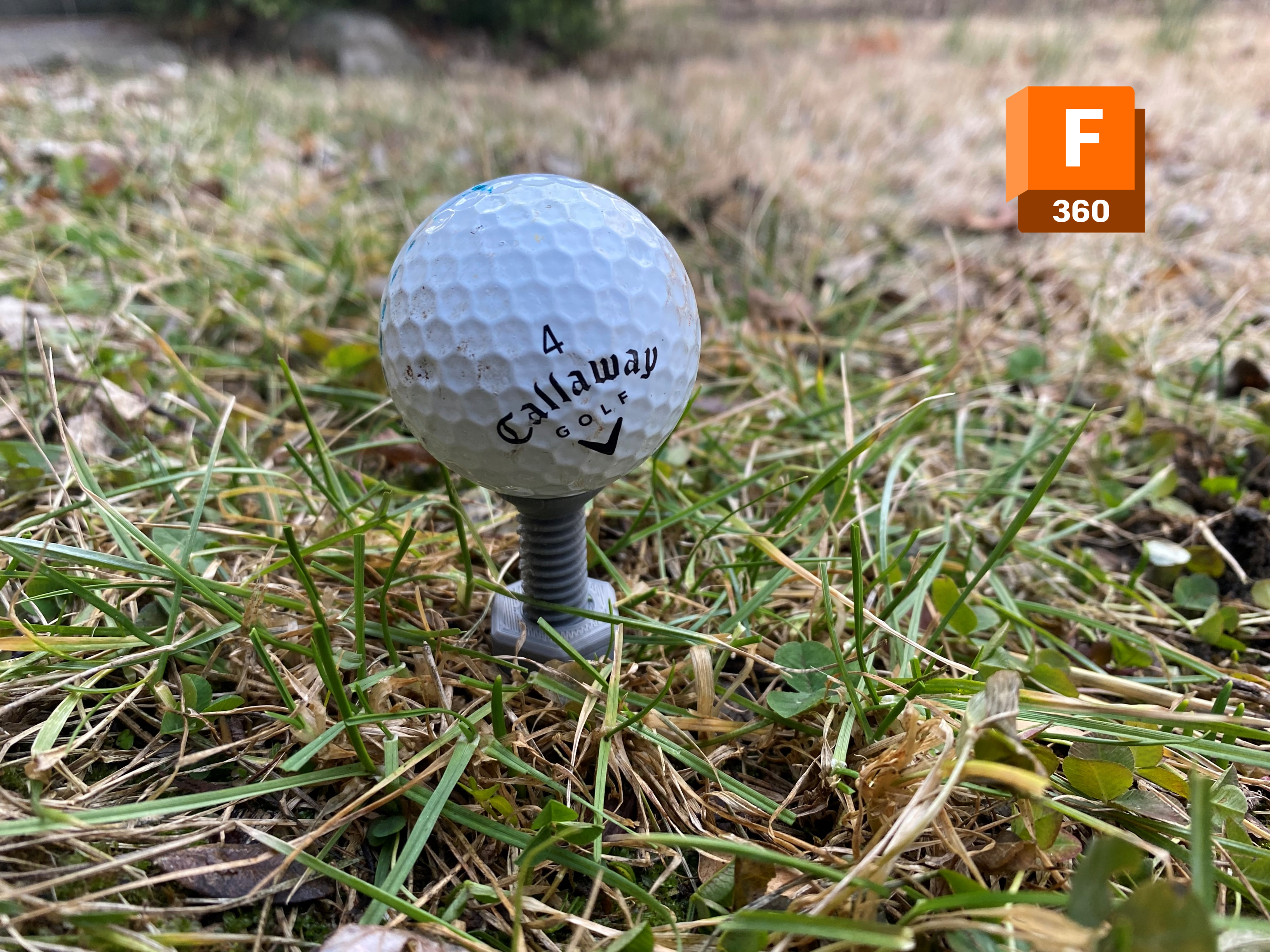
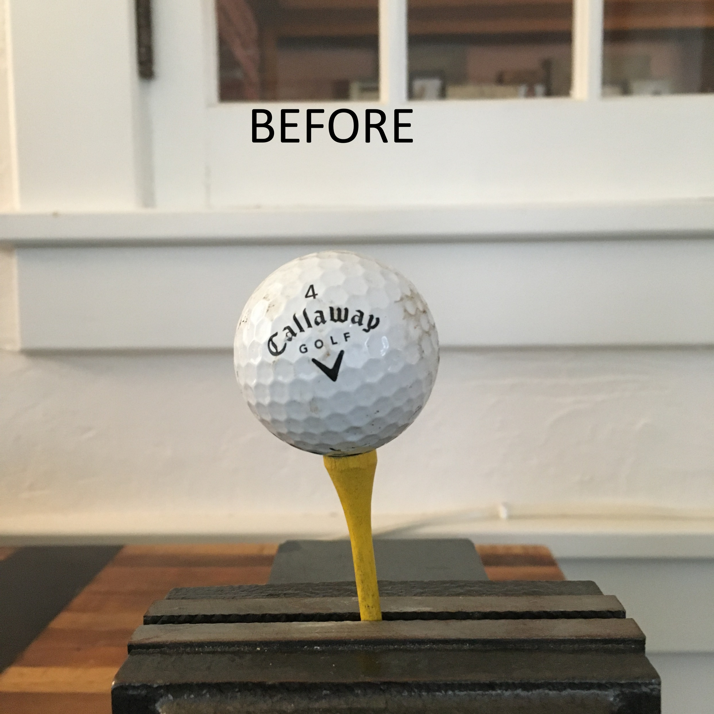
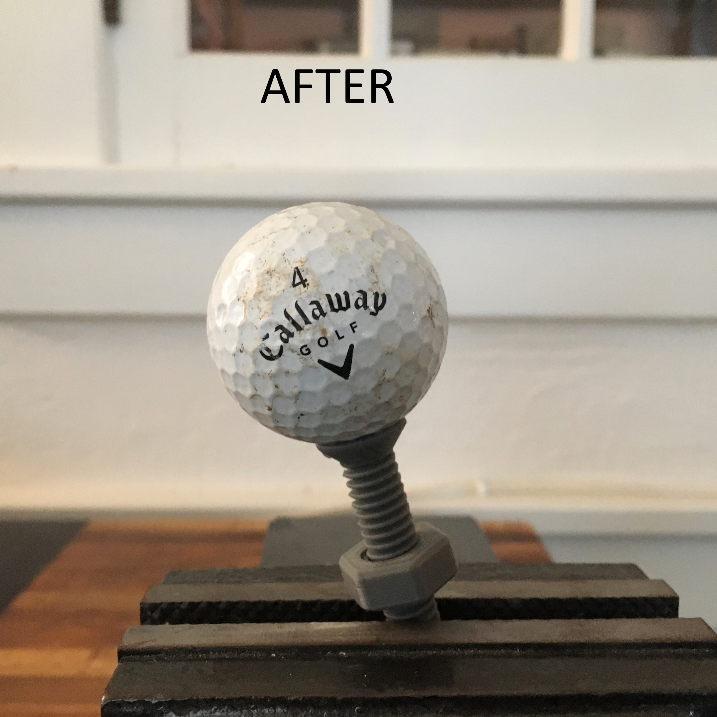
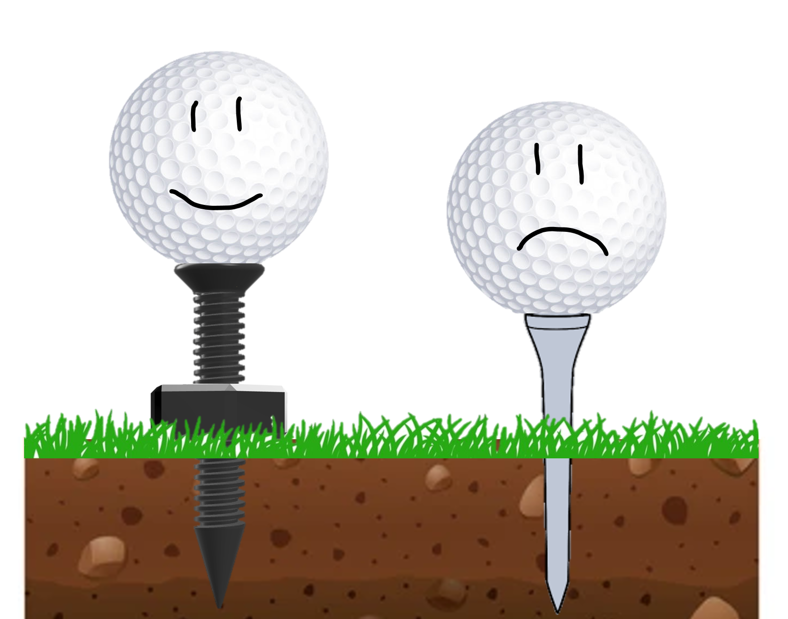
When I would play golf my tee would always go flying so I designed a tee that stays in the ground very good with threads. It can tilt at a 13-degree angle! vs a normal one can only tilt at an 8-degree angle 😲. It is adjustable with a nut so every time it is the same height.
Supplies
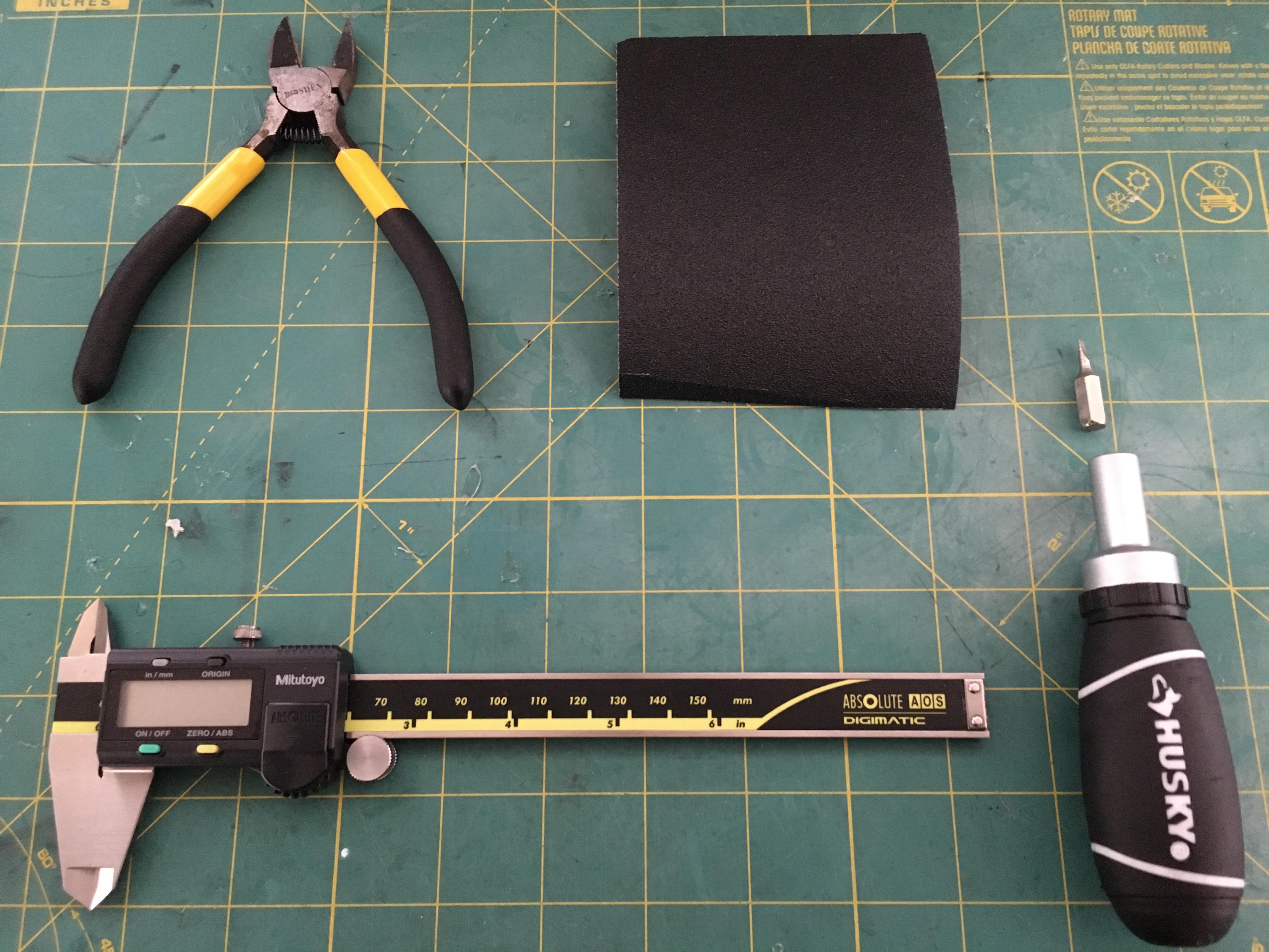
Cad
First download Autodesk fusion 360 then you are all set.
Sketch Body
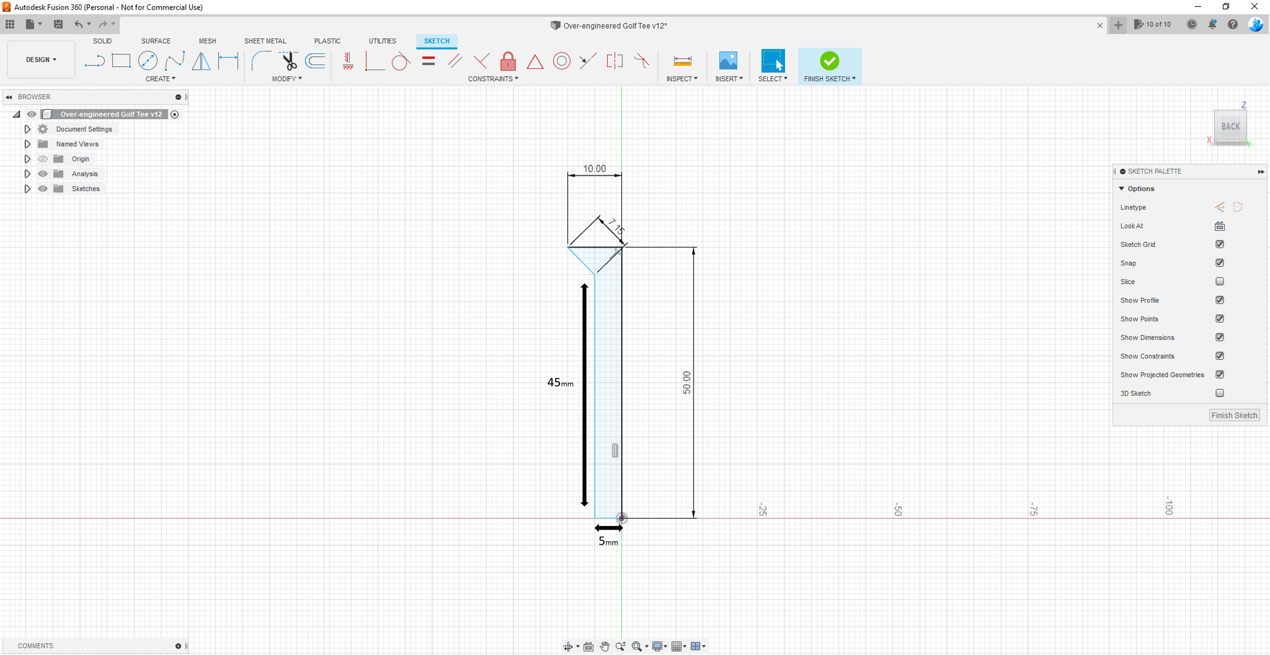
- Create a back view sketch.
- Create a line 50mm in height.
- At the bottom of the 50mm create a line on the x axis that is 5mm to the left.
- Create a line 44mm high at the end of the 5mm.
- Create a line on the 44mm diagonal left thru half of one of the grid cubes(look at the picture)
- Create a 10mm line connecting the golf tee.
- Finish the sketch
Revolve Body
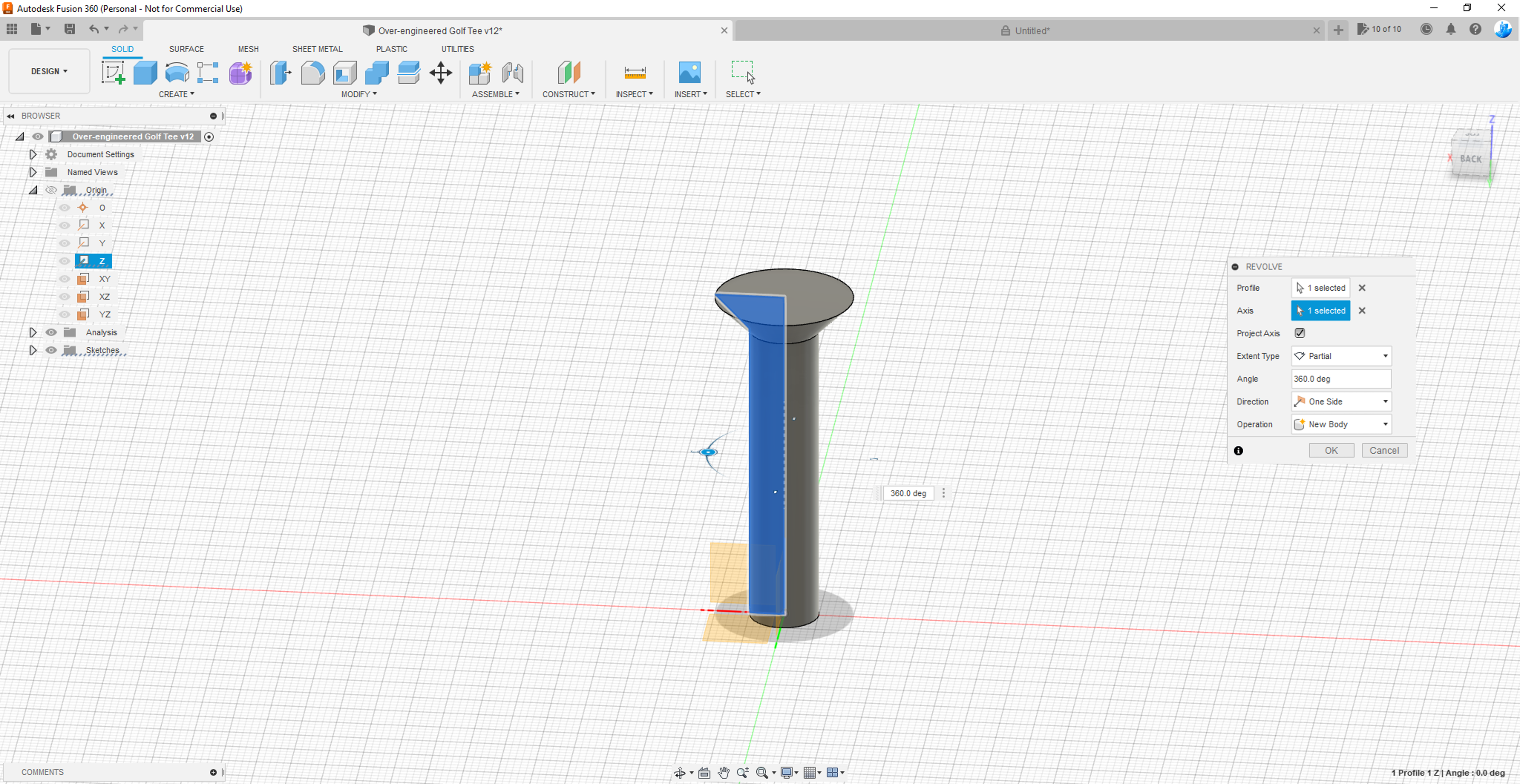
- Click create in the top left corner then revolve.
- Select the sketch.
- For the axis select the z axis.
- Angle 360.0 deg.
- Direction one side.
Sketch Ball Holder
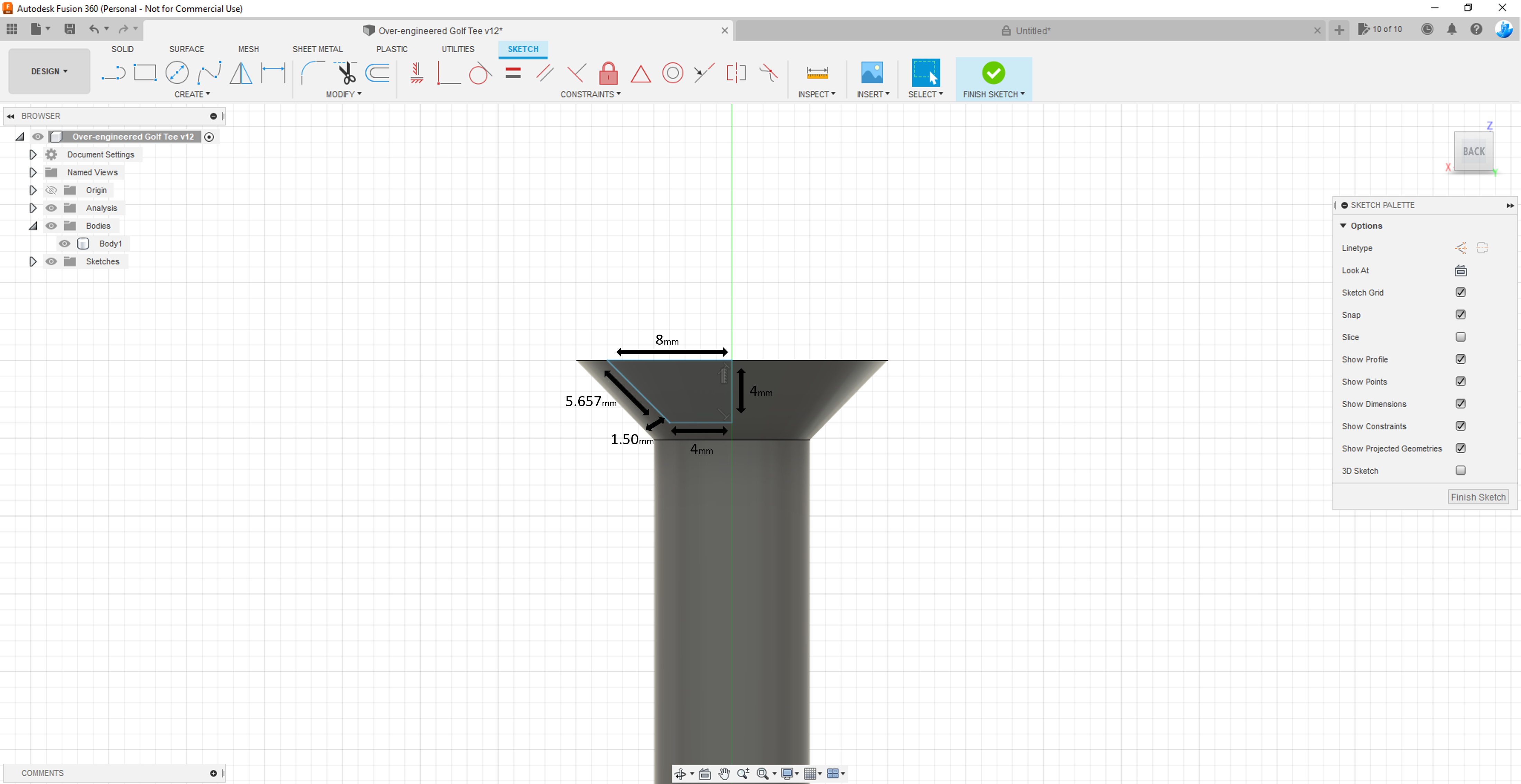
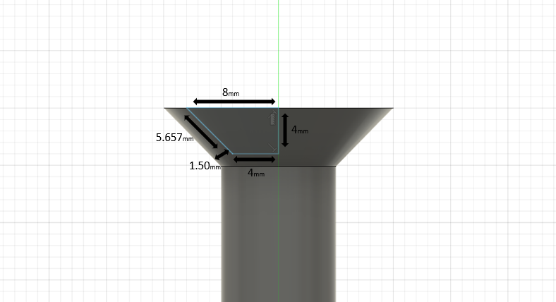
- Create a back view sketch.
- Start with a 4mm line across the y axis.
- At the bottom of that line do another 4mm line on the x axis. look at the picture.
- Create a left diagonal line spaced evenly up that is 5.657mm.
- Then 8mm line connecting them.
- Finish the sketch.
Revolve Ball Holder
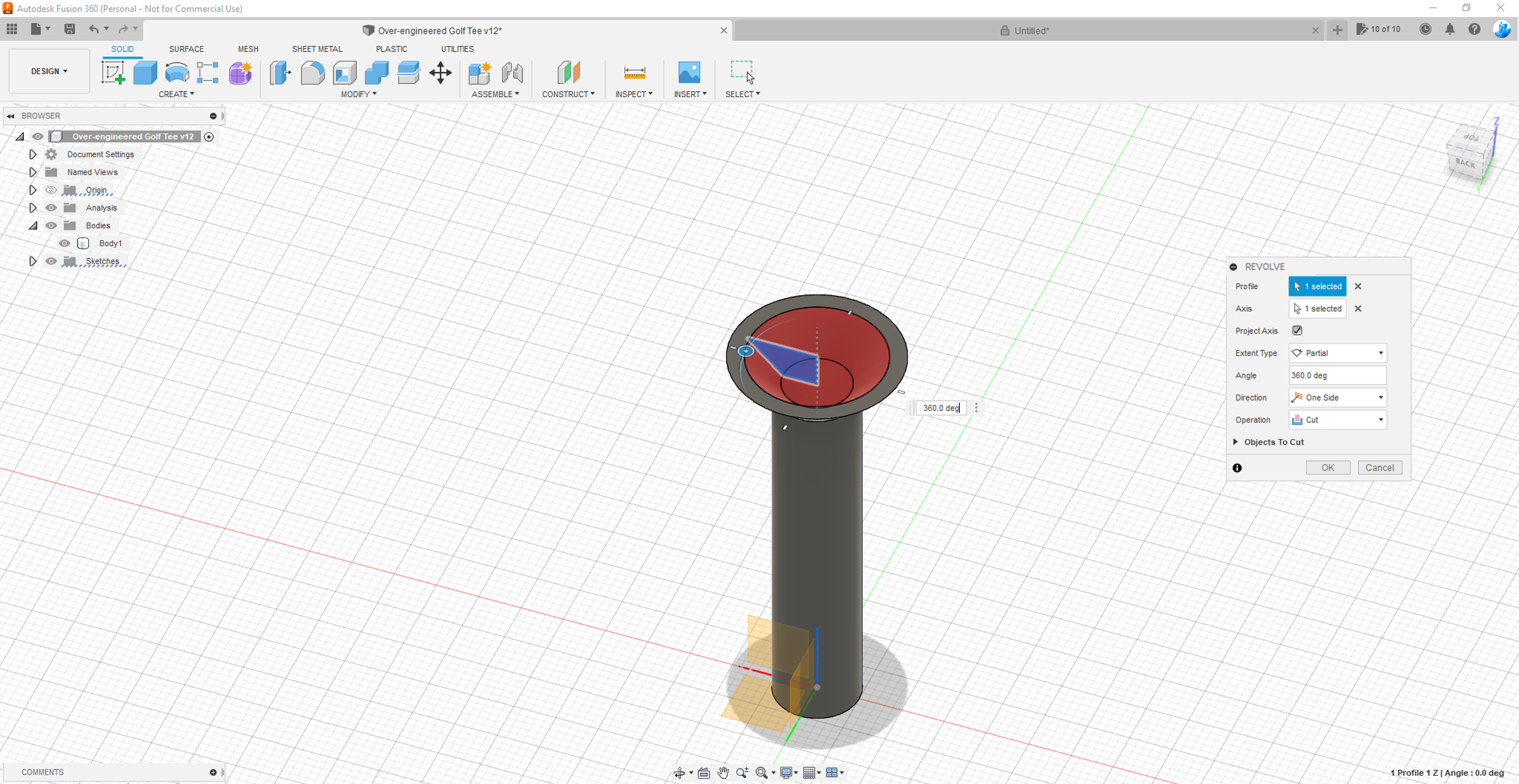
- Click revolve in create.
- Select the sketch.
- Z axis
- 360.0 deg
- Operation cut
Sketch Tip
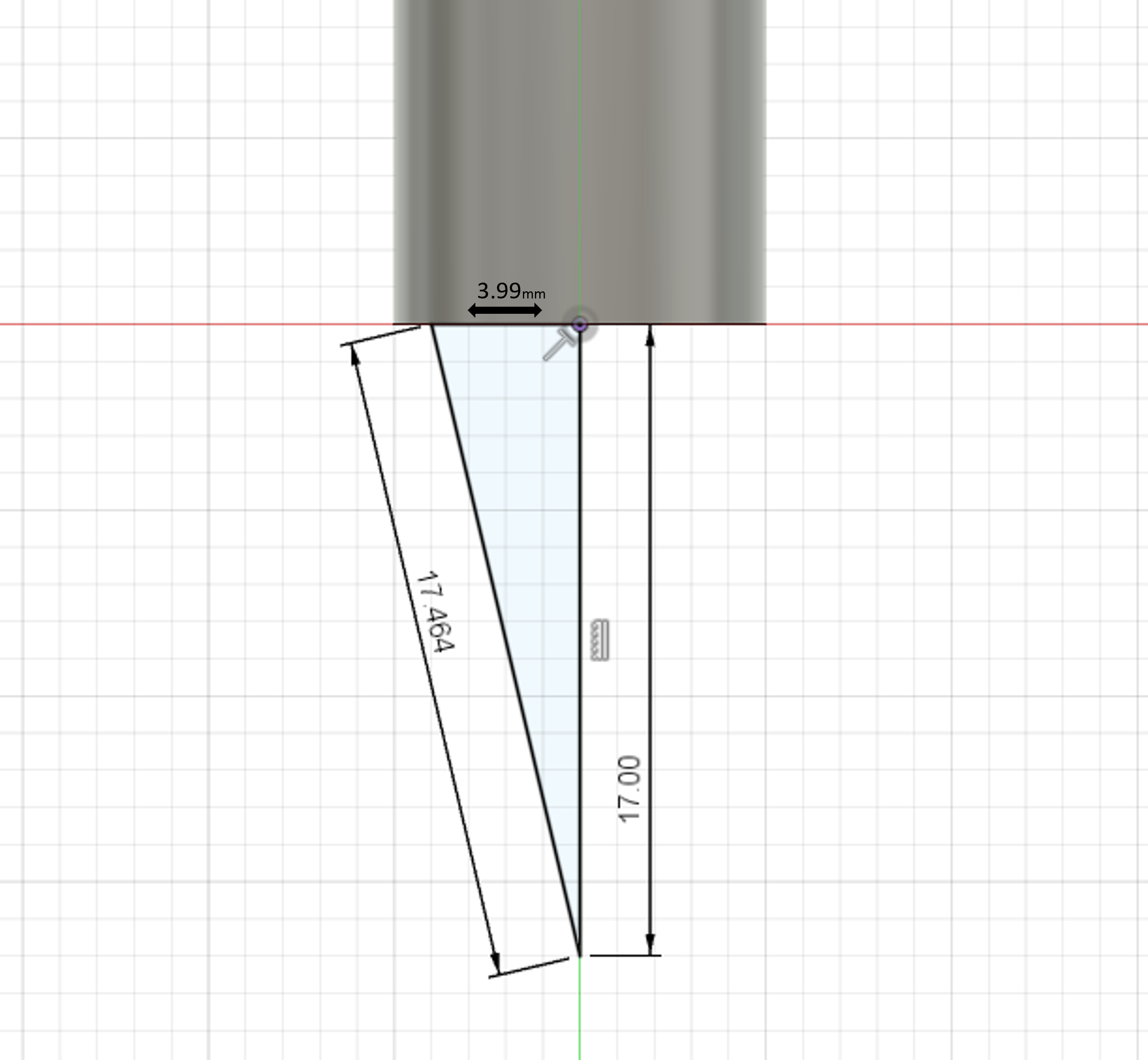
- Sketch a 17mm line on the y axis under the plane.
- Then a 17.464mm line back up diagonal to the left.
- Connect them with a line at 3.99mm.
- Finish sketch.
Revolve Tip
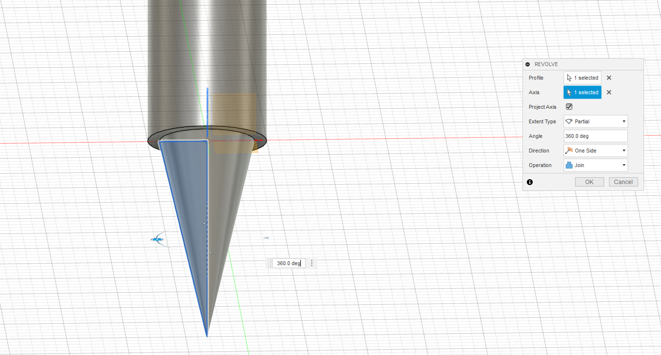
- Select revolve in create.
- Select the sketch.
- Z axis.
- 360.0 deg.
- Operation join.
Thread Body
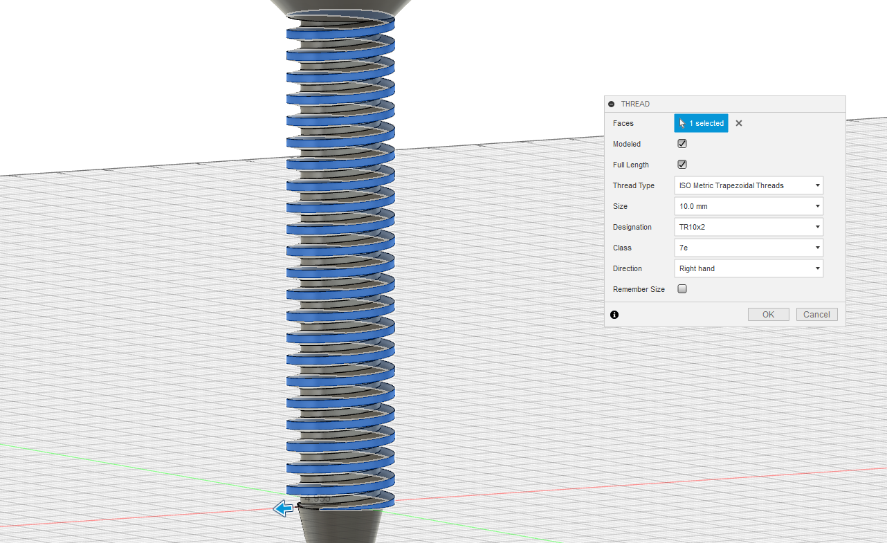
- Click create in the top left corner then thread.
- Select the the long cylinder.
- Select modeled and full length make sure you have a check mark.
- Thread type ISO metric trapezoidal threads.
- Designation TR10x2.
- Direction right hand.
Sketch Nut
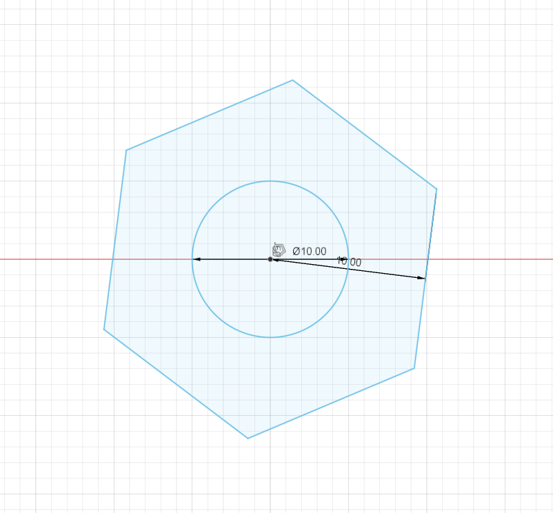
- Create a center diameter circle 10mm next to the tee.
- Click create then polygon circumscribed polygon start in the center then enter 10mm.
- Finish sketch.
Extrude Nut
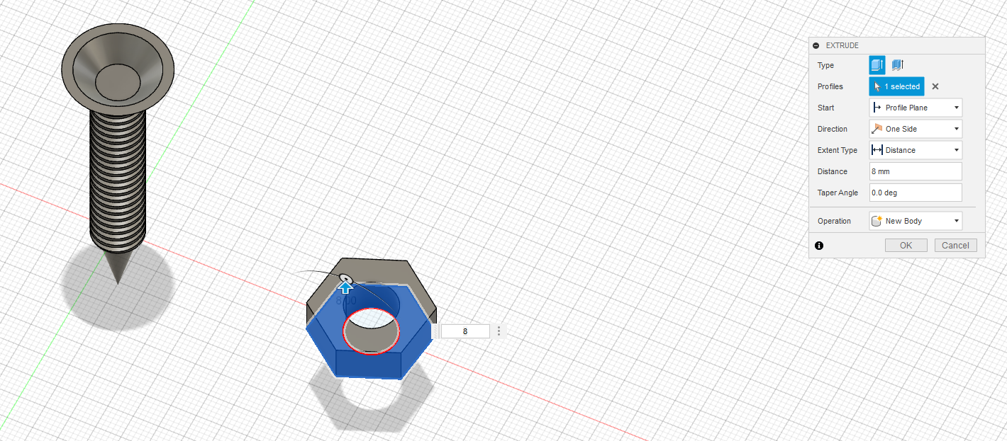
- Hit the e key for extrude select the sketch of the nut.
- Extrude to 8mm.
Thread Nut
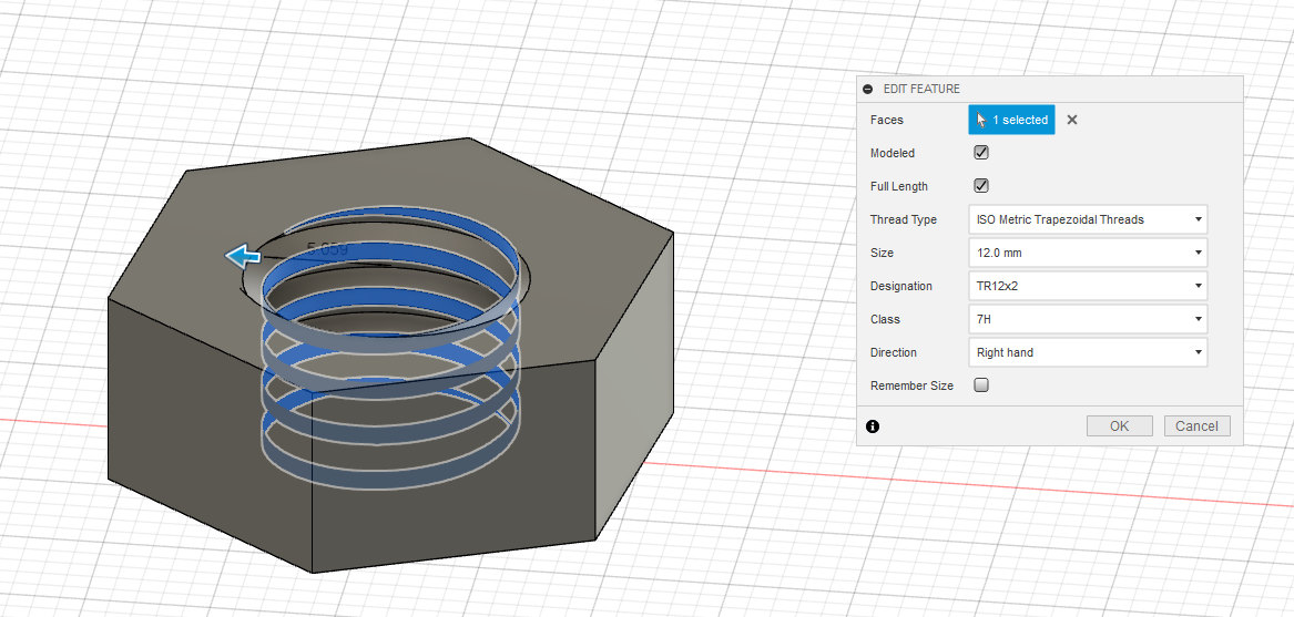
- Thread the nut with Thread type ISO metric trapezoidal threads with modeled and full length.
- Size 12mm
- Designation TR12x2.
- Direction right hand.
Fillet and Chamfer
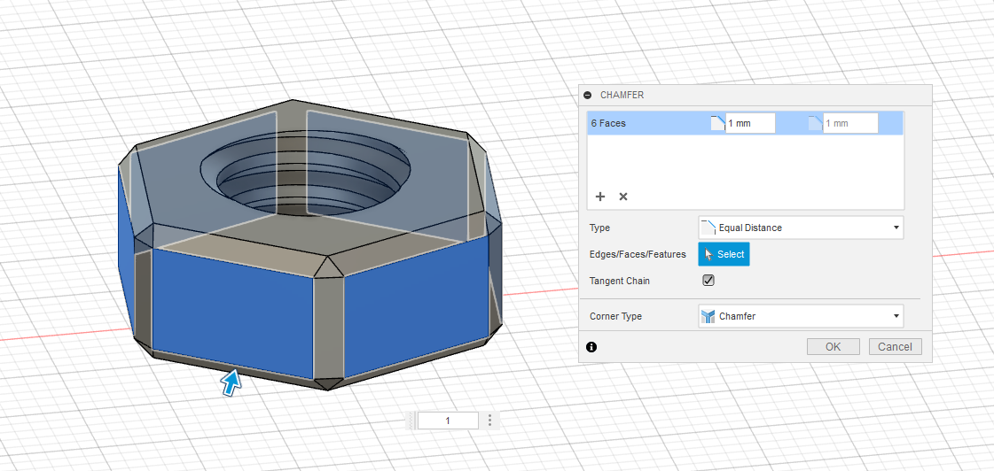
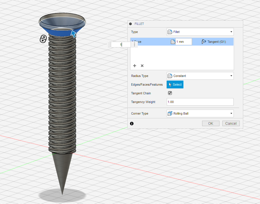
- Add a 1mm chamfer to the nut.
- Add a 1mm fillet to tee
Export
Go to file then export STL.
Slicing
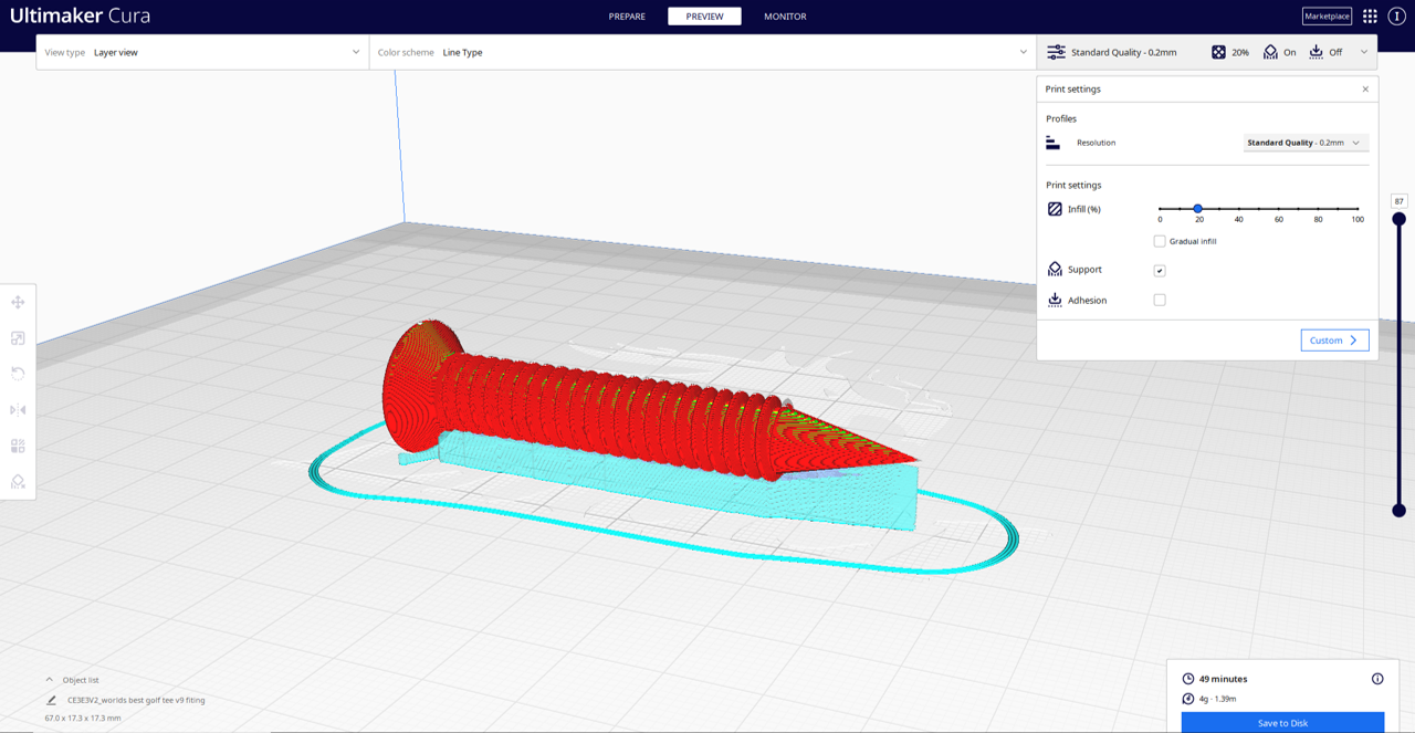
Print the tee with supports on its side 20% infill
Print the nut with no supports(yes this matters) 20% infill.
Printing
- Filament PLA or ABS.
- 20% infill.
- The nut is 15 minutes and the tee is 50 minutes.
Taking Supports Off
Start at the tip then with your snippers start taking the supports off.
Sanding
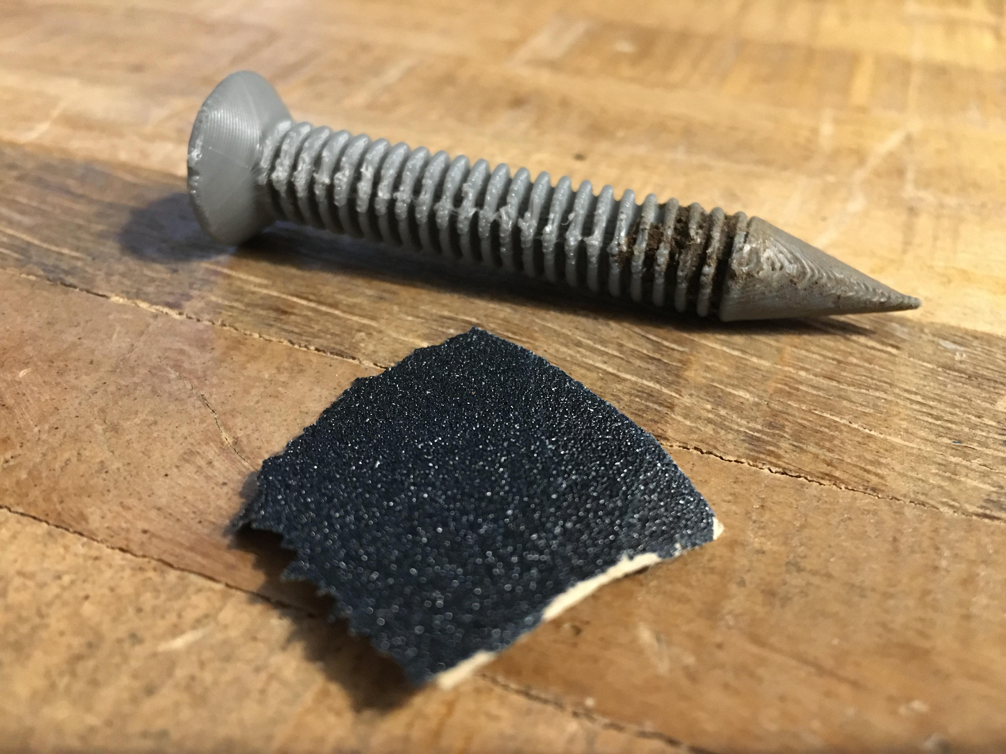
On the thread if you have some PLA between the each gap(don't panic) just sand it down till it is all gone.
Getting More PLA Out
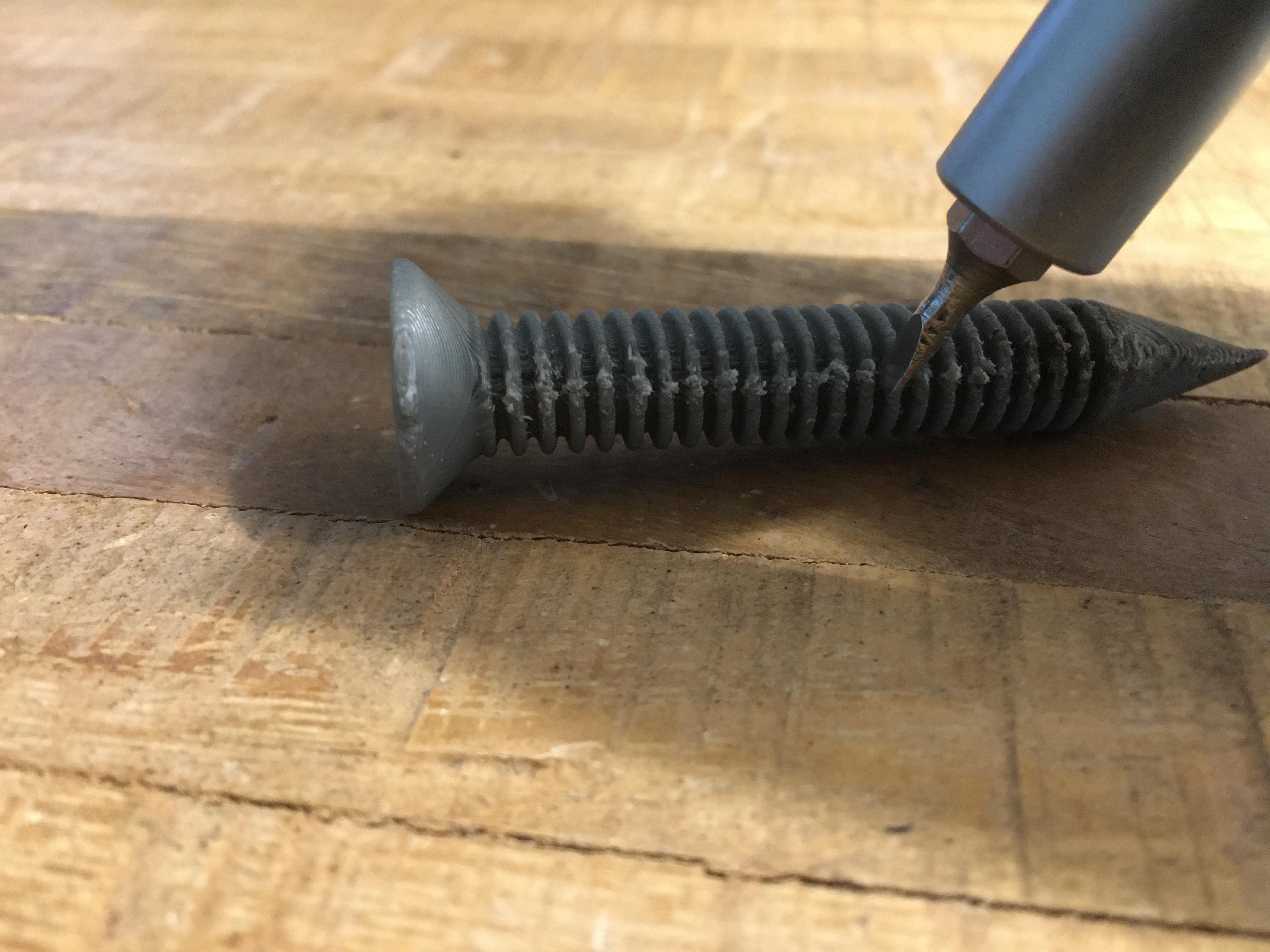
Use a screwdriver to get the rest of the PLA out.
Nut Not Fitting On
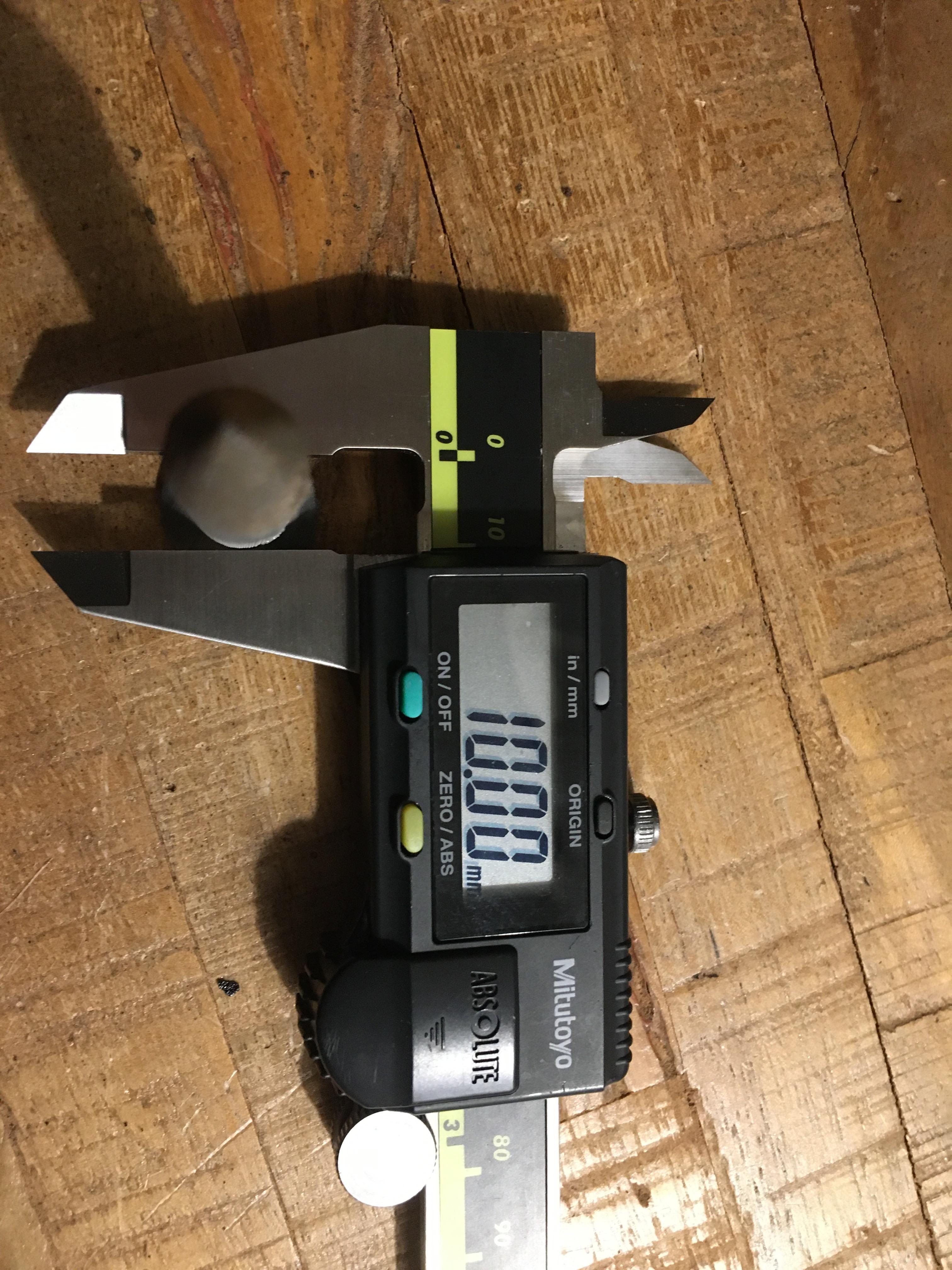
Make sure your body is 10mm.
U R Done
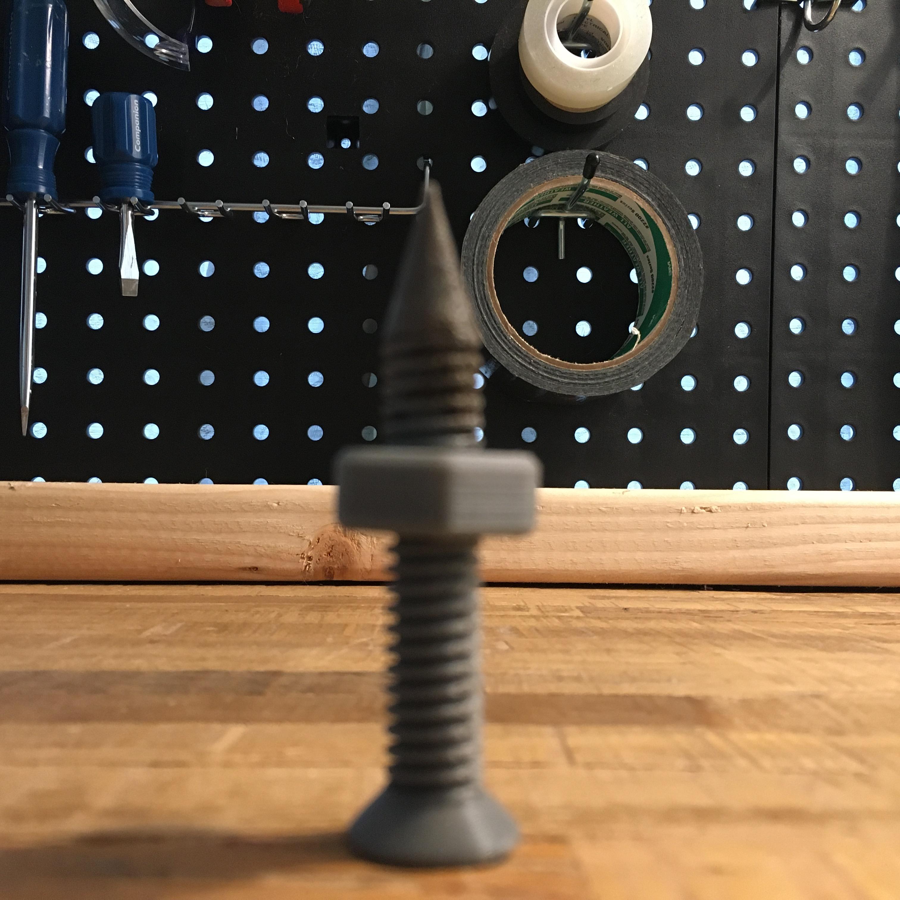
Hope this was helpful.