Otto Robot for EMTX

Welcome to my guide on how to assemble your very own Otto the Robot.
Follow these steps and refer to your own personal guide to create this funky little fella.
Supplies
Screwdriver
File (if needed)
Scissors to cut plastic
Also include mask if additional filing is necessary.
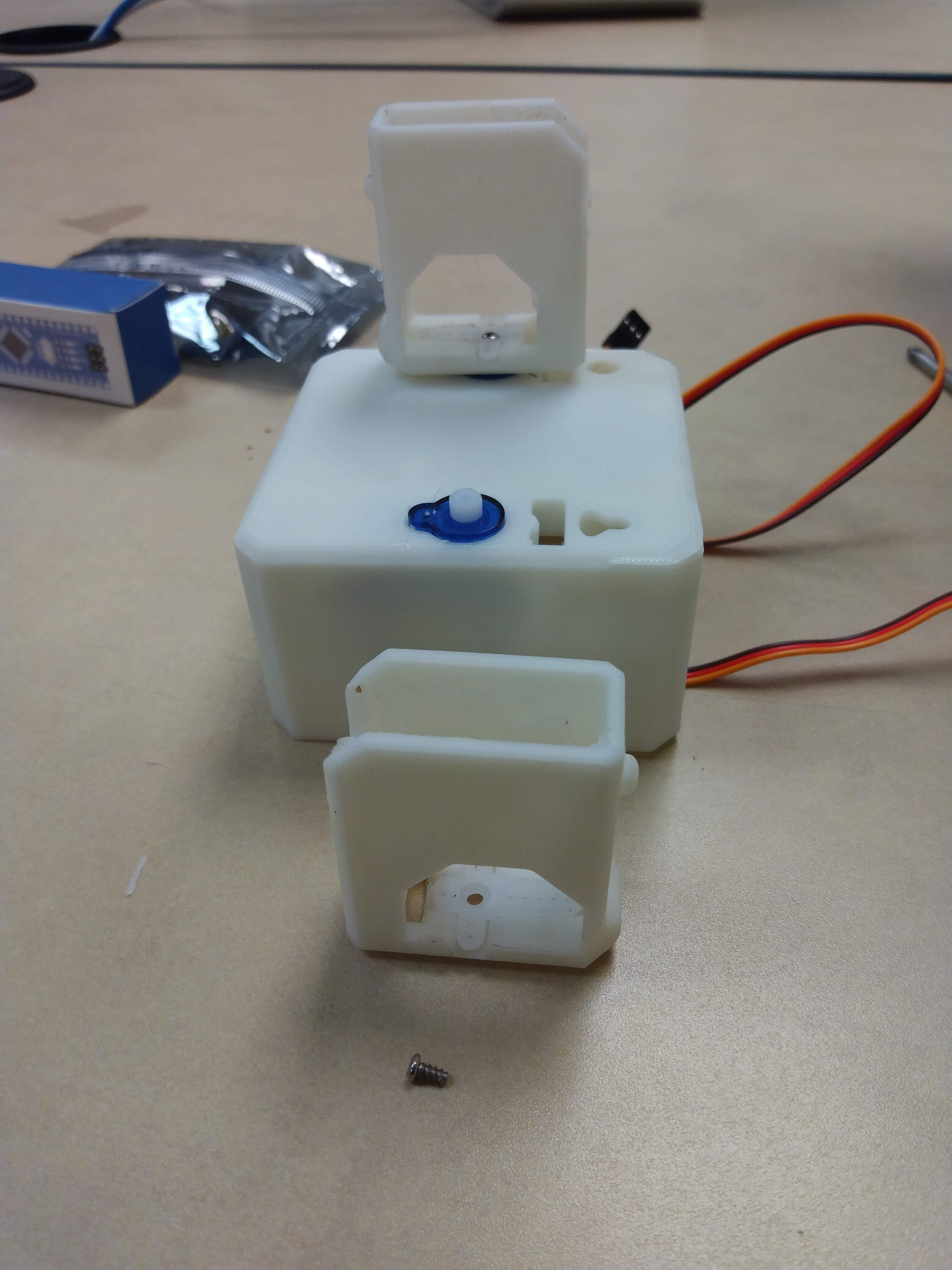
Cut and Trim Your Plastic Foot Holds
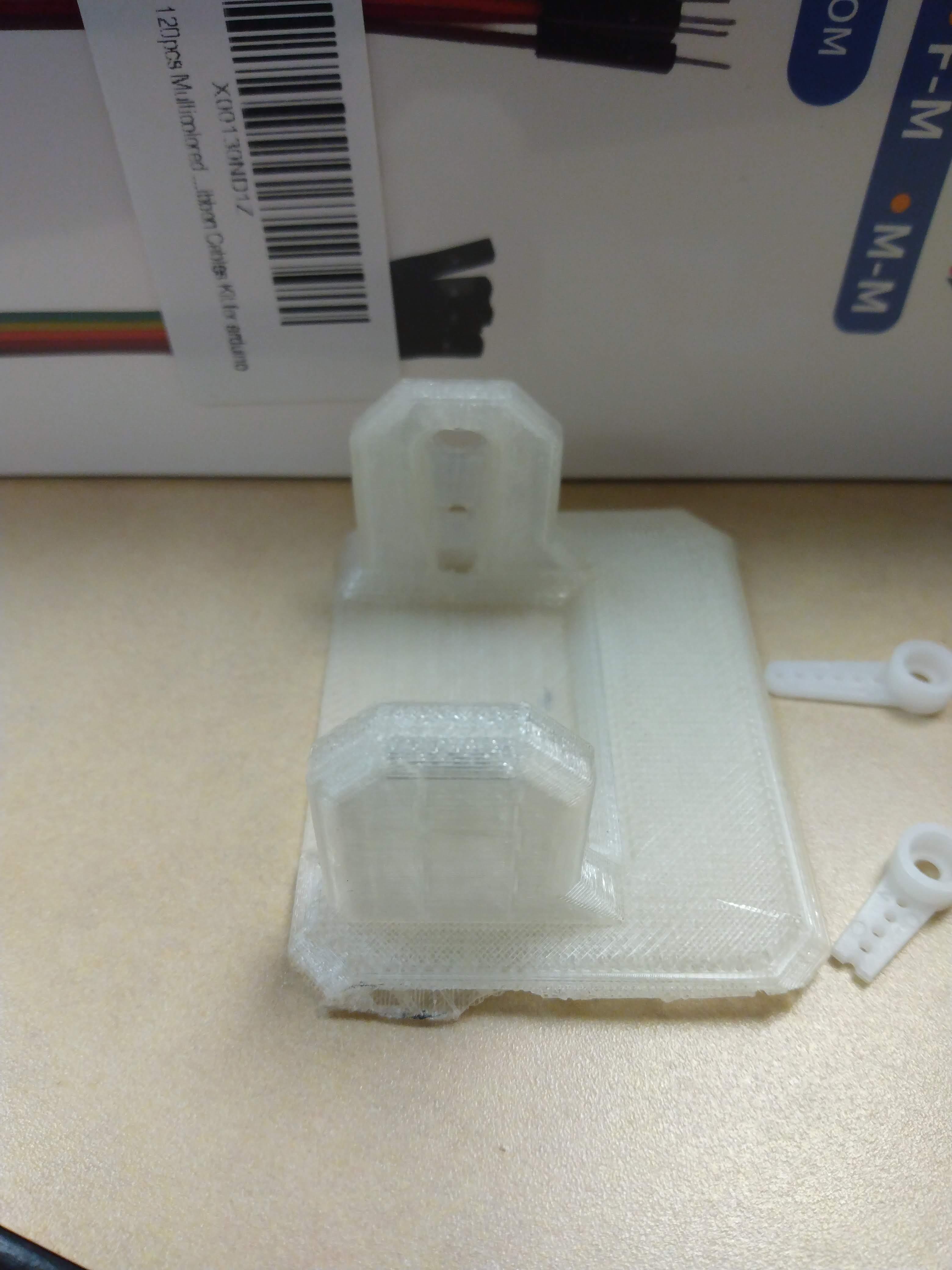
These have to be cut similar to the 5th slot, half way through.
So they can sit neatly within the grooves of the foot.
Once Done, Screw Servos Onto the Feet
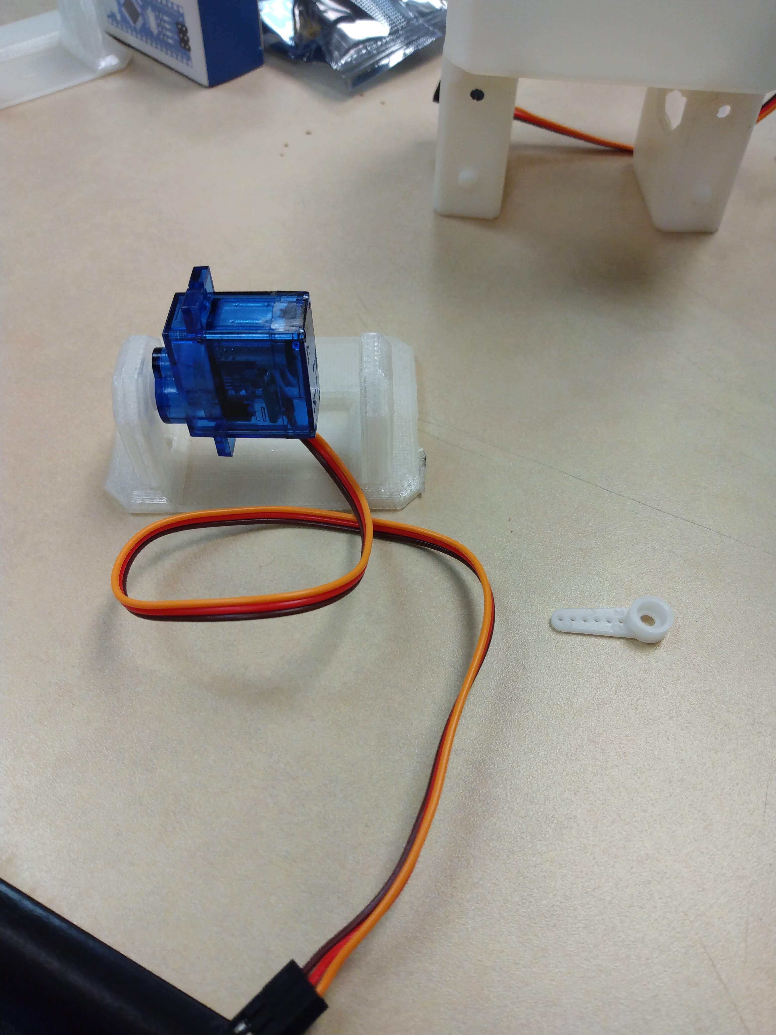
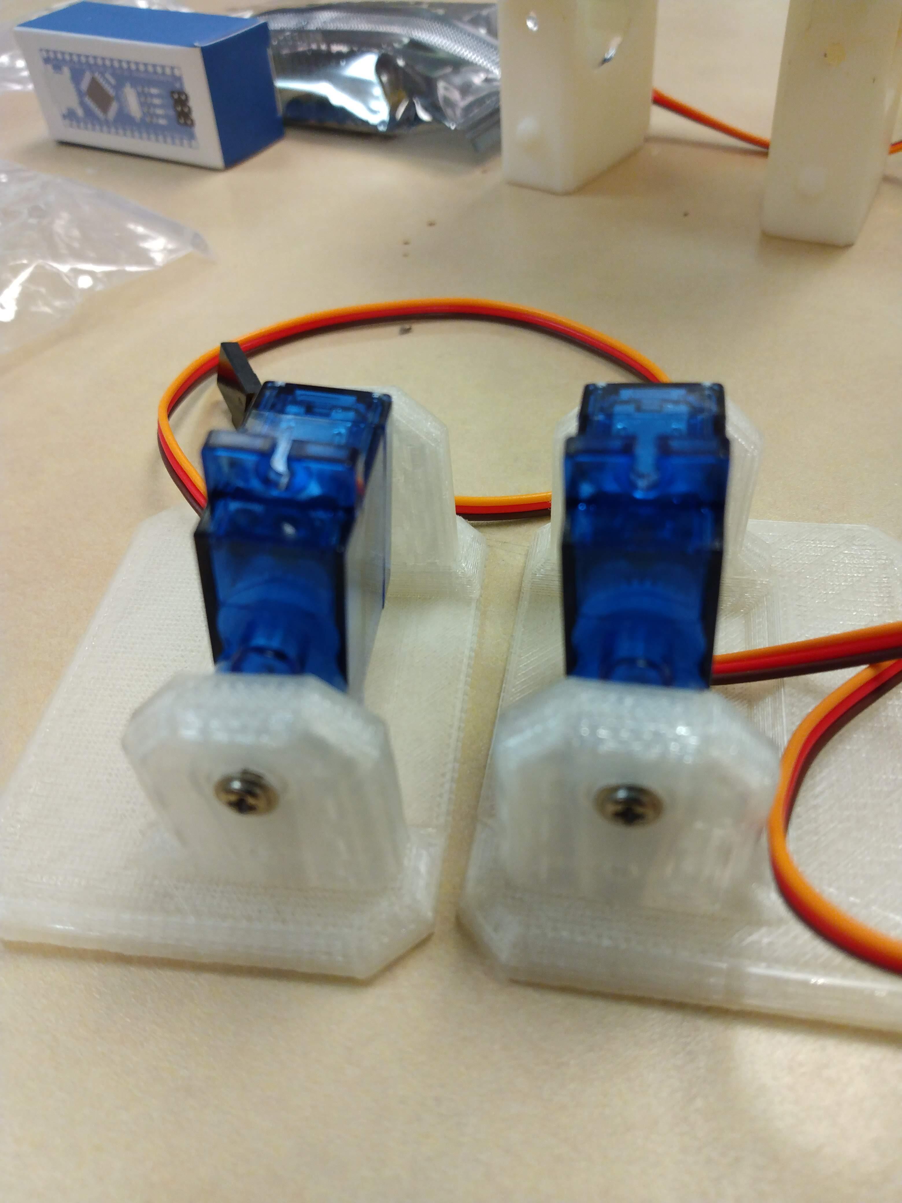
Once set, put the servos in the foot holds, and screw down tightly.
Not too tight to where the plastic breaks.
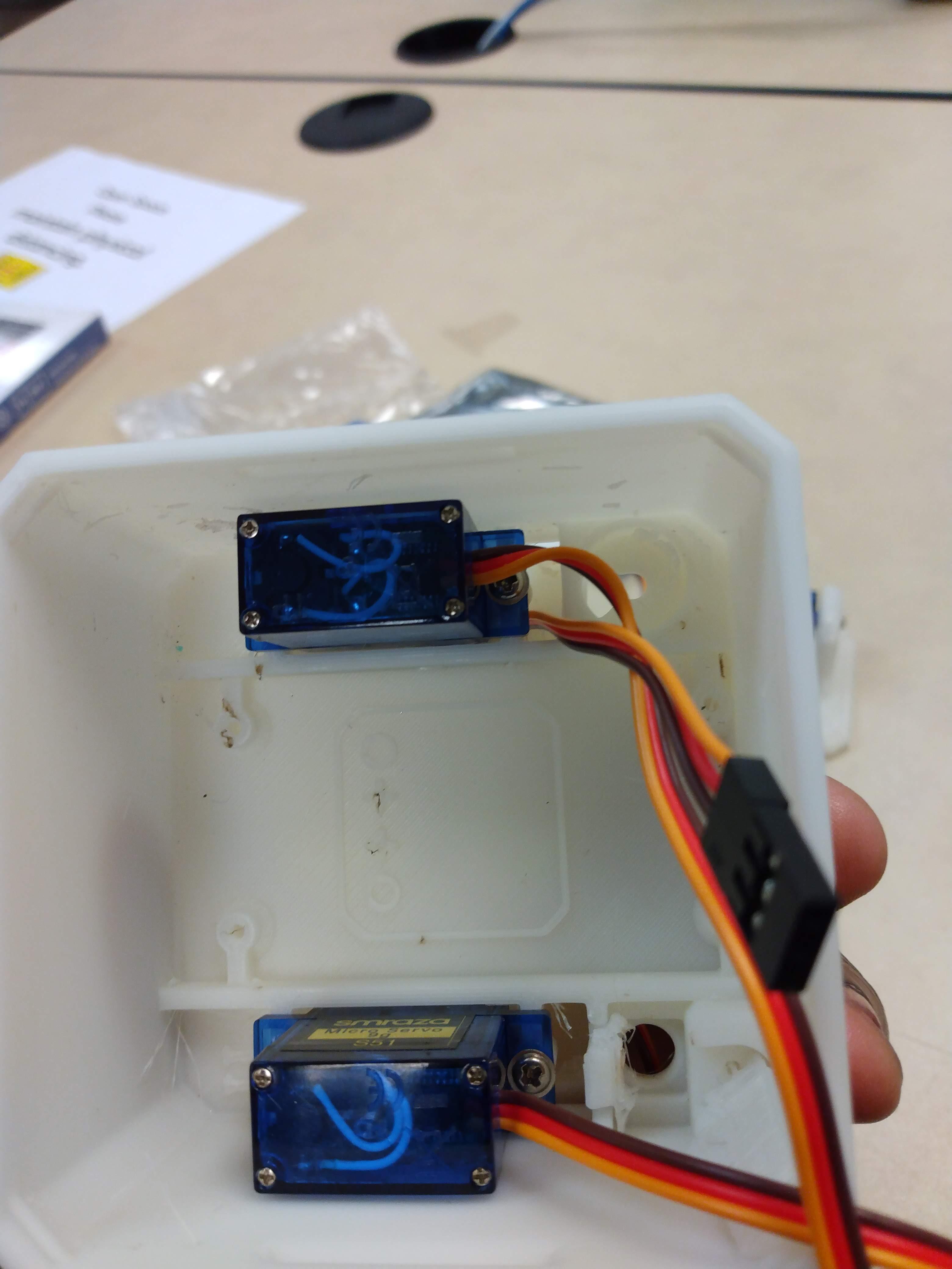
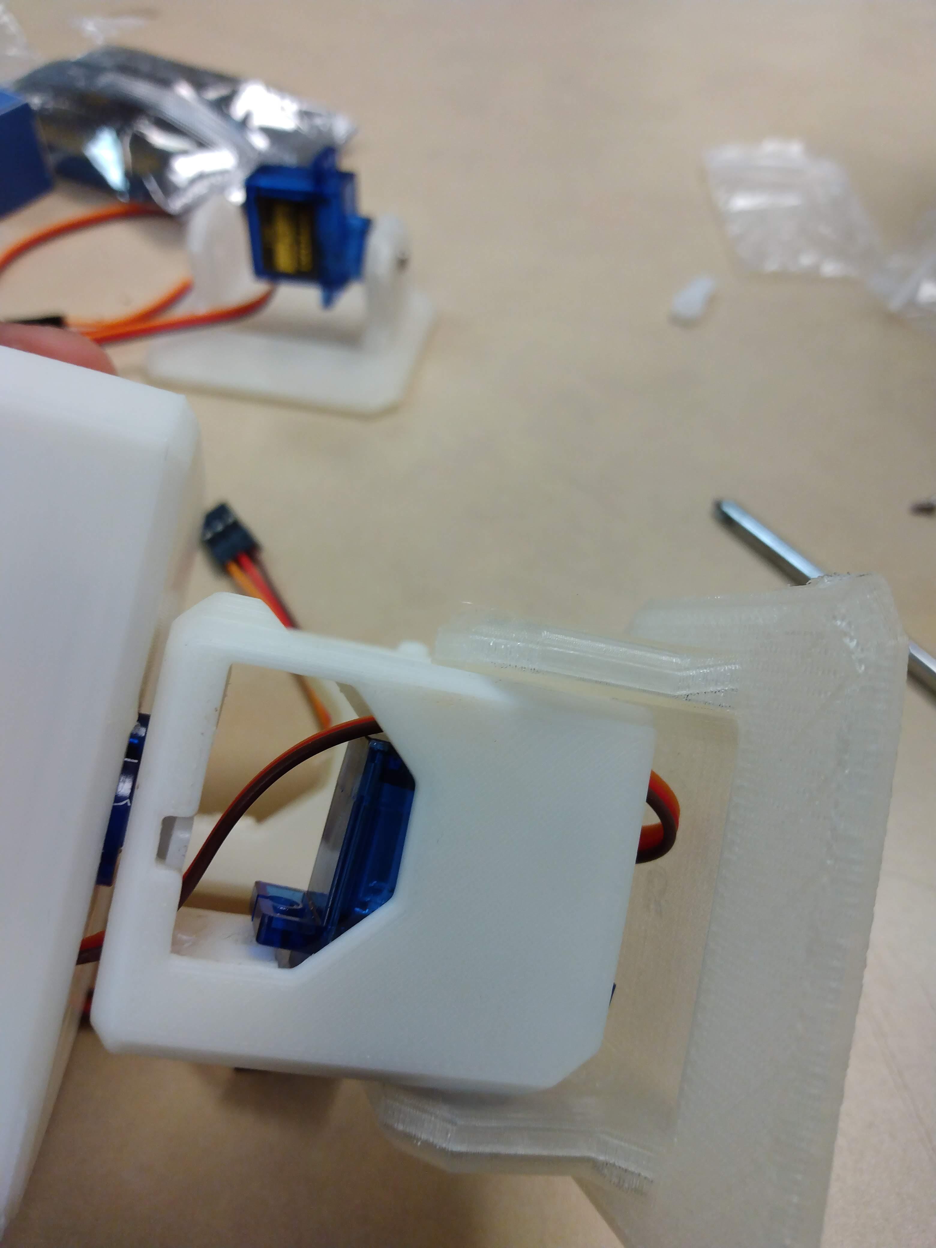
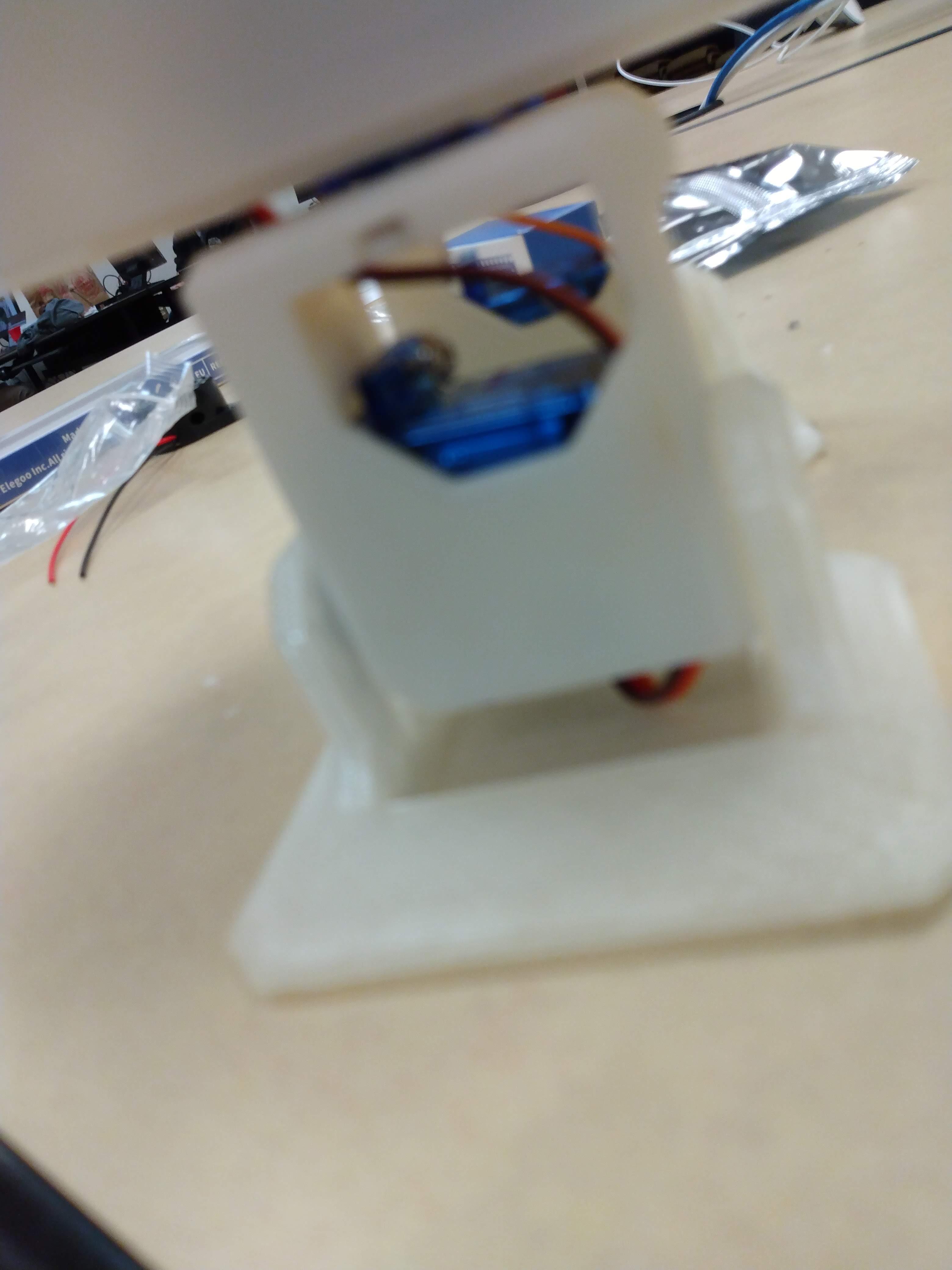
Placing the Servos in the Bottom Chassis
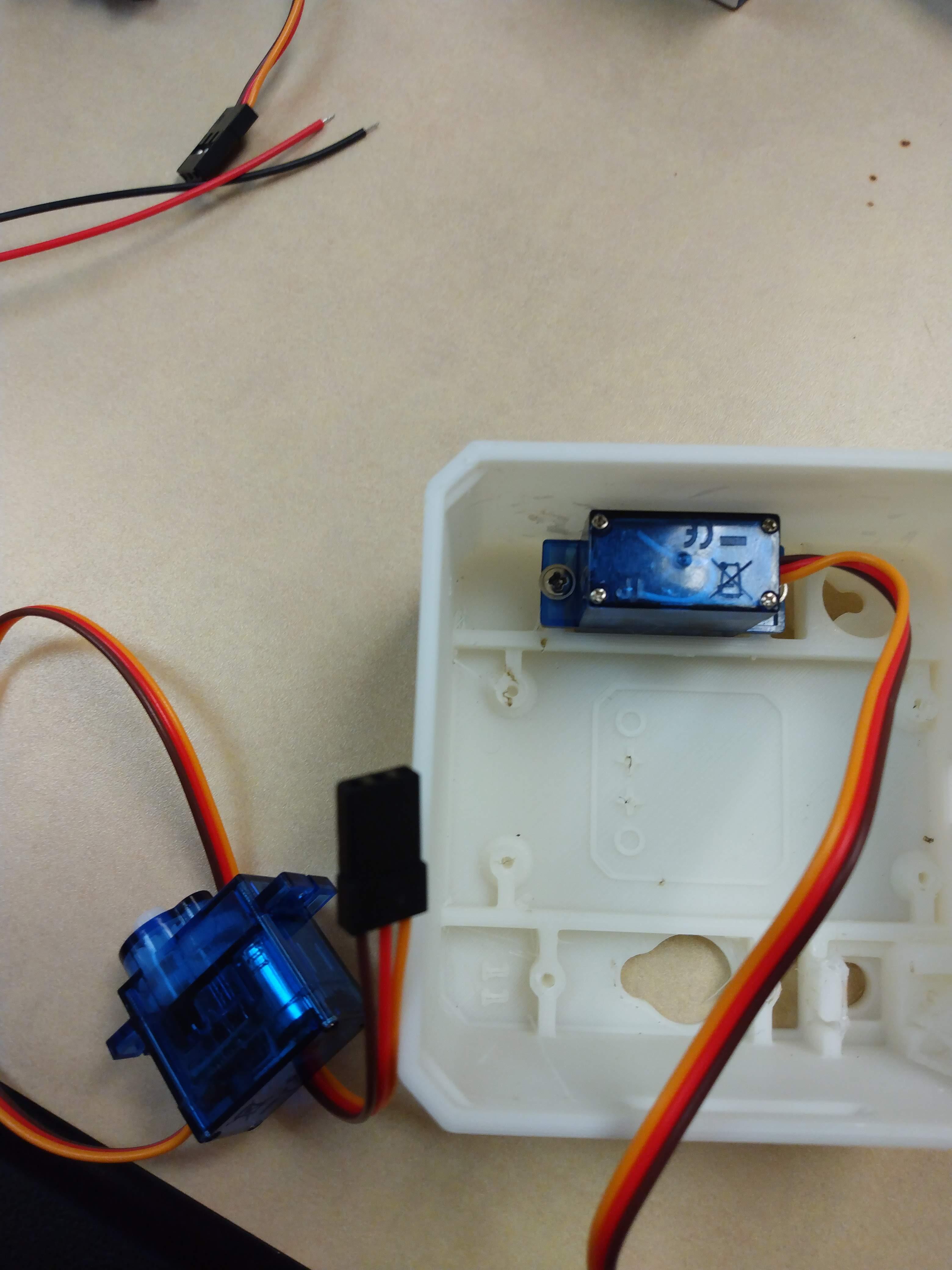
Place both servos in the bottom of Otto's chassis with the cords facing the next open hole on the right.
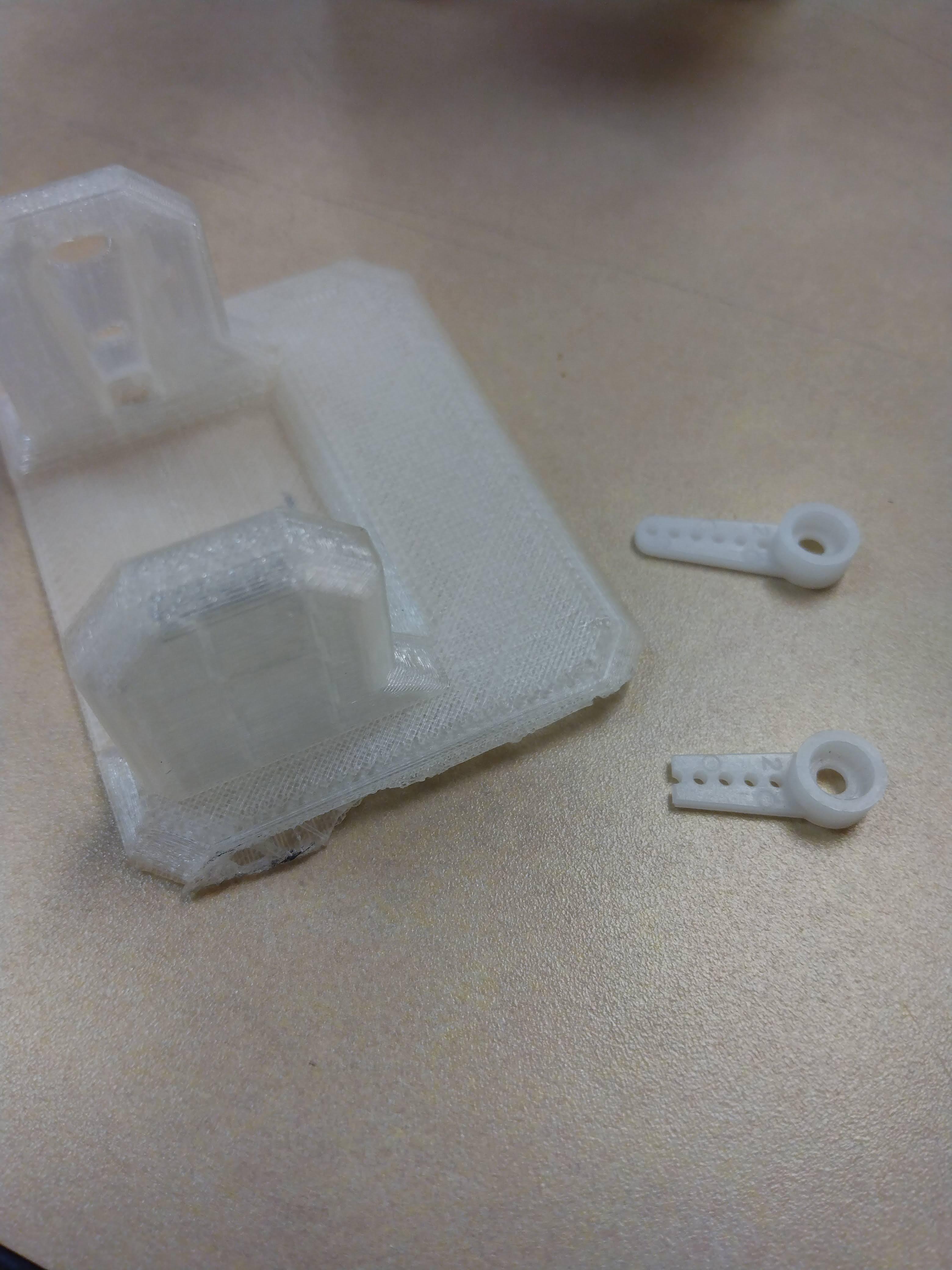
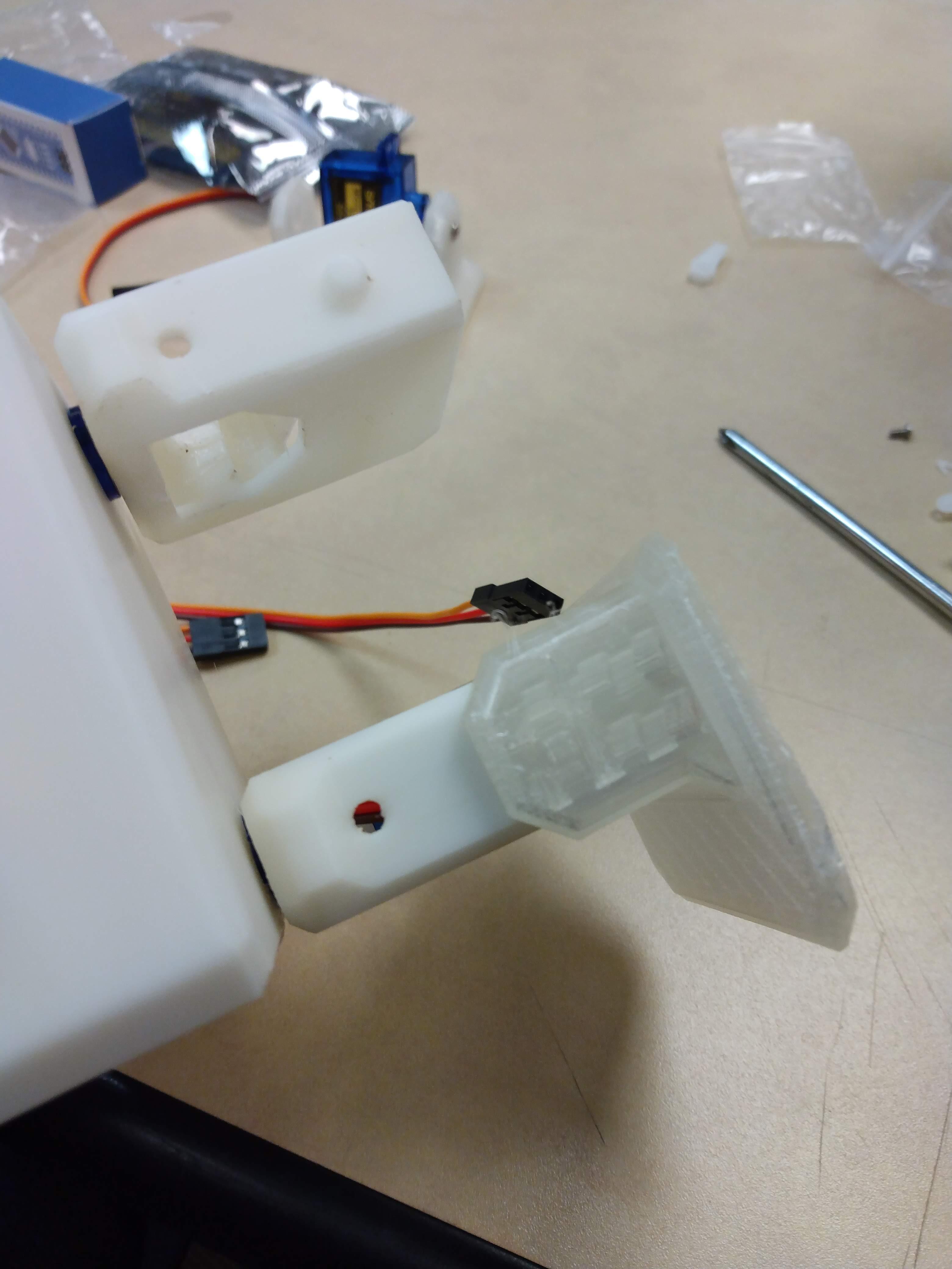
Cut and Trim the Plastic Holds for the Legs
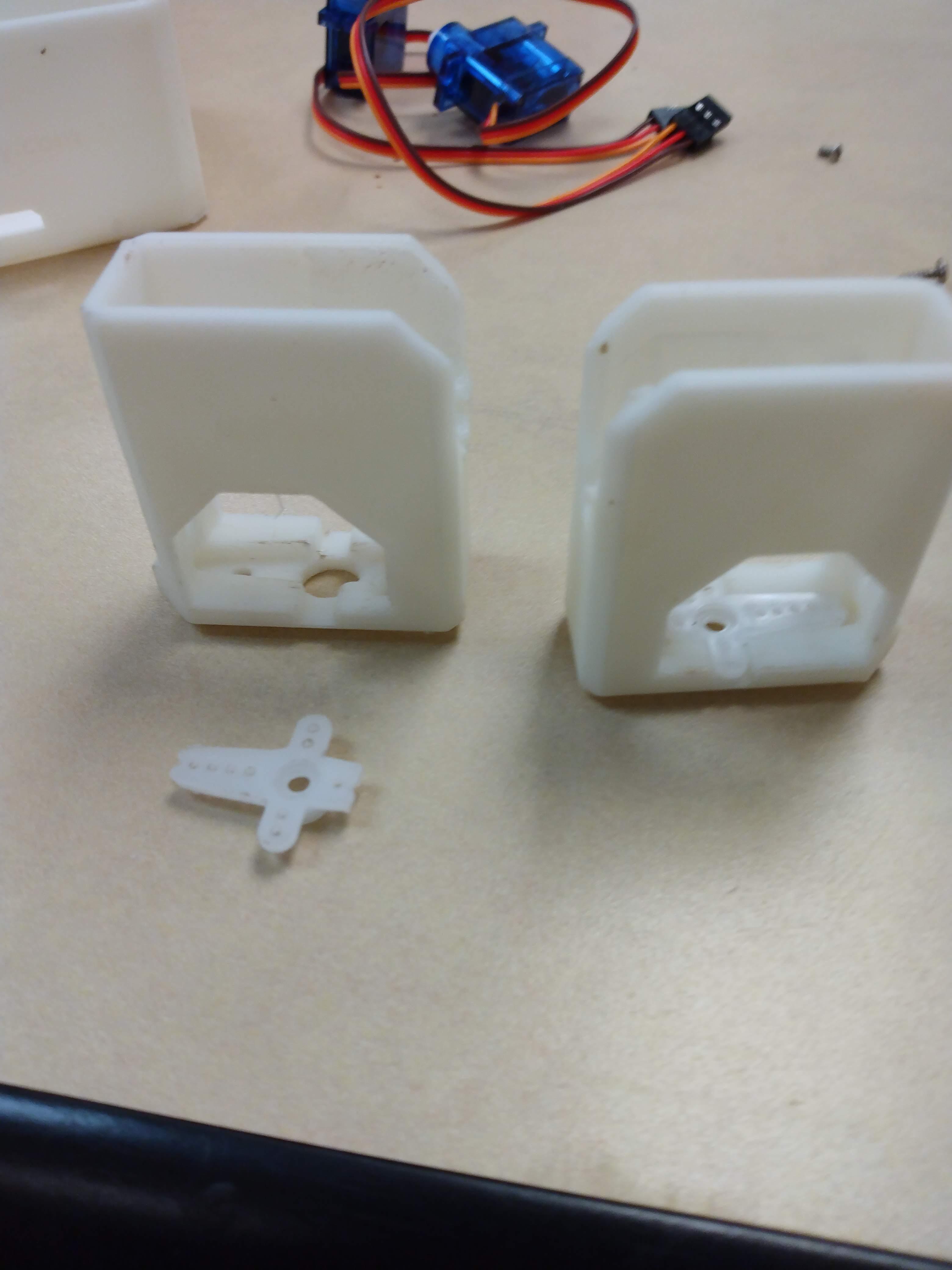
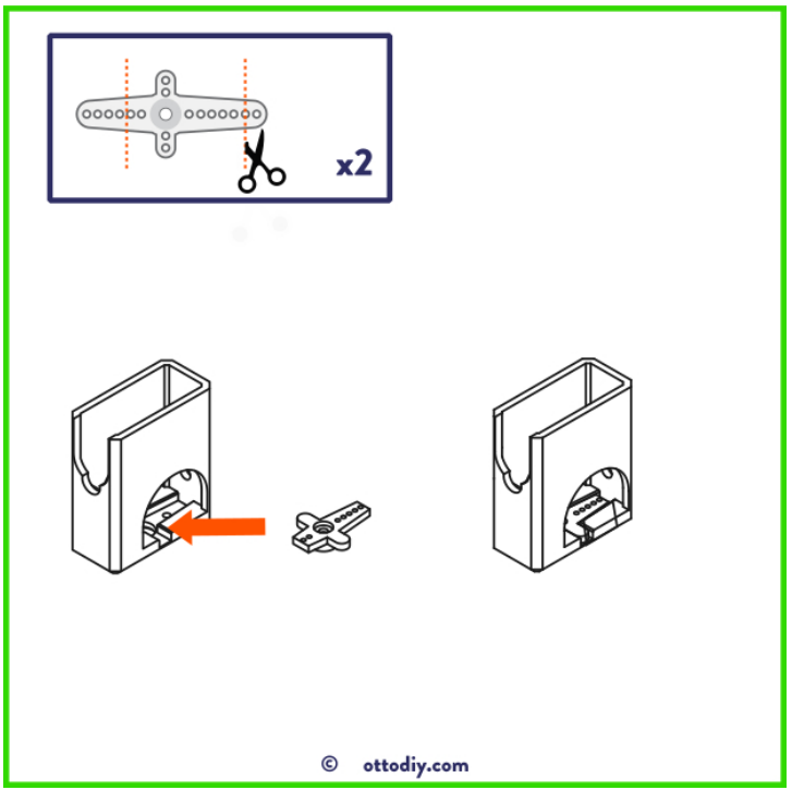
Cut the plastic star holds similar to the diagram and they should fit neatly within the provided groove for the legs.
Attach and Screw the Legs to the Servos
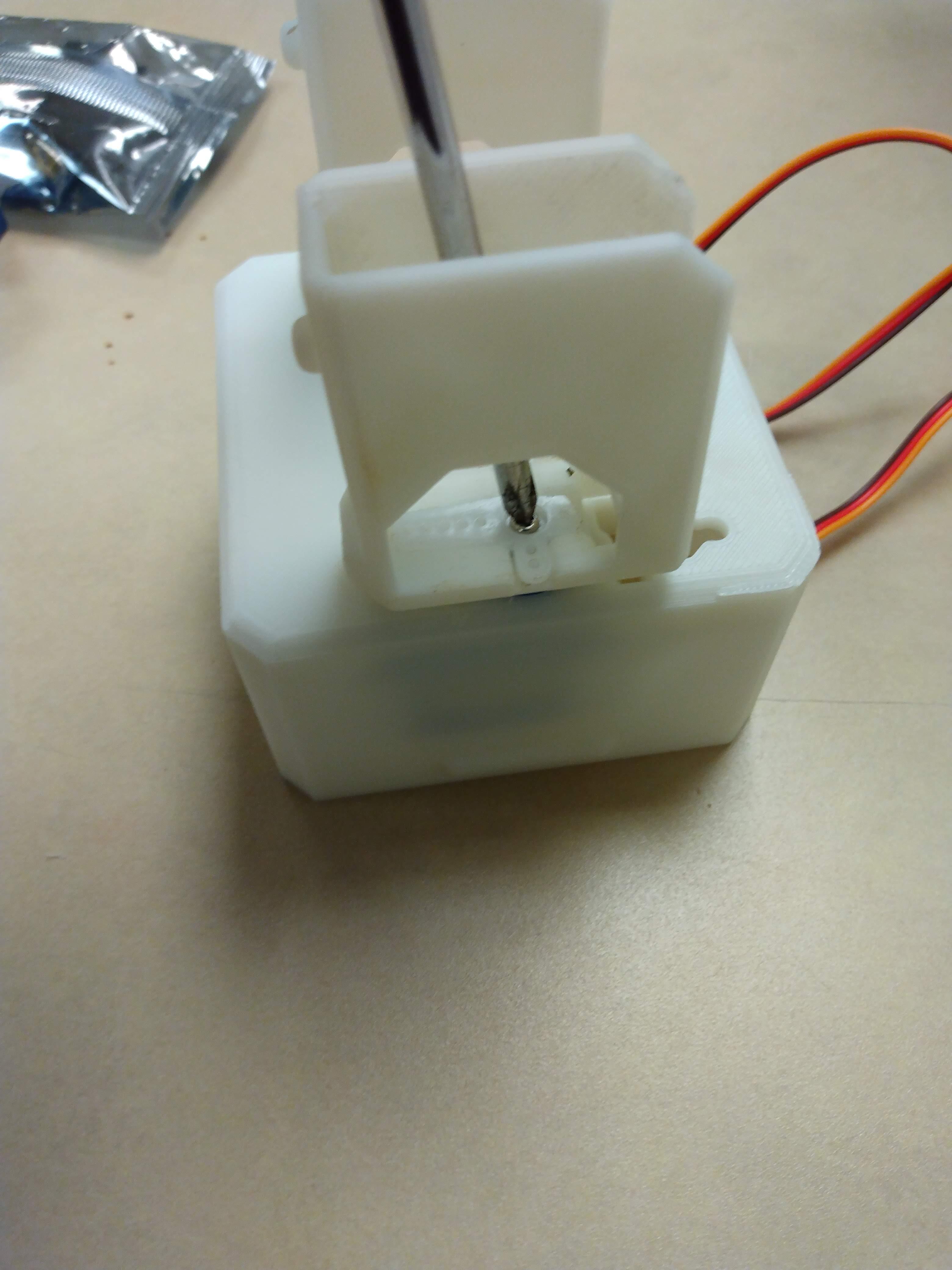
Make sure the plastic parts line up and can fit the leg.
You don't want the leg to move or wobble unnecessarily.
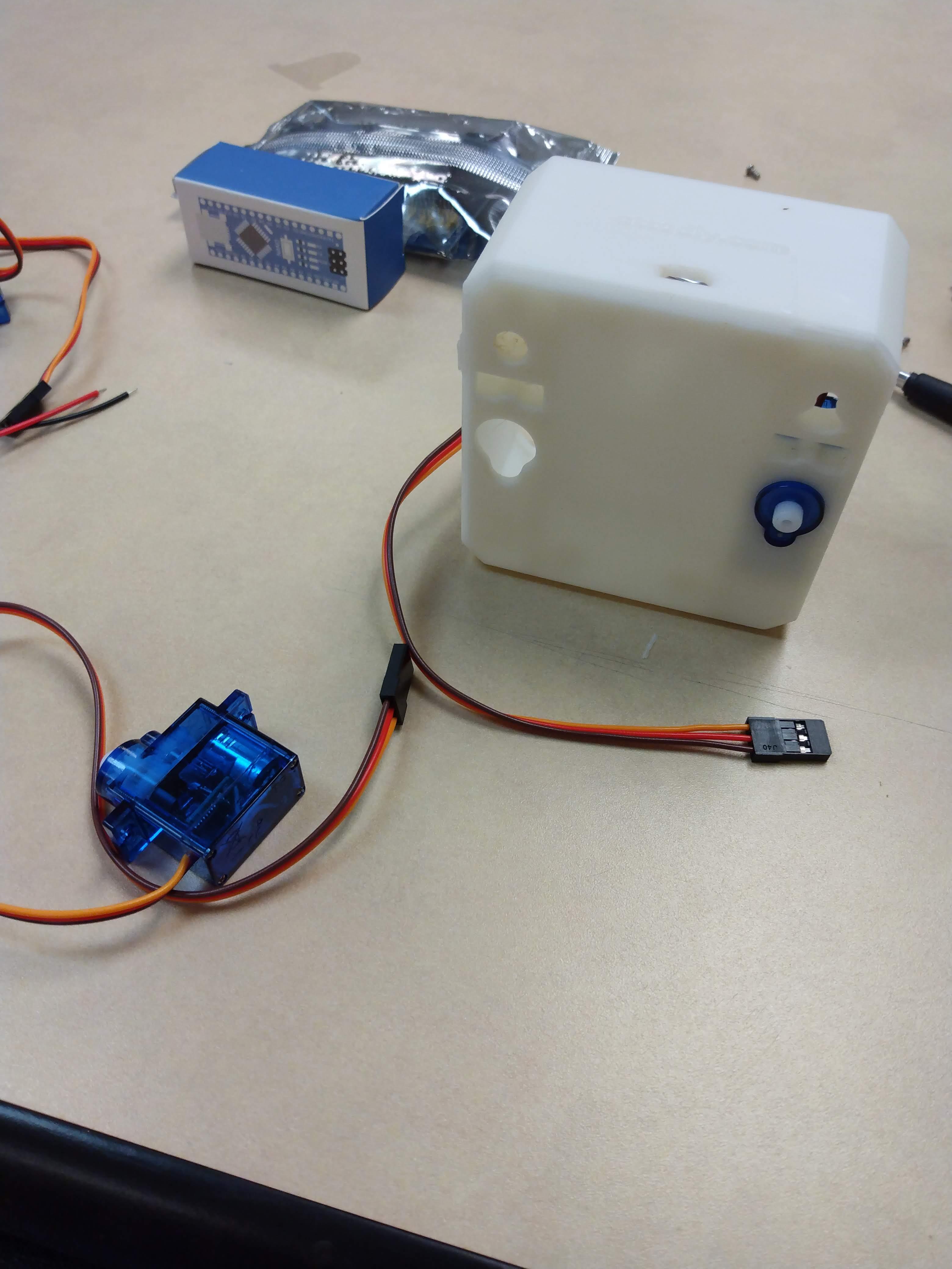
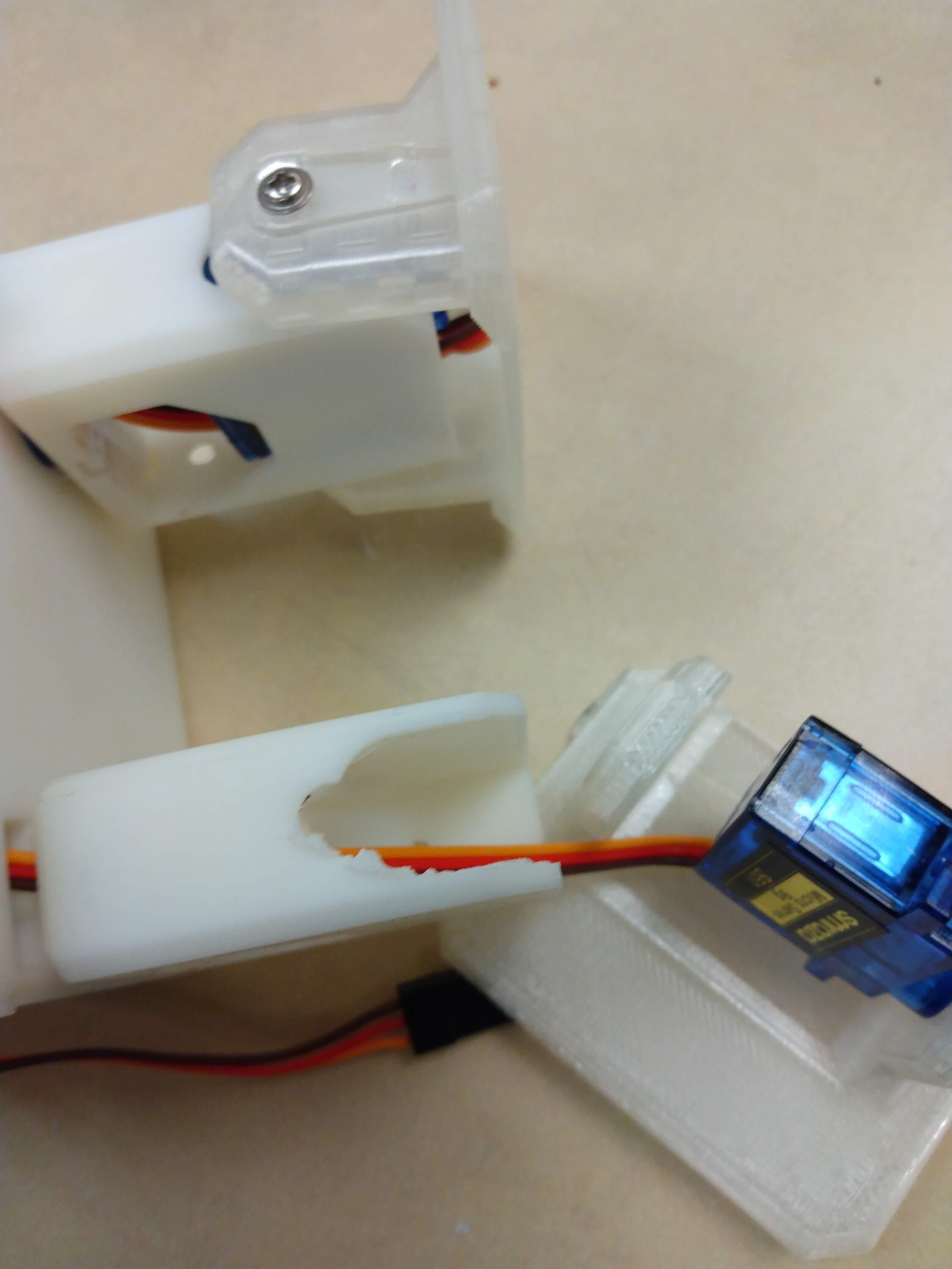
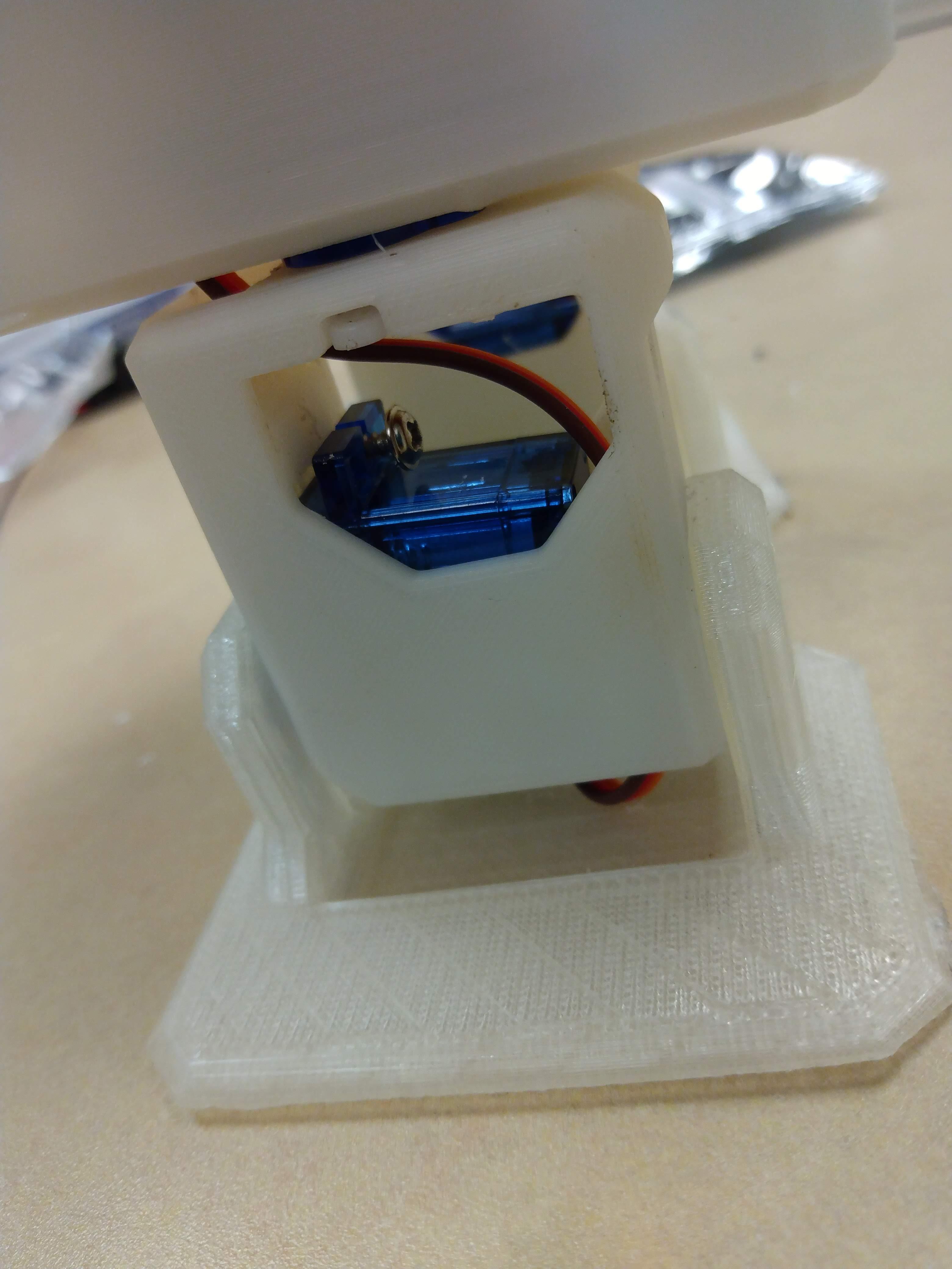
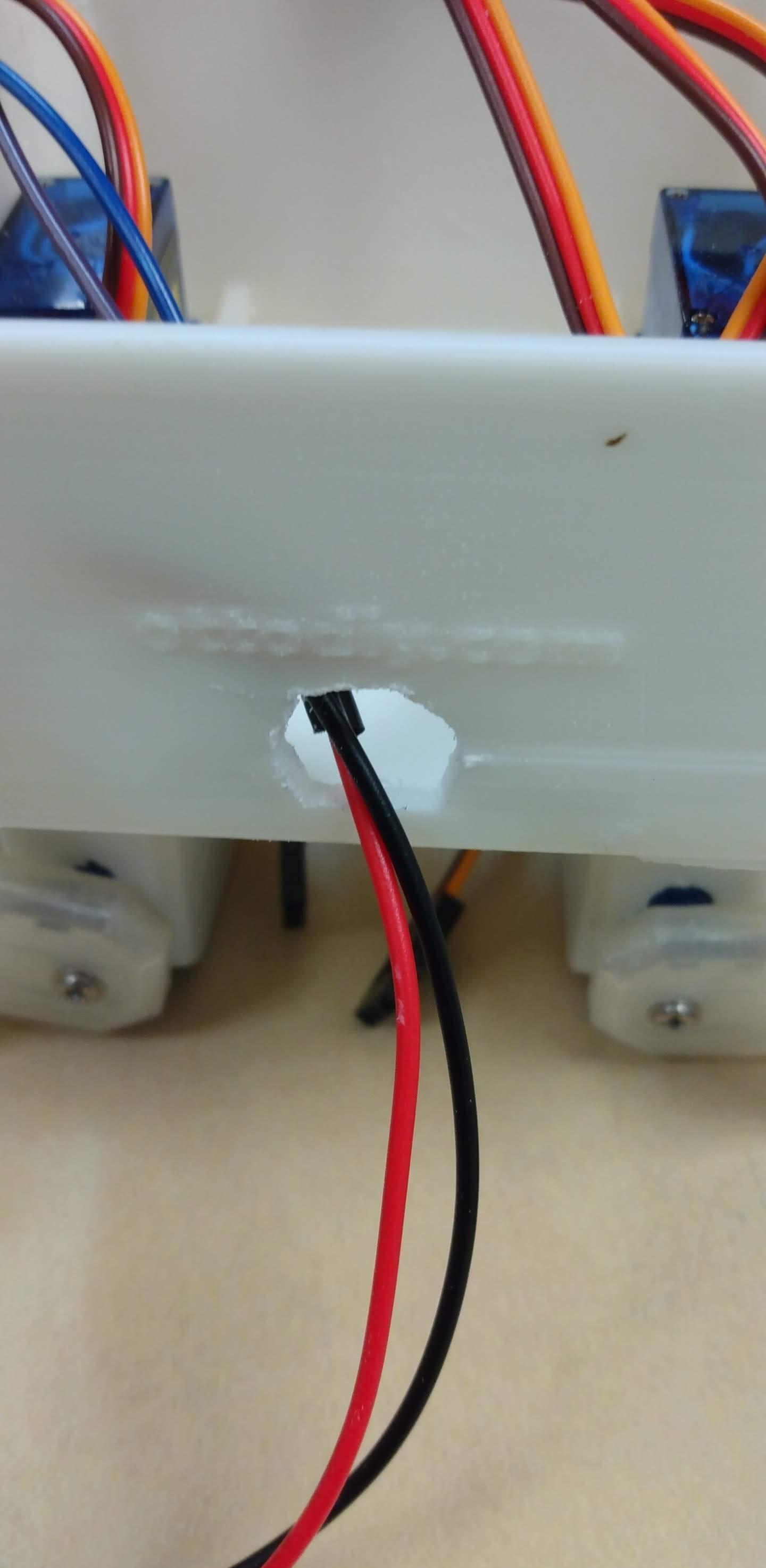
Fit Wires Through Slits on Foot and Slide Through Bottom Chassis
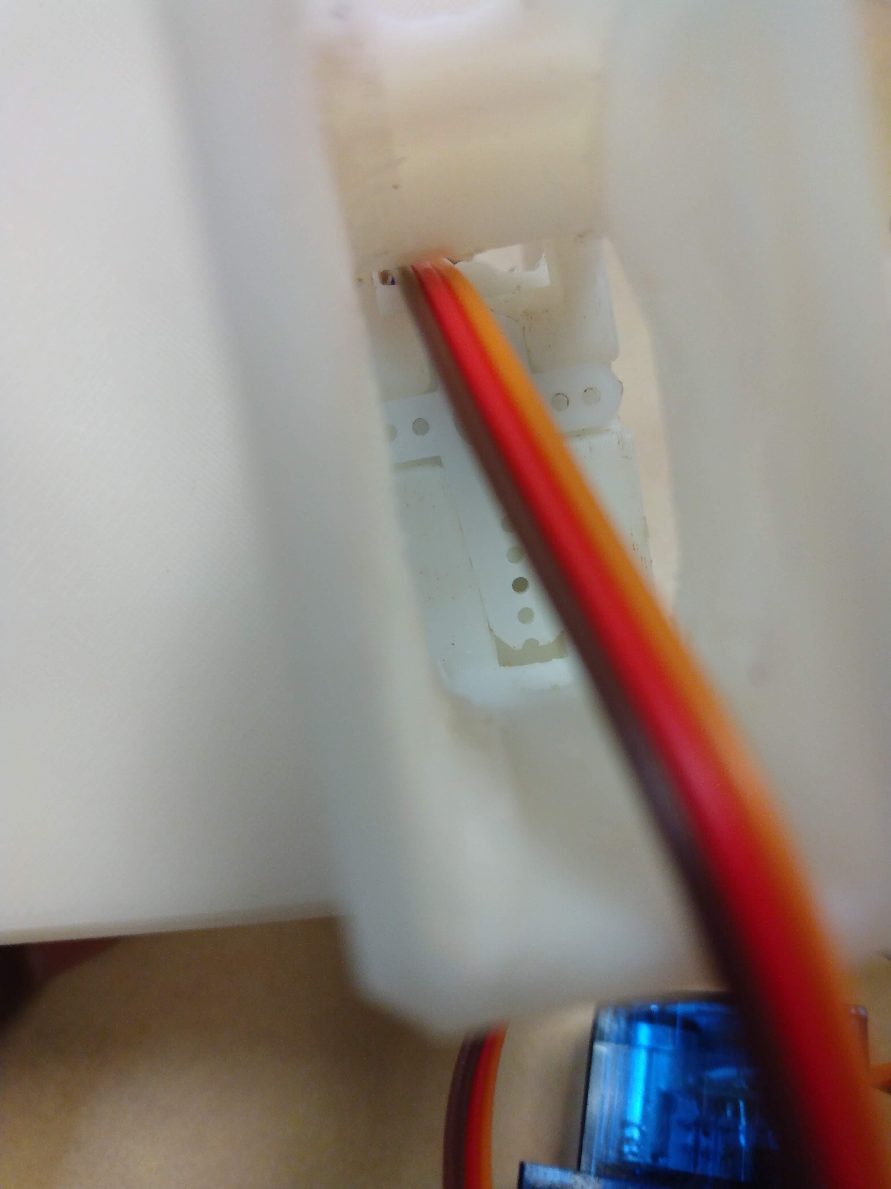
Once you've gotten everything where it should be, slide the wires through the appropriate
Attach Feet to Leg and Screw Them Together
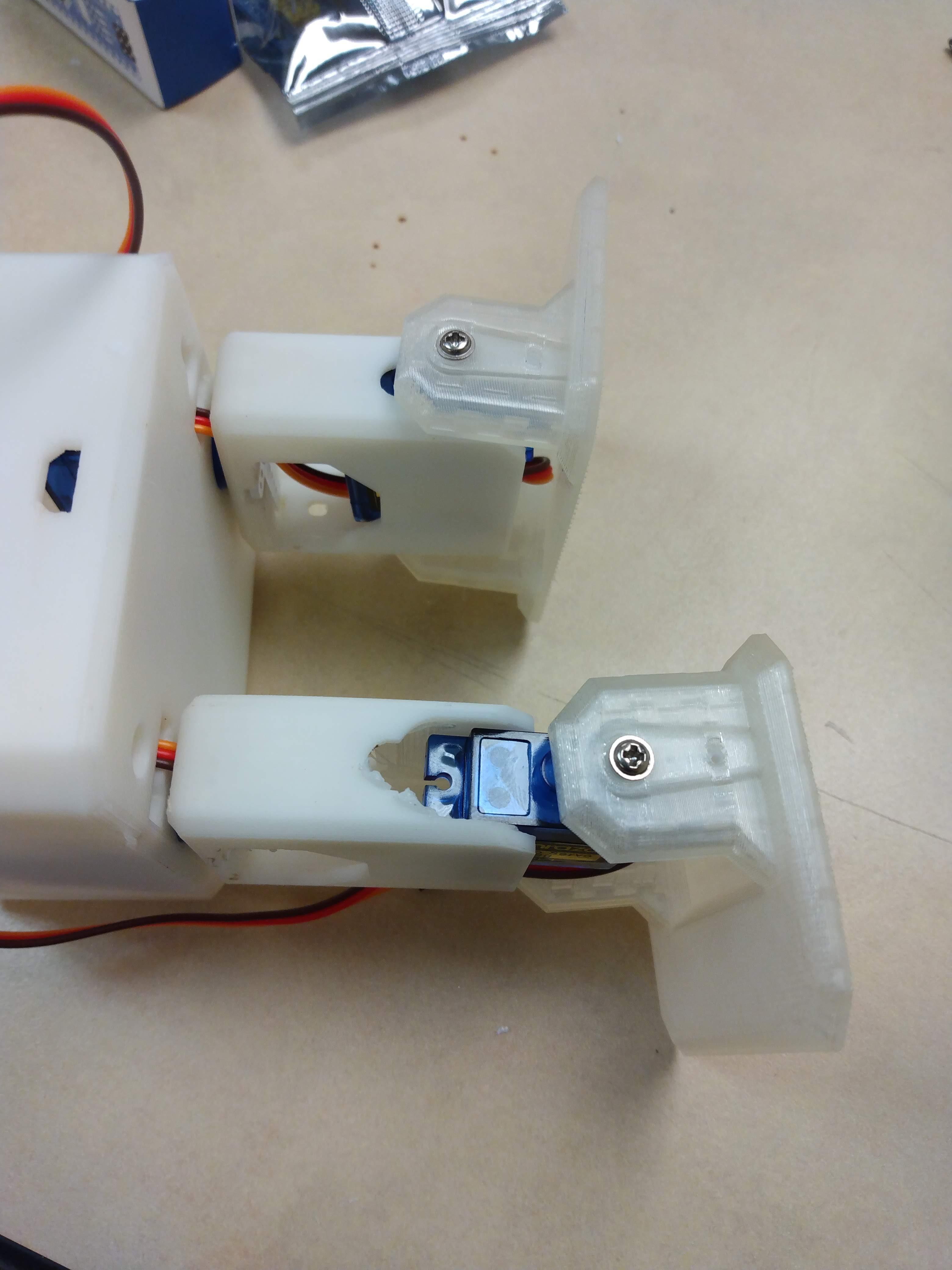
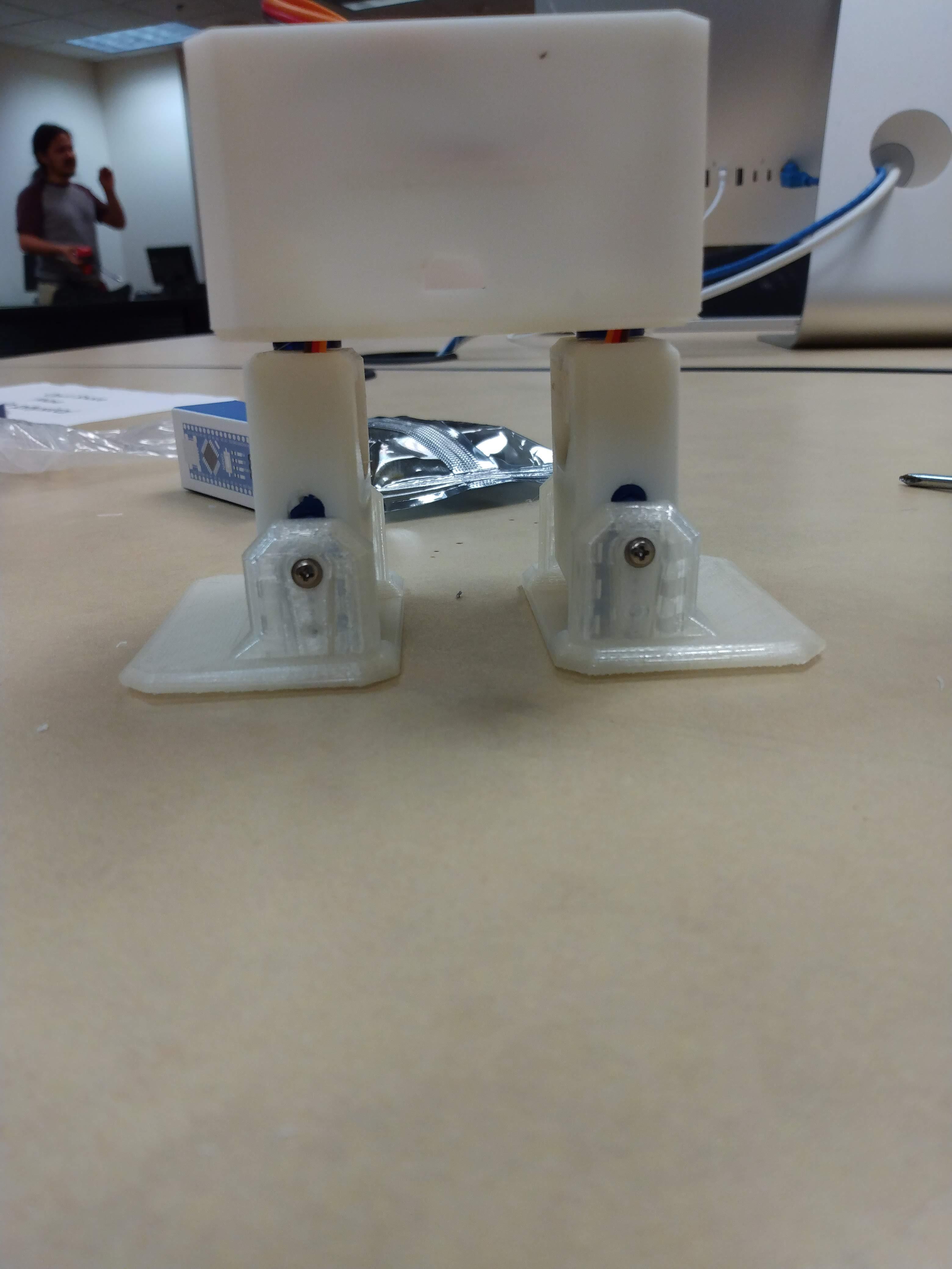
Once you've finished both separately, attach both parts together and screw them together.
As stated before tightly but not tight enough to break the plastic/filament.
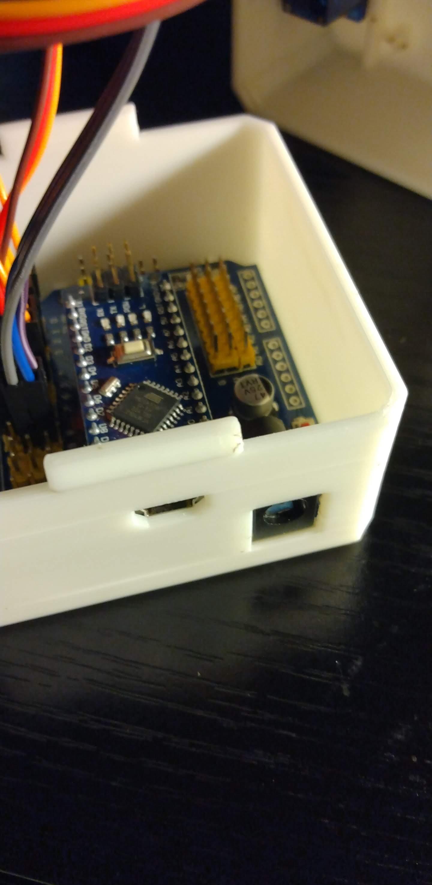
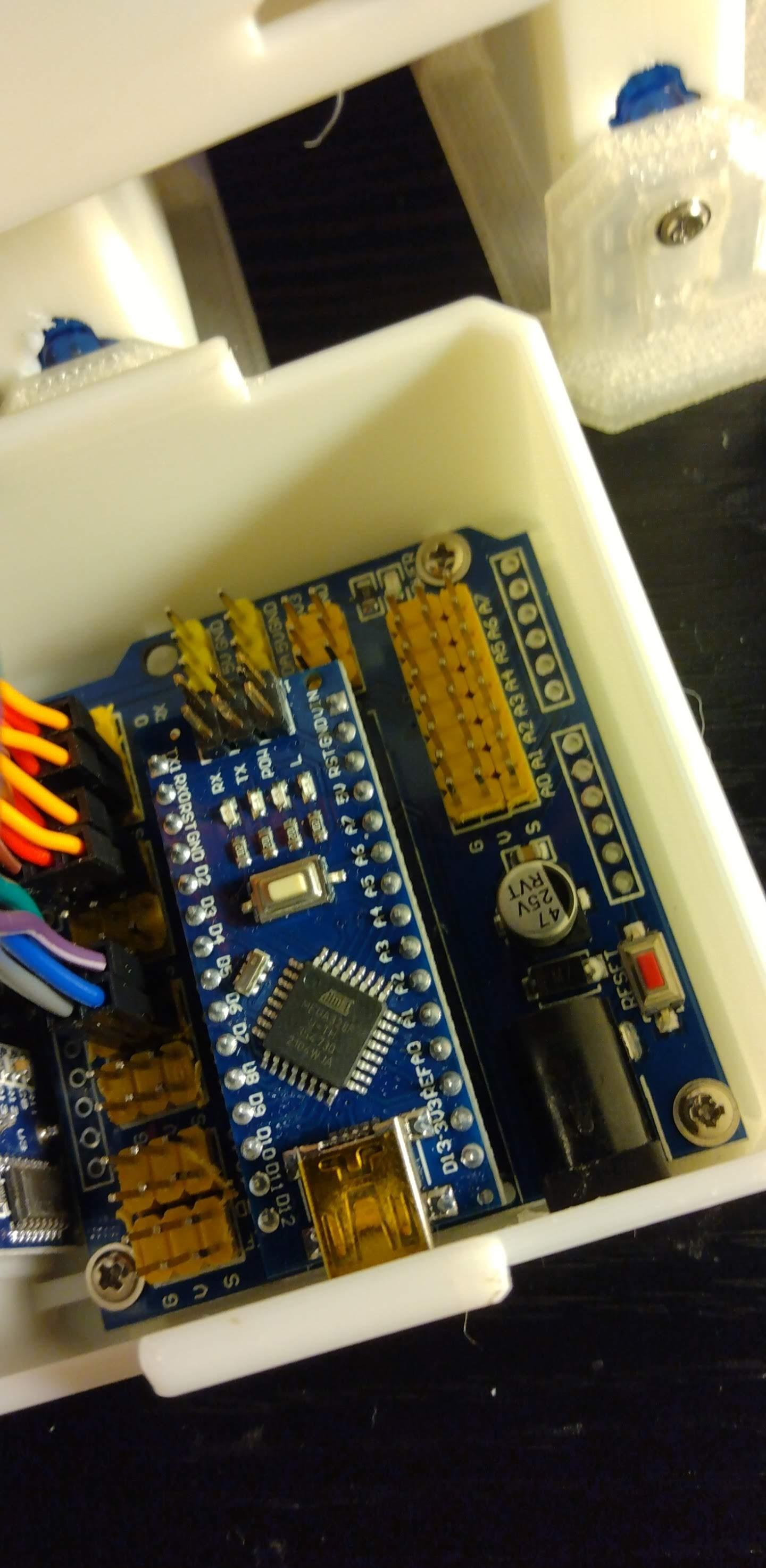
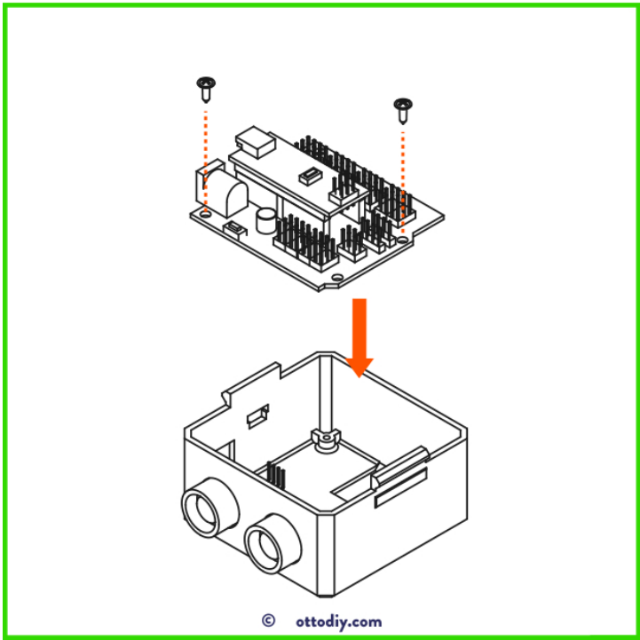
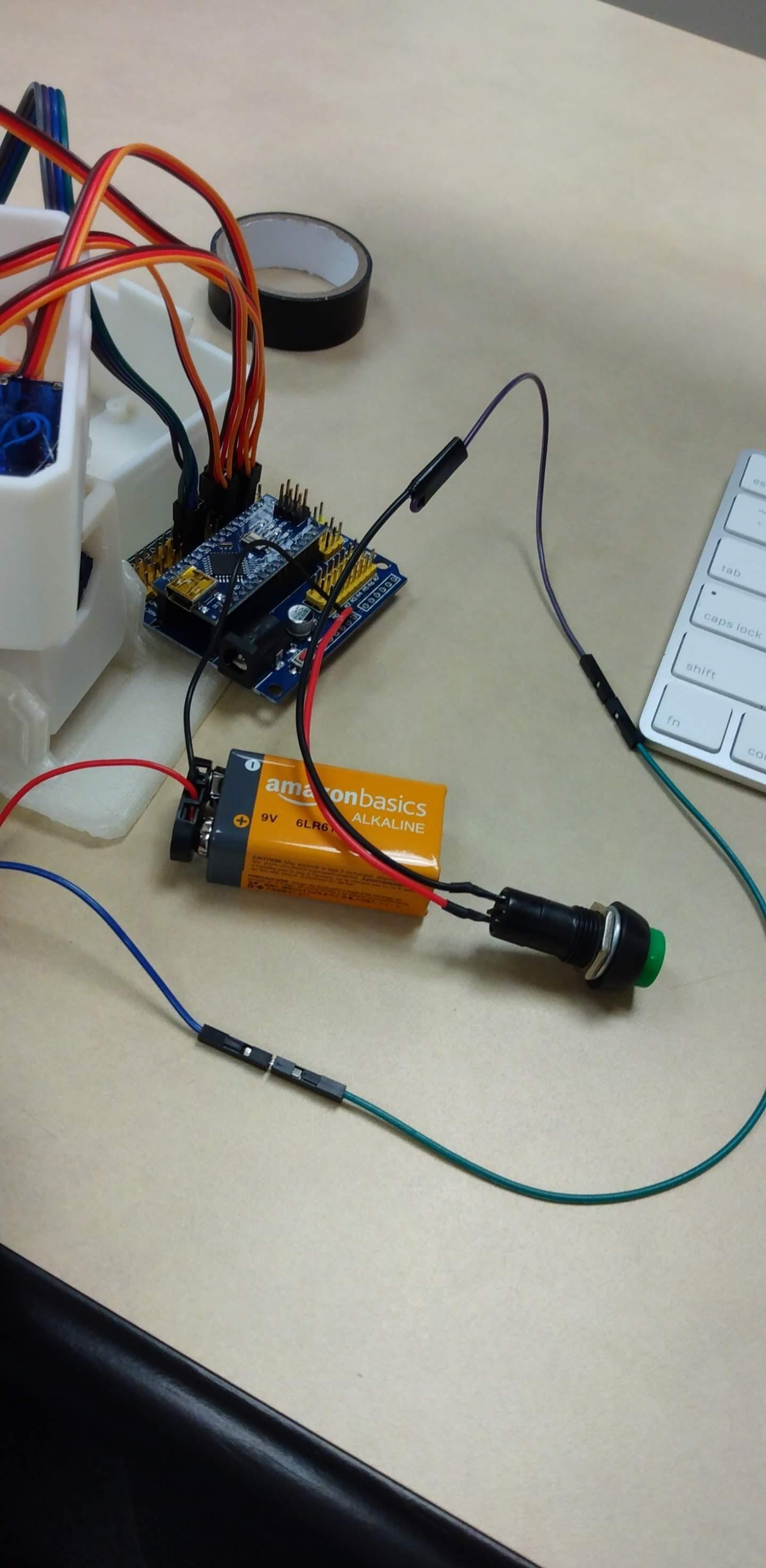
Prepare Microcontroller and Nano I/o Shield
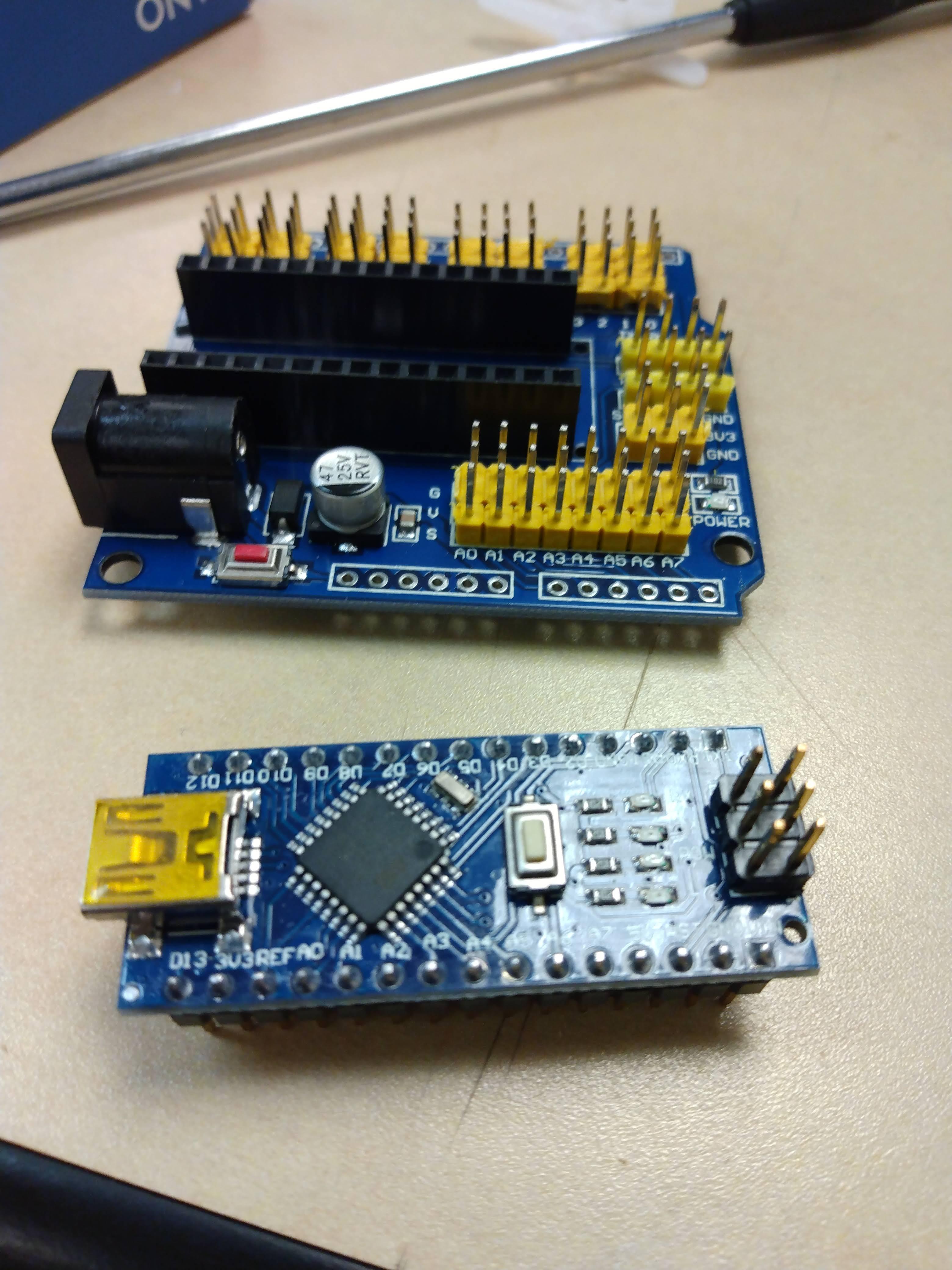
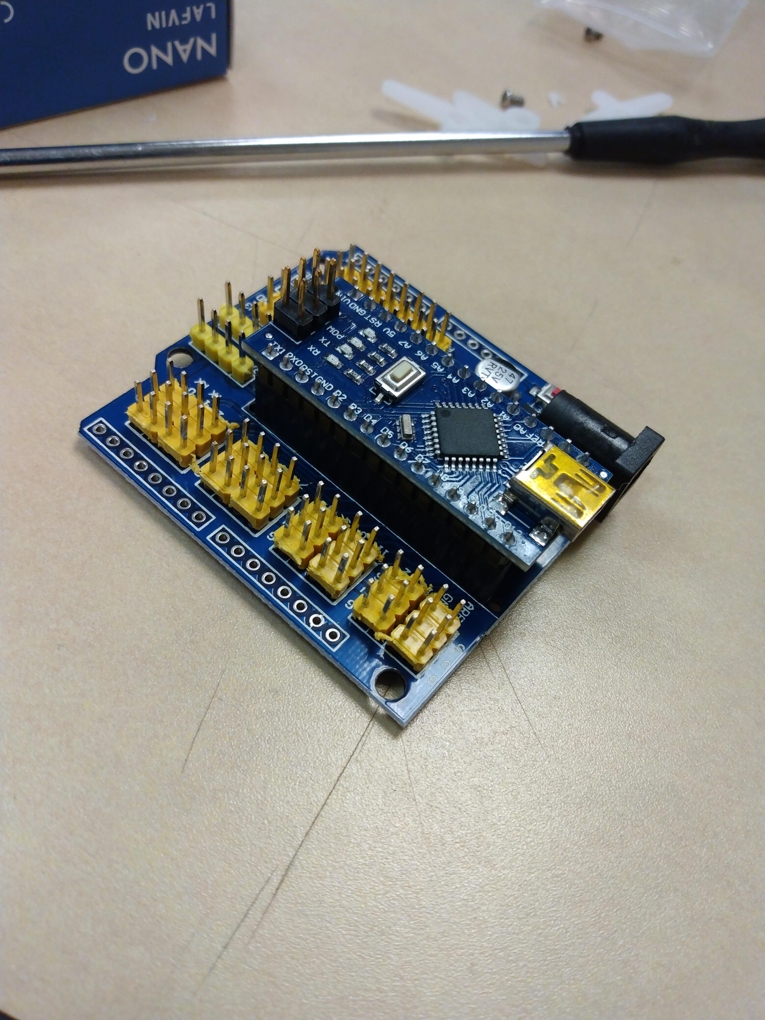
These pieces will go together to store the data and programming for your Otto robot.
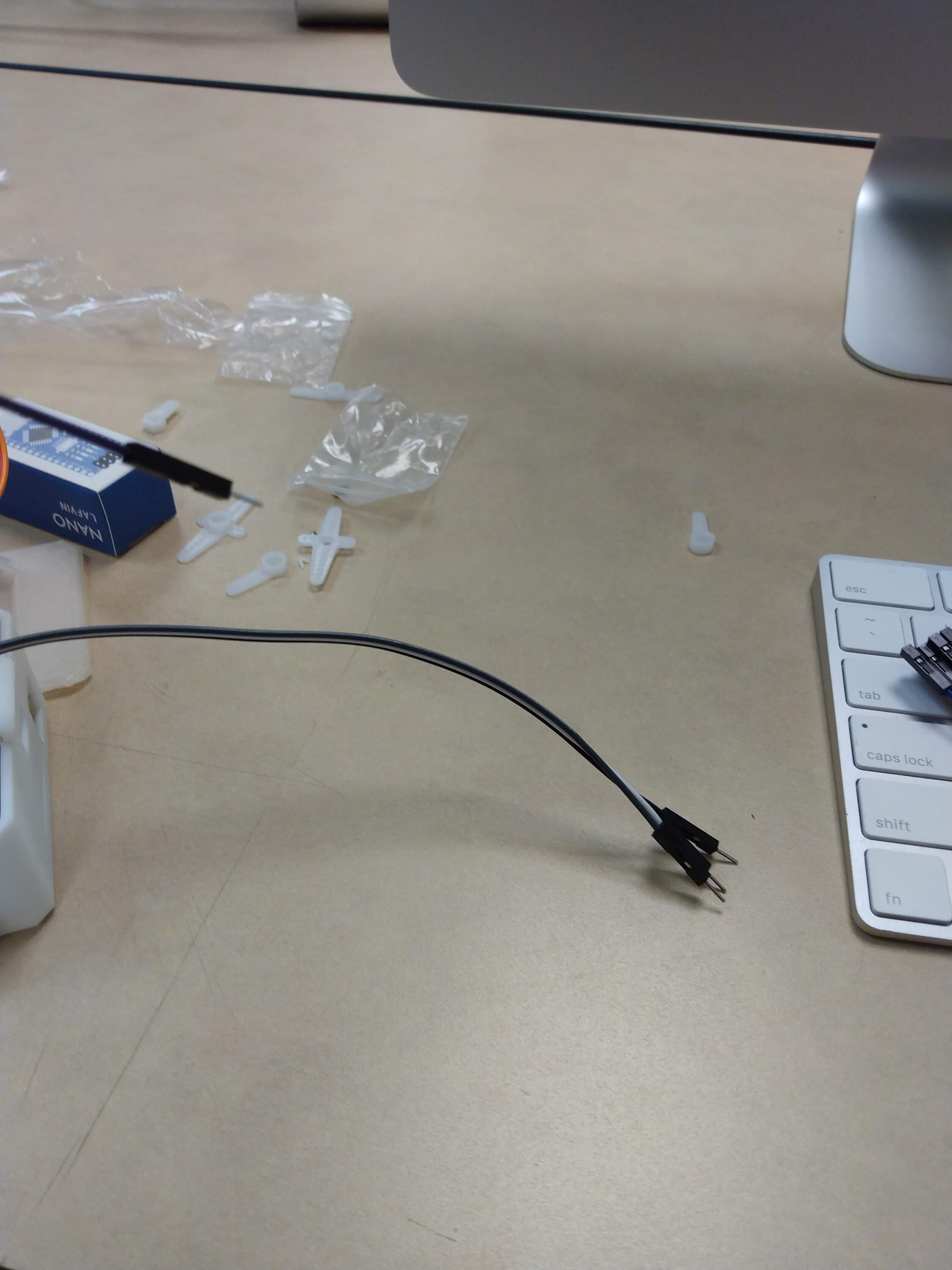
Put Servo Wires on First
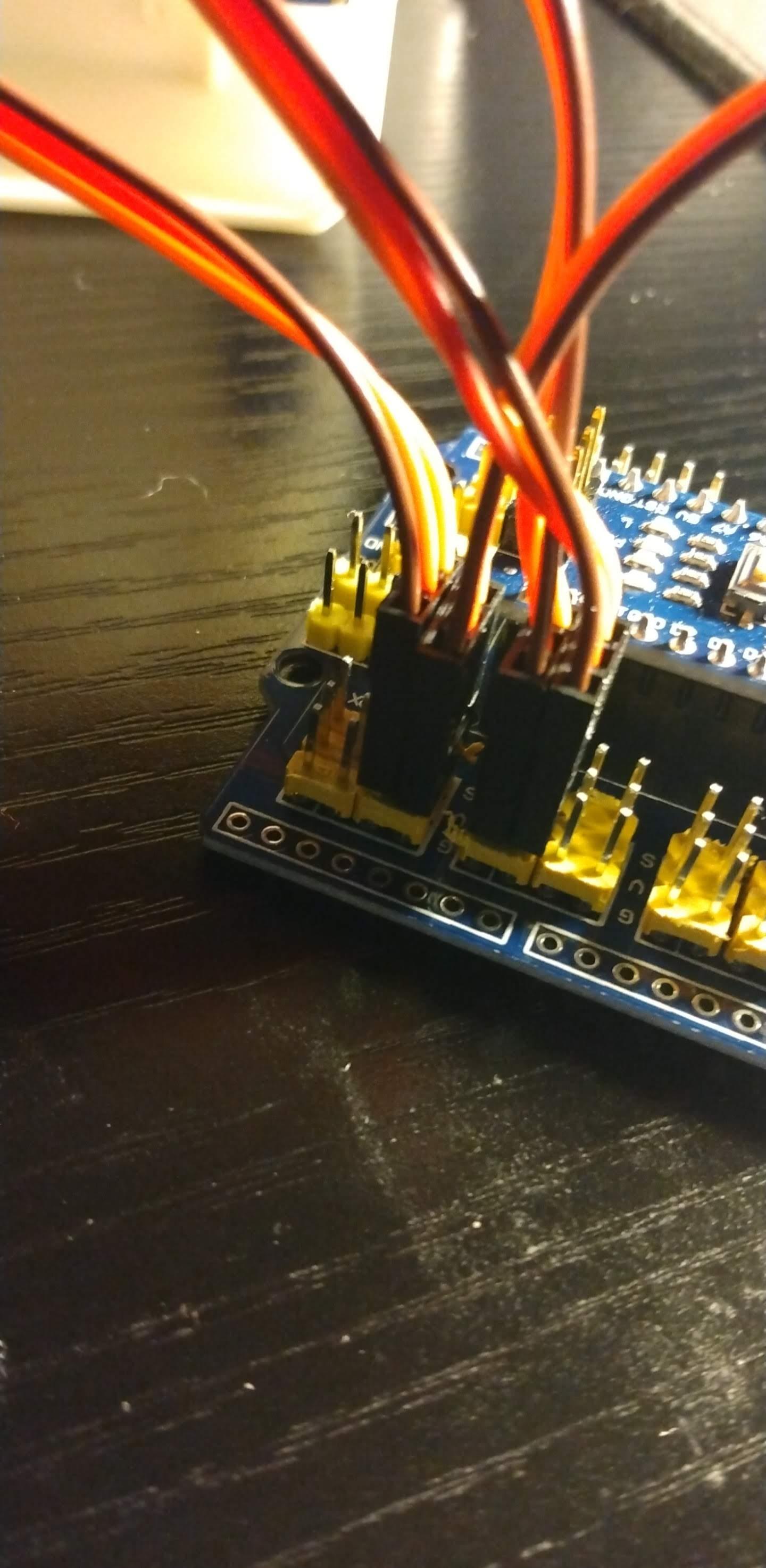
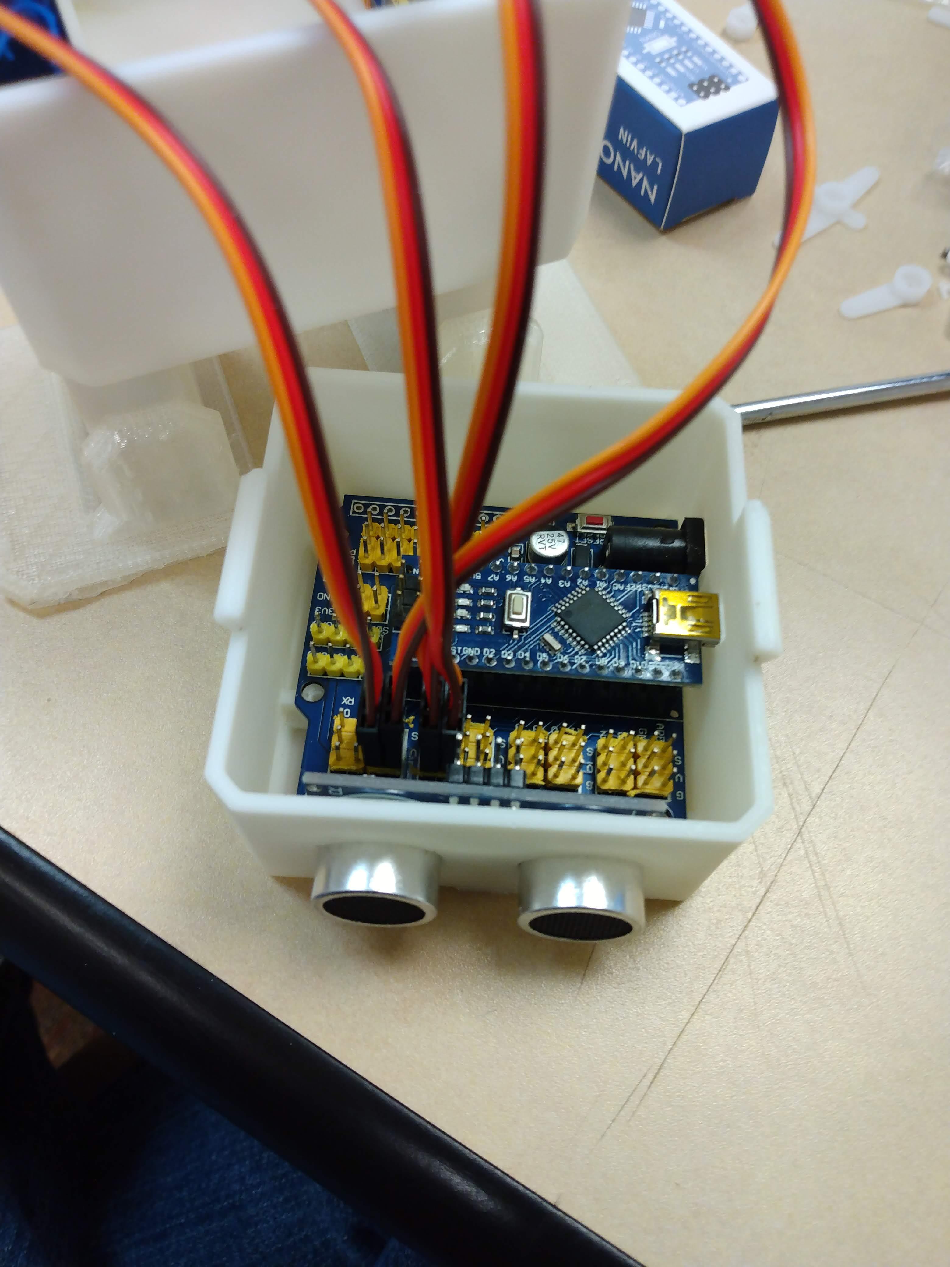
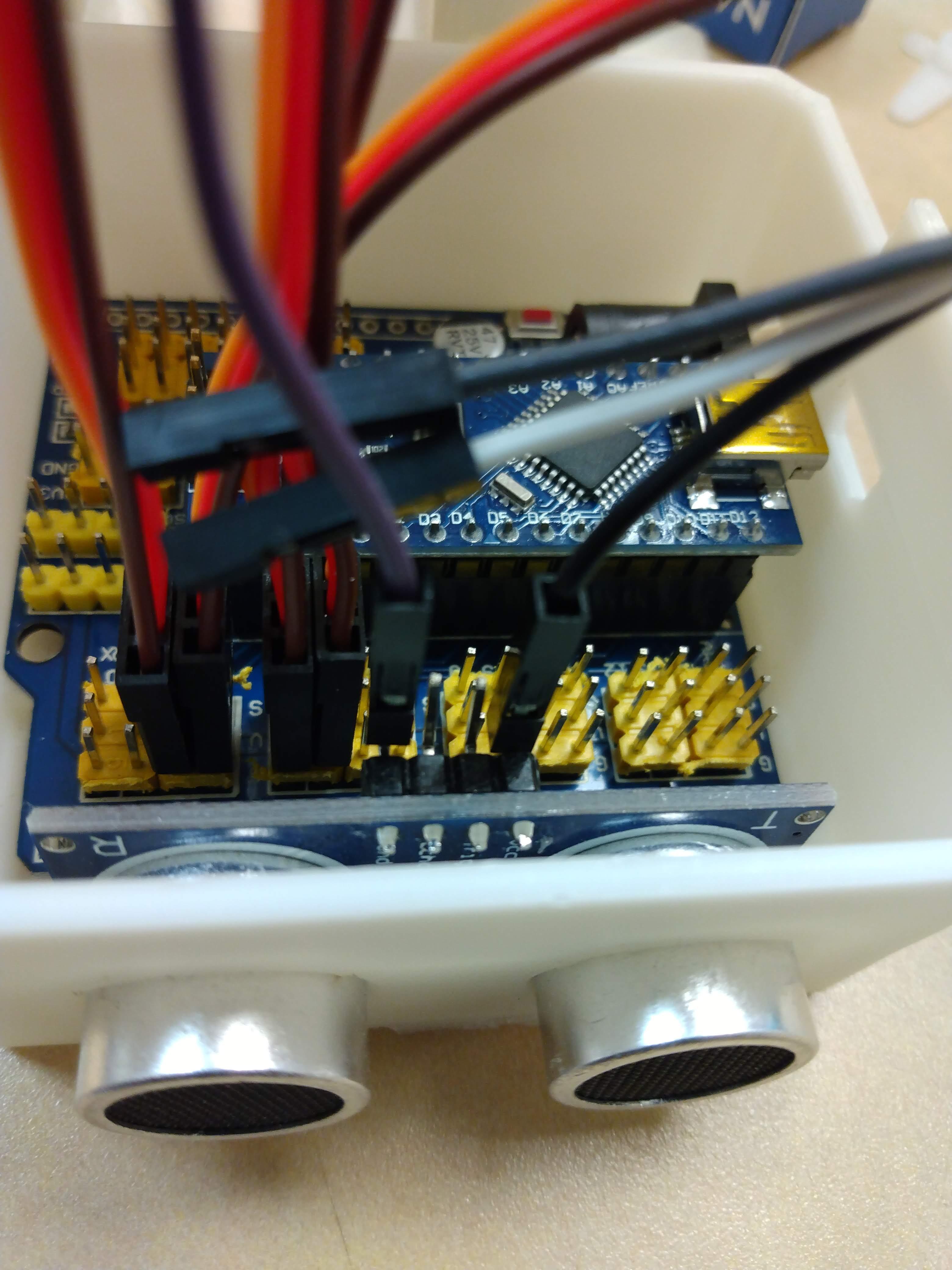

Just for clarity's sake, remember to put the brown or identical wires towards the center of the board.
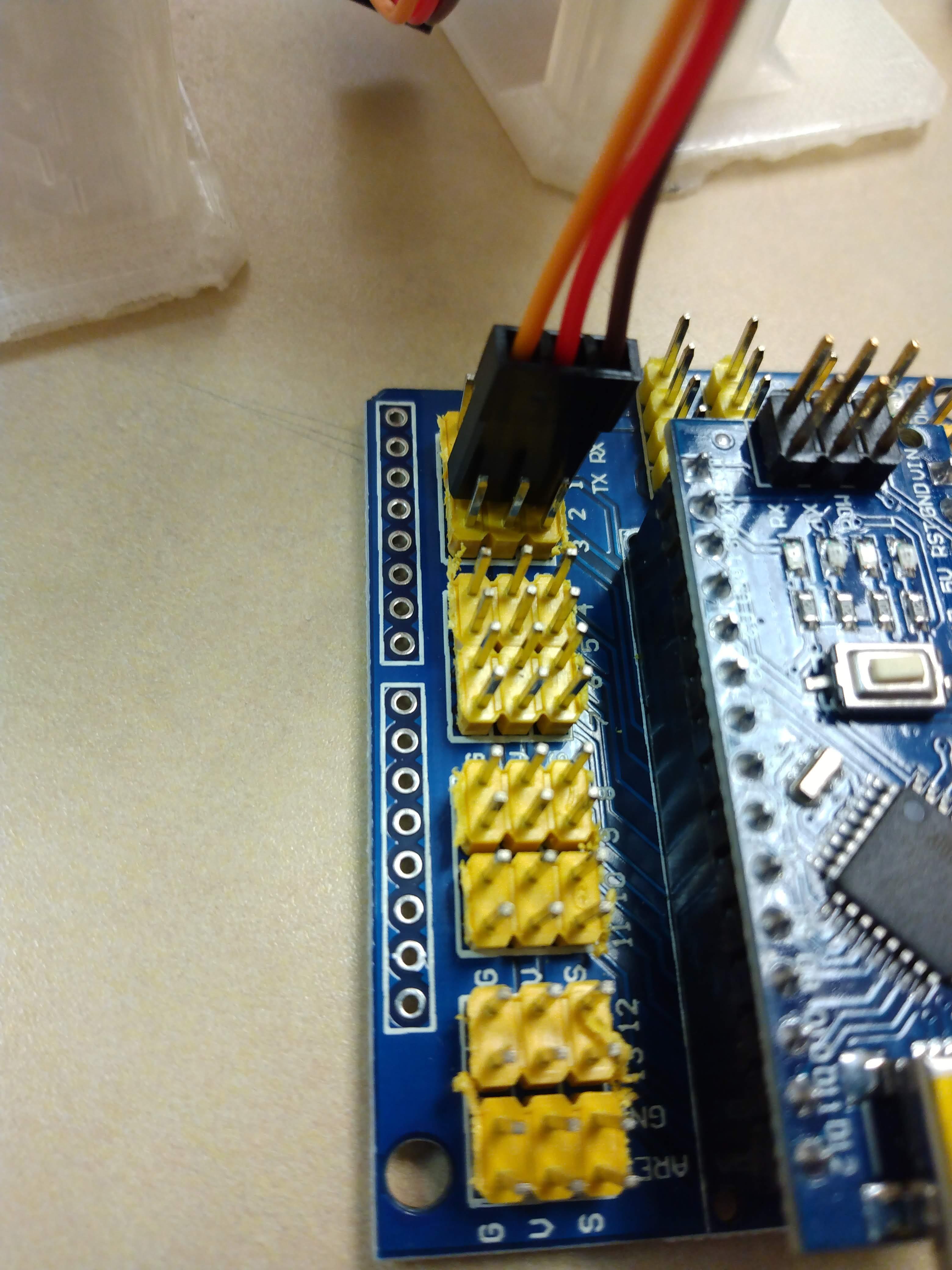
Put Sensor Wires in Correct Places
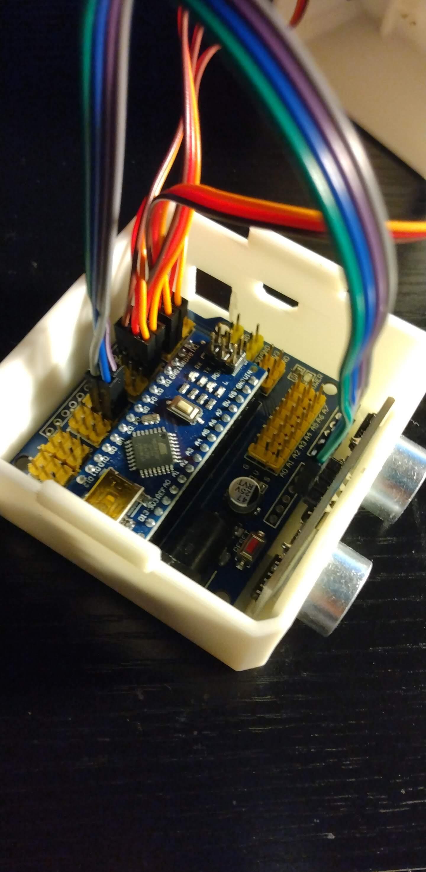
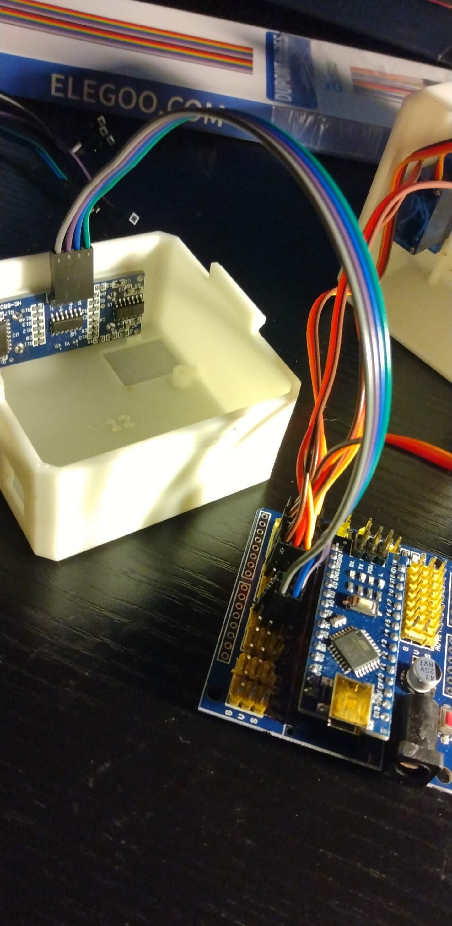
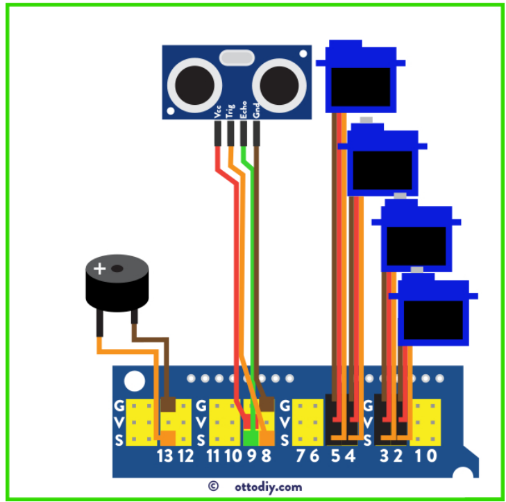
Follow the diagram and plug the wires in at the correct places.
and finally screw down the microcontroller to the top of the robot
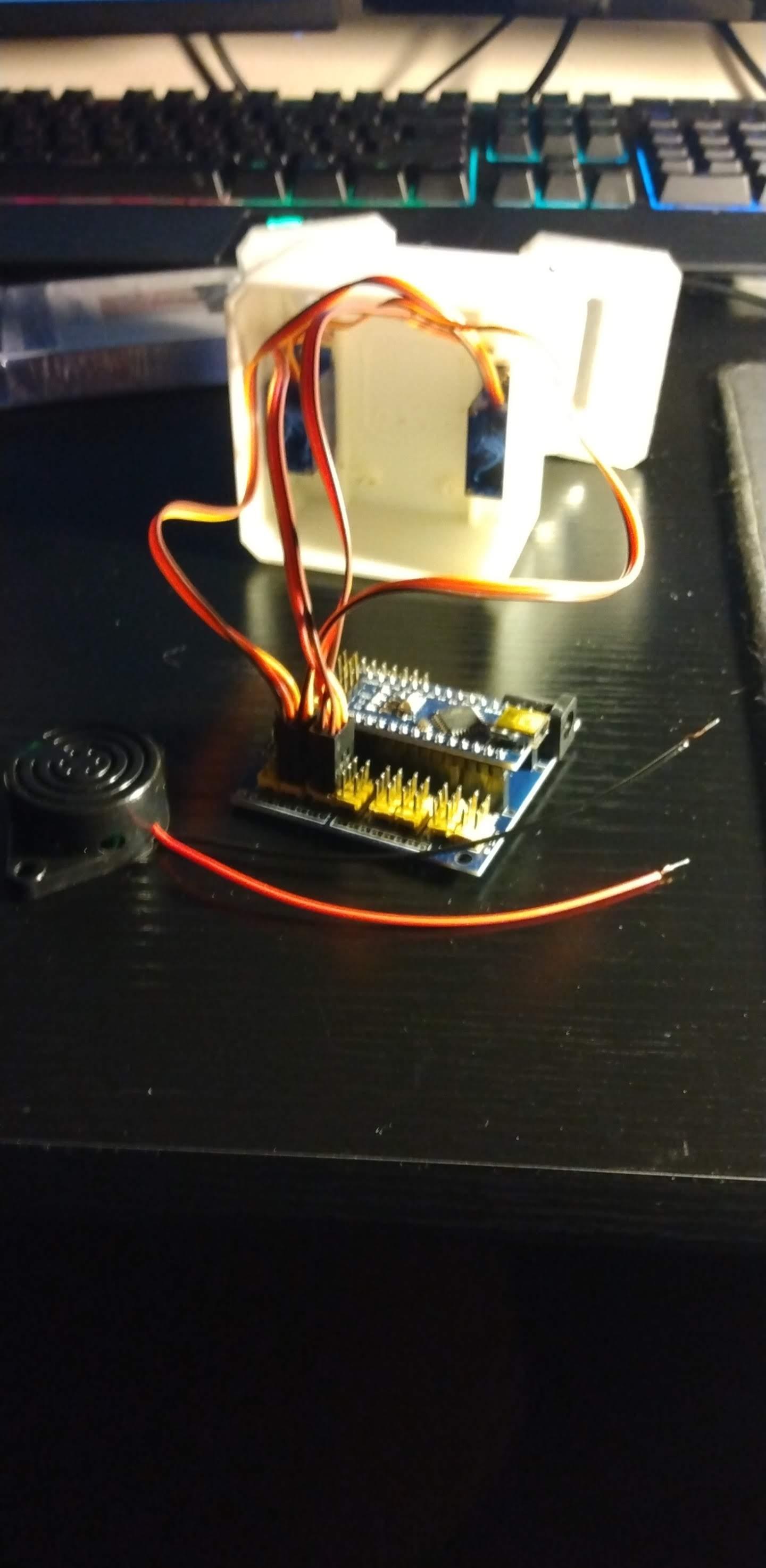
Make Sure to Plug in Buzzer
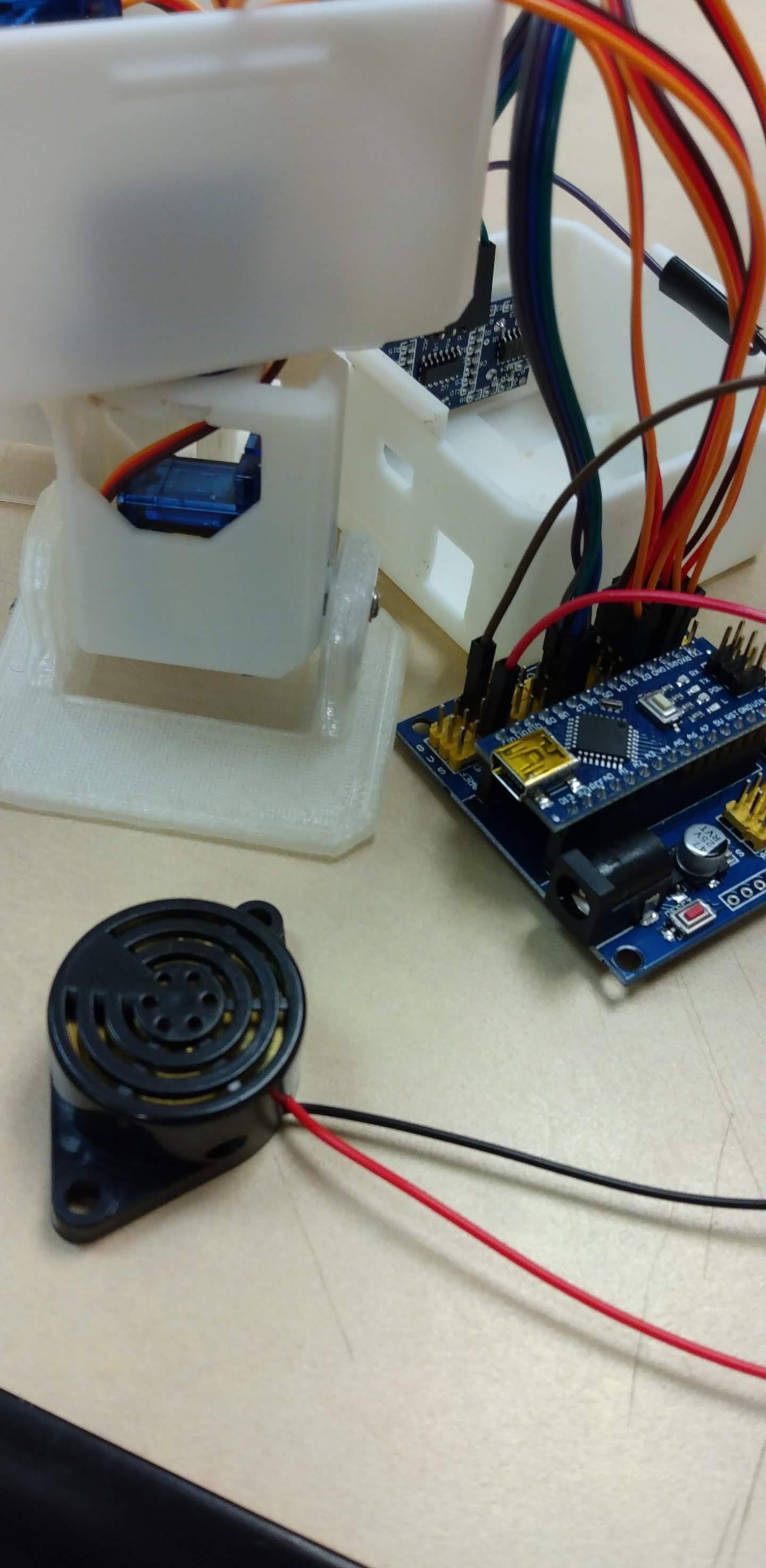

(Optional): If your buzzer does not have a female end similar to the diagram.
Splice the end of the wires with another pair of female end wires and your buzzer should work fine.
Plug and Place Power Button
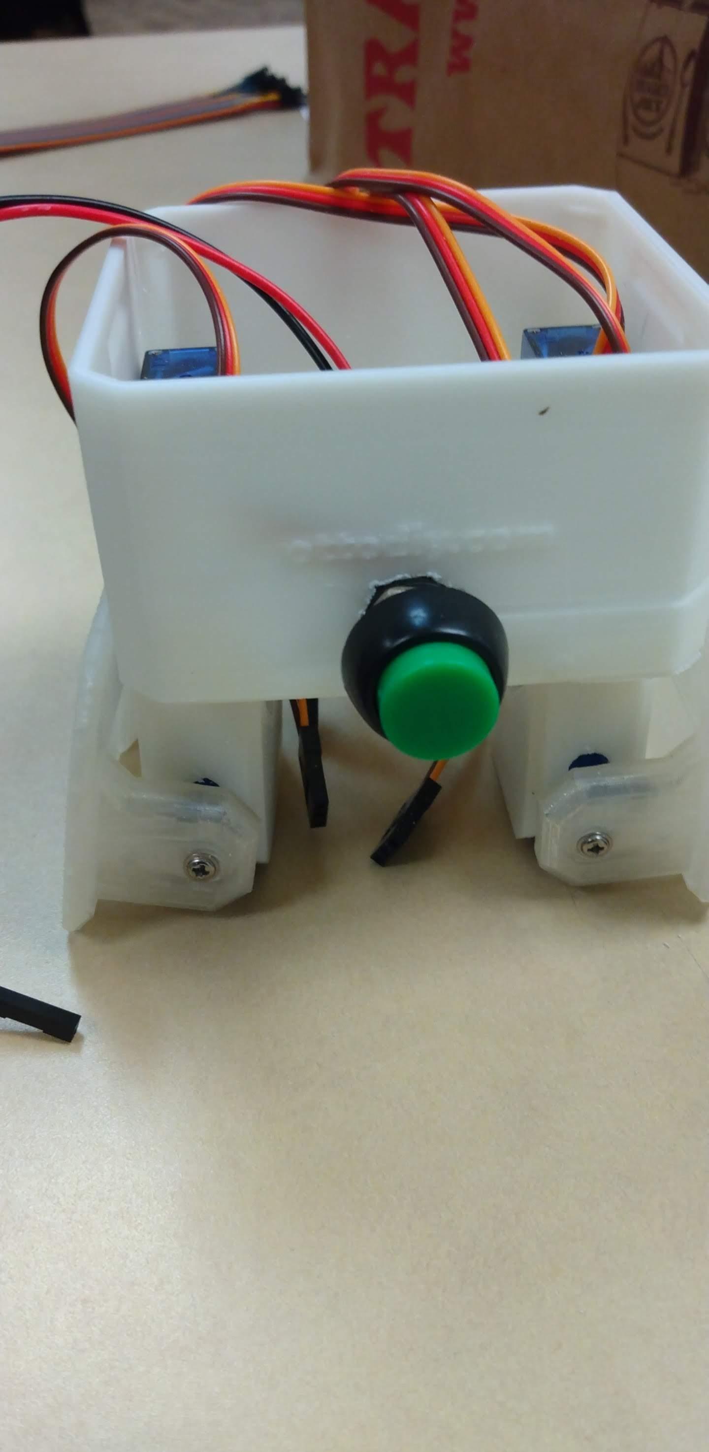
This step has multiple checks to get complete.
If your hole for the power button is not big enough, make sure to file it down.
If it's just right, make sure that it can at least fit comfortably within the chassis.
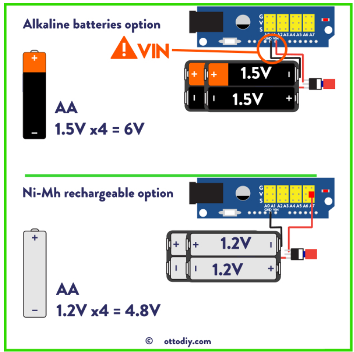
Everything should be referenced back to the diagram provided on choice of battery.
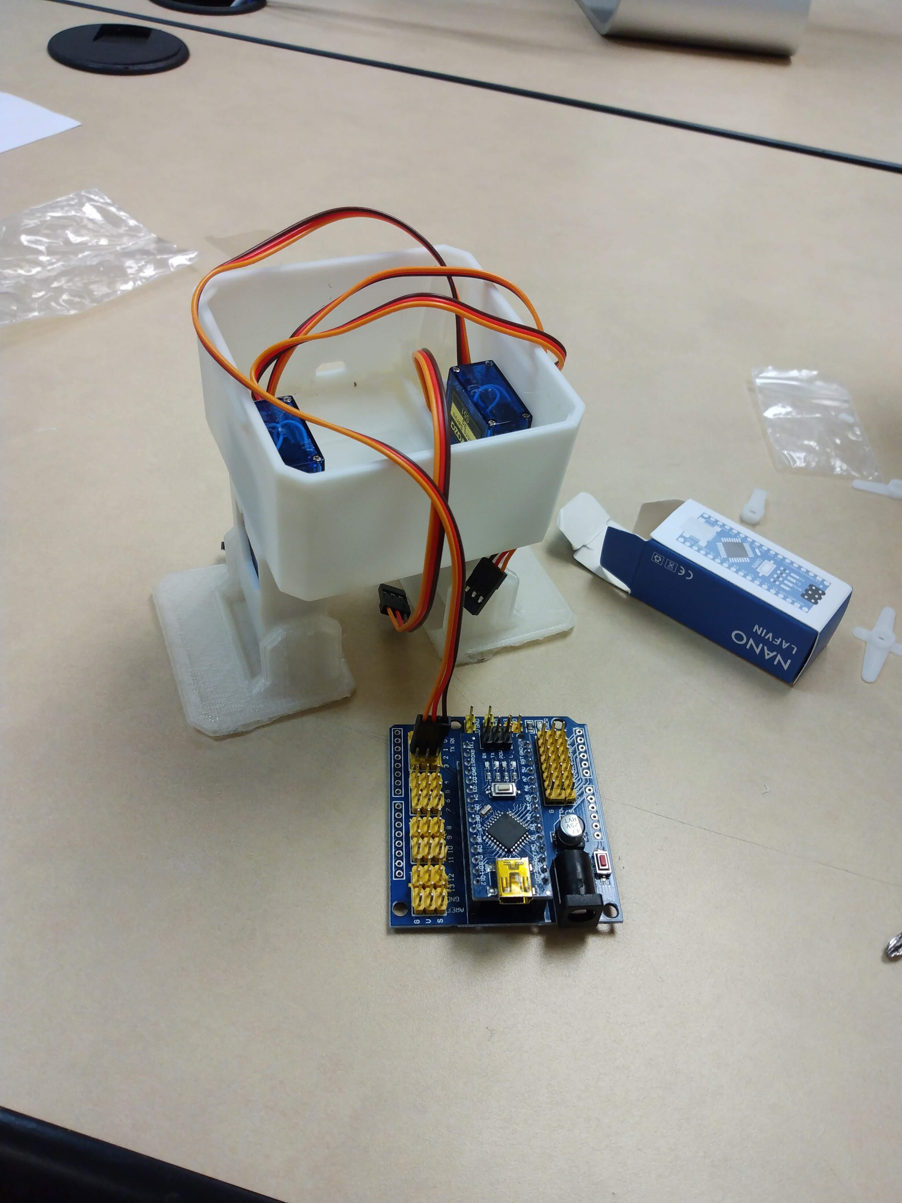
Completion
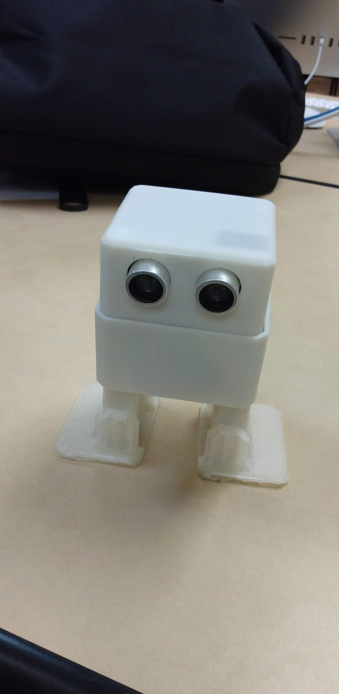
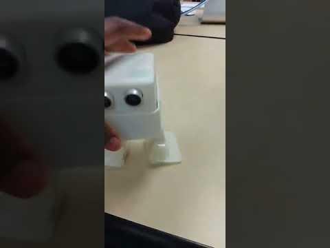
With both parts of Otto complete and ready to go.
All you need is to program Otto with commands via Arduino, and you're ready to watch your little robot dance.