Orbiting Camera Robot Controlled With Your Fists
by Pave Workshop in Workshop > Tools
13293 Views, 200 Favorites, 0 Comments
Orbiting Camera Robot Controlled With Your Fists

If the build video won't load try following this link to Youtube.
Orbital camera rig
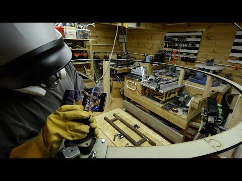
This is an orbiting camera robot that you can control with your fists.
Pretty much every project of mine builds on the last one. The main response I got from my latest build, an automated filmmaking robot was 'cool, but what would you actually use it for?' It's a good point, and although I'm usually only ever interested in making demos, this time I thought I would keep this critiscm in mind, and try and apply my technical experiments to something a bit more functional.
I'm always setting up shots in the workshop, and I'm obessed with interesting cinematography, so I had an orbiting shot like this one in mind for a while. For a long time I've also been fascinated by the idea of creating a smarter workshop environment, and this is one of the tools I feel would be super useful for me getting towards that concept. I want to be able to put more focus into the making process instead of the documenting as I build. The solution I found is to automate things; remotely controlling your camera from where you're standing so you don't ever have to be behind it.
With the setup as it is, there are two possible interactions. You can tell the camera to start/stop moving around in you in a certain direction, or you can 'grab' the camera and move it to a specific location around the ring.
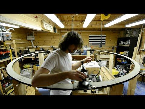
The ring itself is made up of 8 sections, so you can also operate the camera on a single section, or along an arc-shaped track, rather than an entire ring. It would also be possible to create a more complex and winding track with different kinds of sections put together.
Three components of the build
» Building a modular, slot-together rail system out of MDF.
» Making a stepper-driven carriage to transport the camera.
» Writing code to control a stepper motor with your hands.
Making low cost interactive motion systems
As usual, I'm not expecting people will want to duplicate this setup exactly, and I would actually encourage you not to! I'm very aware that not many people have access to a laser cutter either, which I used to build the frame for this. But I do hope that it spurs on some ideas for something cool.
Feedback I got about the last one was the cost of the Kinect V2, so this time I learnt some new content to get gestures working exclusively with the Kinect V1.
The challenge of wooden mechanisms
The 'low cost' aspect of this is really the fact that it uses flat-packed wooden sections and no metal whatsoever. I know that aluminium extrusion and linear bearings exist, and are the go-to for motion systems. I also now realise that wooden gear teeth are pretty hard to do well. But I do think there is merit in being frugal. Rejecting the easy solution for something that challenges you to make it work anyway is exactly where ingenuity comes from. I happen to have access to a laser cutter but not a 3D printer, so designing machines that can be built exclusively from flat pack wooden panels is something I've been practicing for a long time now.
Supplies
Gesture control / motion tracking
» Kinect V1 (Xbox 360 Kinect + PC adapter)
For runners, carriages and other sliding mechanisms
» Standard 22mm skate bearings that fit (loosely) on an M8 bolt. Nice and cheap in bulk on Amazon.
For the drive
» Standard bipolar stepper motor.
» '9-42V stepper driver' on Amazon.
For construction
» Exclusively 9mm MDF.
It's a lot of fun working with this material. It's just about strong enough to build things on pretty much any scale and relatively cheaply too, and it can just about be laser cut on a standard 80W tube. It allows you to make any object in a flat pack fashion. It does create a fair bit of smoke and residue though.
Tip for laser cutting: given its thickness, focus the beam slightly below the surface of the material for a cleaner cut and narrower kerf on the bottom face.
The main thing to consider with MDF is that its biggest weakeness is delamination. It can withstand a surprising amount of impact if you use it right and put enough material support at boundaries and connections where parts meet. Otherwise, however, it will tear or fracture super easily. Much like 3D printing, you slowly get a sense of this, but it's an important consideration because often for flat pack you want to use a friction fit, where you hammer slatted parts together with a mallet, and you don't want to break parts on assembly. For fixings, you have to be careful with impact drivers that you don't try to overtighten screws as you fit them, because fibreboard is soft enough that you can suddenly get it to 'strip out' and make that screw channel unusable.
Designing for Sheet Material
I've attached the .dxf files if you do want to replicate it or just take a look at the cutting list.
Construction
This 'ring' is comprised of 8 slot-together sections that have gear teeth on the outer edge. They're 18mm thick, made up of two 9mm layers glued and stapled together. The ring has a diameter of 2500 mm.
Sheet material
When I'm designing things to be made out of sheet material, I'm heavy reliant on CAD. It helps me visualise how the layers will go together, test complex geometries like gear teeth, and save a lot of time and material by doing as much of the iteration as possible in a simulated environment.
A suggestion for an alternative, 'recipe' based, algorithmic CAD workflow
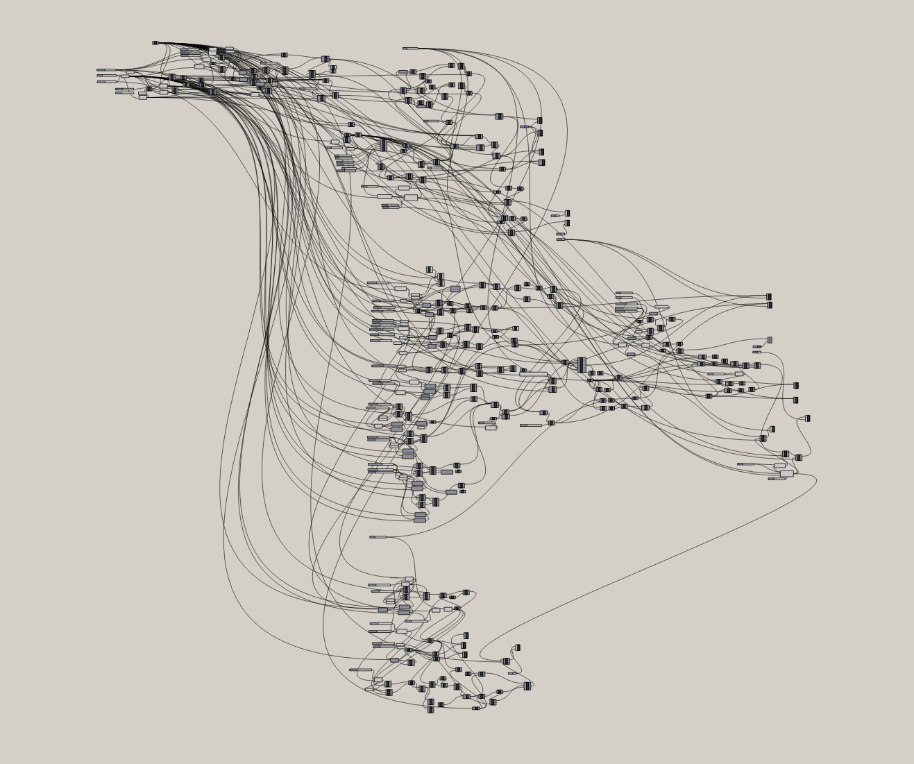
Even though it might initially make a lot of sense to prototype functional parts in something like Fusion 360, Solidworks or Sketchup, I now work exclusively in Grasshopper, which is a visual scripting interface for Rhino. It's usually used by architects for big structures but I find it to be an incredibly effective and versatile approach for designing parts, especially if you're used to writing code.
It's a lot slower of a design workflow, since you don't work in the normal way of drawing lines/circles/features with a mouse (you can work with sketched features and imported models though), but instead you essentially create mathematical definitions and building blocks that describe a geometry. The logic of your script is determined by the flow of connections between different kinds of nodes that do different things.
Every single feature of your model can be adjusted with sliders in real time. This also means you can reuse big chunks of logic between different but similar projects.
I personally find it a lot more freeing and intuitive than conventional engineering CAD environments. All that time you 'waste' in that initial phase creating a completely parameterised model, you get back when you come to cut out parts and something doesn't quite fit, or you want to radically alter something, but reuse some of the old features. You're able to just shift a slider or reconfigure a few nodes, and output the new part in less than a minute. I find other interfaces quite prohibitive for unusual parts like these.
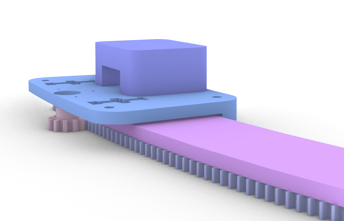
Rail system - sunken bearings and captive bolts
Since the carriage is very lightweight (designed only to hold a moble phone and not DSLR), I decided to go for a rail system where a track is 'gripped' by a pair of guide bearings either side, and then permitted to roll freely by two or three bearings on top which take the weight of the phone and carriage.
One of the big limitations you can probably see from using thick stacked layers rather than a 3D print, is that you are having to work much more in 2D than 3D. The way I got around this was by sinking the weight-carrying bearings and the bolt they're mounted on into the sheet itself, just enough that the bearing sticks out the bottom and enables the carriage to roll freely on the surface beneath. I created a cutout that matches the profile of a bolt with a bearing sandwiched between two washers, fine-tuning the tolerances so it fits snugly.
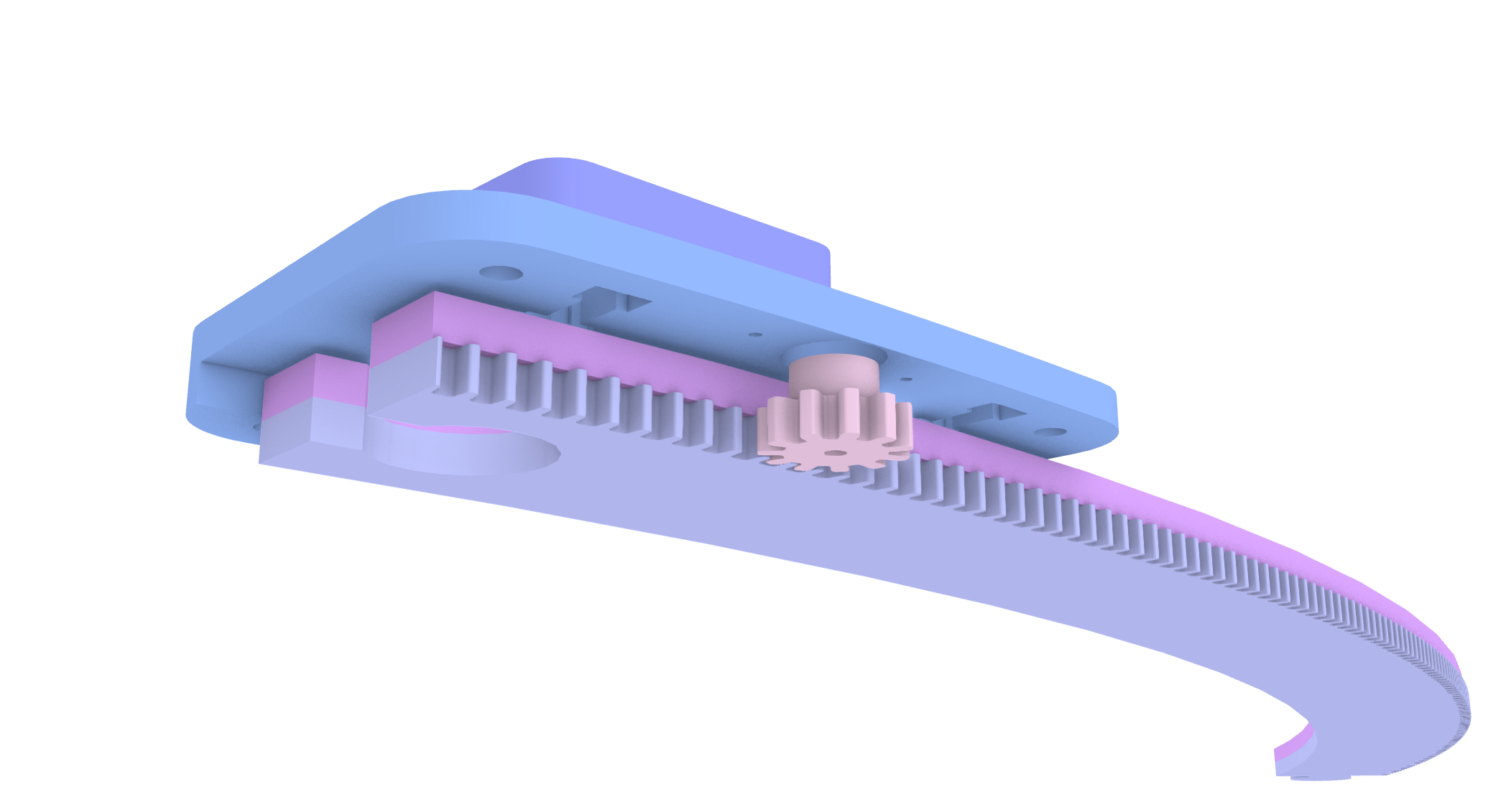
Wooden gear teeth
As far as I understand, selecting gear tooth size is a trade off: smaller teeth mean less friction and less backlash, but in something as soft as MDF, go too small and you risk creating teeth that will strip or at least wear out far too quickly. There are lots of tools to help you design a good tooth profile, but the theory is not actually that complicated to apply yourself too. One of the key principles is the pressure angle, which determines how square or pointed the gear teeth are. The other thing to consider is the size of the pinion gear. The larger it is, the more torque you'll be needing from the stepper motor to get it to rotate against the rack and drive the carriage.
Making Things Move
Setting up the drive
After mounting the stepper motor on the carriage, I added a pinion gear to the shaft and fine-tuned the tightness of the guide bearings so the carriage can roll smoothly, but with very little resistance, since the stepper motor has limited torque, even when using a 12V 4A power supply. I connected up an Arduino Mega 2560 and stepper driver to get things running.
Stepper drivers like the one I used give you a choice for the divisions of each step. Microstepping is a useful feature that allows you to move a stepper motor by fractional steps, but it also has knock-on effects for things like torque and the output speed. I found that using 4 microsteps gave me the best movement profile. I don't think there's a hard and fast rule here, just play around with the different modes and see what's best.
Control Protocol
I've attached the arduino sketch I wrote for this, 'orbital_motion_control.ino'. I essentially took the code from my automated camera rig, adapted it and added some improvements.
The appeal of using a stepper motor is that you can measure the distance it's travelling by counting the steps you've taken, and therefore know exactly where it is.
For the motor control, I began by building out my own stepper class. It allows you to abstract the low-level stepper driver signals with position targets: you set numerical destination which the stepper will automatically step to if it is not already there. I built off the code from my previous build, and although some of its functionality is not really necessary here, because I'm only controlling one stepper motor at a time, I prefer having low-level access to the stepper motor because it's more extensible for future developments.
Homing and positioning
This class also includes methods for handling things like a homing cycle with a limit switch. This means that every time you power on the rig, it will try to move around in one direction until it hits the switch, allowing you to have a consistent starting point each time, and know exactly where the camera is currently positioned around the ring. Importantly, too, if you decide to only use a few sections out of the circle, you want to ensure the carriage can only move within the correct extent and not continue moving off the edge. In order to do this, I determined the number of steps per section, and added a constant for the number of sections, which are multiplied together to find the extent in steps.
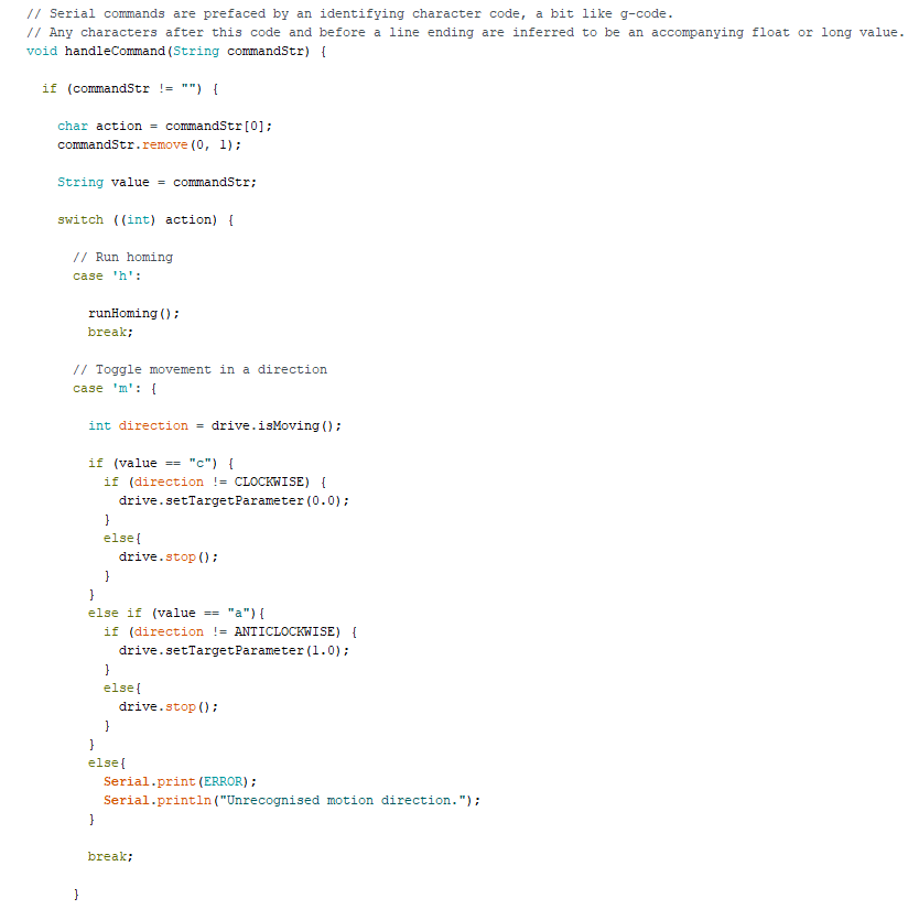
Knowing that I'd need to control the rig over USB, and send commands like 'start moving', 'move to specific position' or 'set speed', I created a crude command protocol, a bit like g-code. The reason for this is that I want to be able to send potentially hundreds of commands a second, so I want to ensure I am communicating efficiently. As you can see in the arduino code file, the way I decided to do this is by having an command-identifying character at the start of each message, and any remaining characters before the end of the line are parsed into an accompanying number or string value that informs that action. For example, if you send an 'm' and then 'a' or 'c', this will tell the rig to move, and the direction specified will be anticlockwise or clockwise respectively.
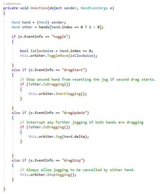
Movements are done in a toggle-based way. If the rig is already moving and you send a move command, it will stop moving. Equally if the rig is at idle, or going in the other direction, it will start moving, or change direction.
In order to handle absolute positioning of the camera, when you 'grab' and then 'drag' it, I first capture the current position of the carriage at the time of closing the fist (as well as cancelling any other movements), and then output subsequent motion of the hand as a distance delta from this start point that can be translated into an absolute position in steps that I can tell the carriage to move to.
Controlling Things With Your Hands
To get the position of the hands, and determine whether the fists are open or closed, I'm using a Kinect V1 sensor. It's slightly less intuitive and limited in its gesture recognition ability than Kinect V2, but less cost prohibitive.
The hand data is processed by my C# console app. This contains a serial class which deals with communication with the arduino and stepper motor over USB, and an interaction class which decides what commands to send to the rig based on what the hands are doing. The main logic is distinguishing between short 'clench' or 'toggle' events and 'grab and drag' events. This involves recording the position where the drag was started, and then continuously measuring the distance delta as you move your hand in either direction, which is translated into a position in steps to move to.
Working with interaction frames and Kinect V1
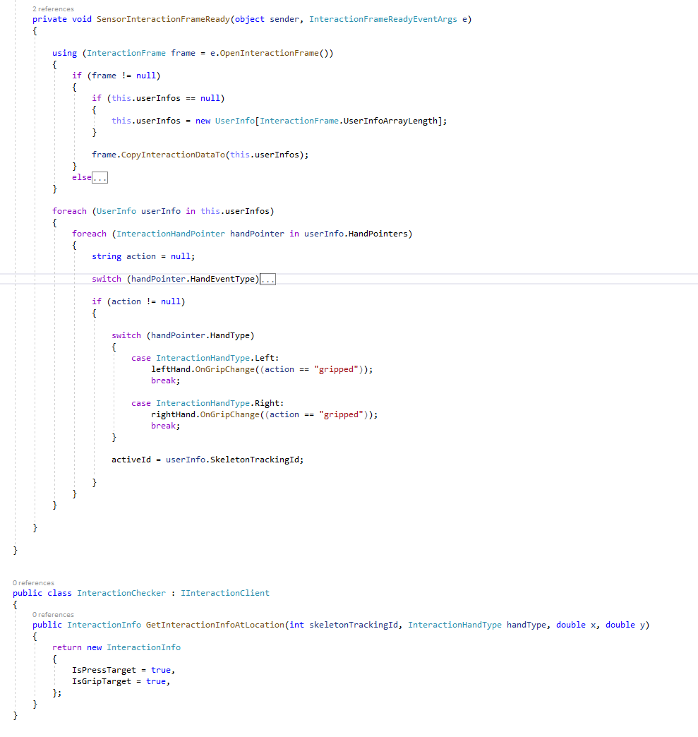
The Kinect API offers various different data streams to access different kinds of sensory information. You have to activate each stream if you want to work with that data. These streams include colour frames, depth frames, infrared frames and skeleton frames. If we just wanted the position of the hands, we could use the skeleton stream, looking for the positions of each hand joint. However we want some kind of interaction trigger, so we also need to know whether each hand is making a fist or not.
This is where it gets slightly less straightforward, because you need to do further processing to recognise hand states. This is approached much better in Kinect V2. This answer helped me figure it out, and as you can see from the second code snippet, you have to call on something called IInteractionClient. Essentially this takes depth and skeleton frames, does some analysis, and returns an interaction frame, which tells you if the fists are clenched or released.
To use this part of the API, you'll need to import Microsoft.Kinect.Toolkit.Interaction directly, which is unusual in that it requires you to actually copy the .dll and put it into the output bin folder of your project where your executable lives.
The .dll you're looking for is KinectInteraction180_32.dll or KinectInteraction180_64.dll, depending on your project settings. For me, these were found in Program Files\Microsoft SDKs\Kinect\Developer Toolkit v1.8.0\Redist\.
Wrapping Up
Let me know if there are particular parts you'd like me to elaborate on.
Some improvements I'd like to implement
» Acrylic gear teeth for improved durability
» Better joinery method between sections. Currently I'm using a kind of dovetail connector, but sometimes the tolerances and play were such that the carriage got stuck at the join between sections. It's also not a very durable method for assembling and dissassembling many times because you have to hammer them together and the MDF starts to split.
» Brushless motor and encoder over stepper motor. Steppers are great for simplicity and keeping things cheap. They have a high torque and low RPM which means they don't need a gearbox either. However their power to weight ratio is very low compared to brushless motors. Opting for a BLDC would allow me to run the carriage much faster.
» Suspend it from the ceiling. The plywood supports holding up the ring were great for testing, but I'd like to mount the ring higher up to get overhead shots. Even at 2500mm and in wide angle mode, the field of view is still limited so this would help get more in frame.