OpenVR - 3D Printed Rift for Only 150$
by maxabrams in Circuits > Wearables
54182 Views, 646 Favorites, 0 Comments
OpenVR - 3D Printed Rift for Only 150$
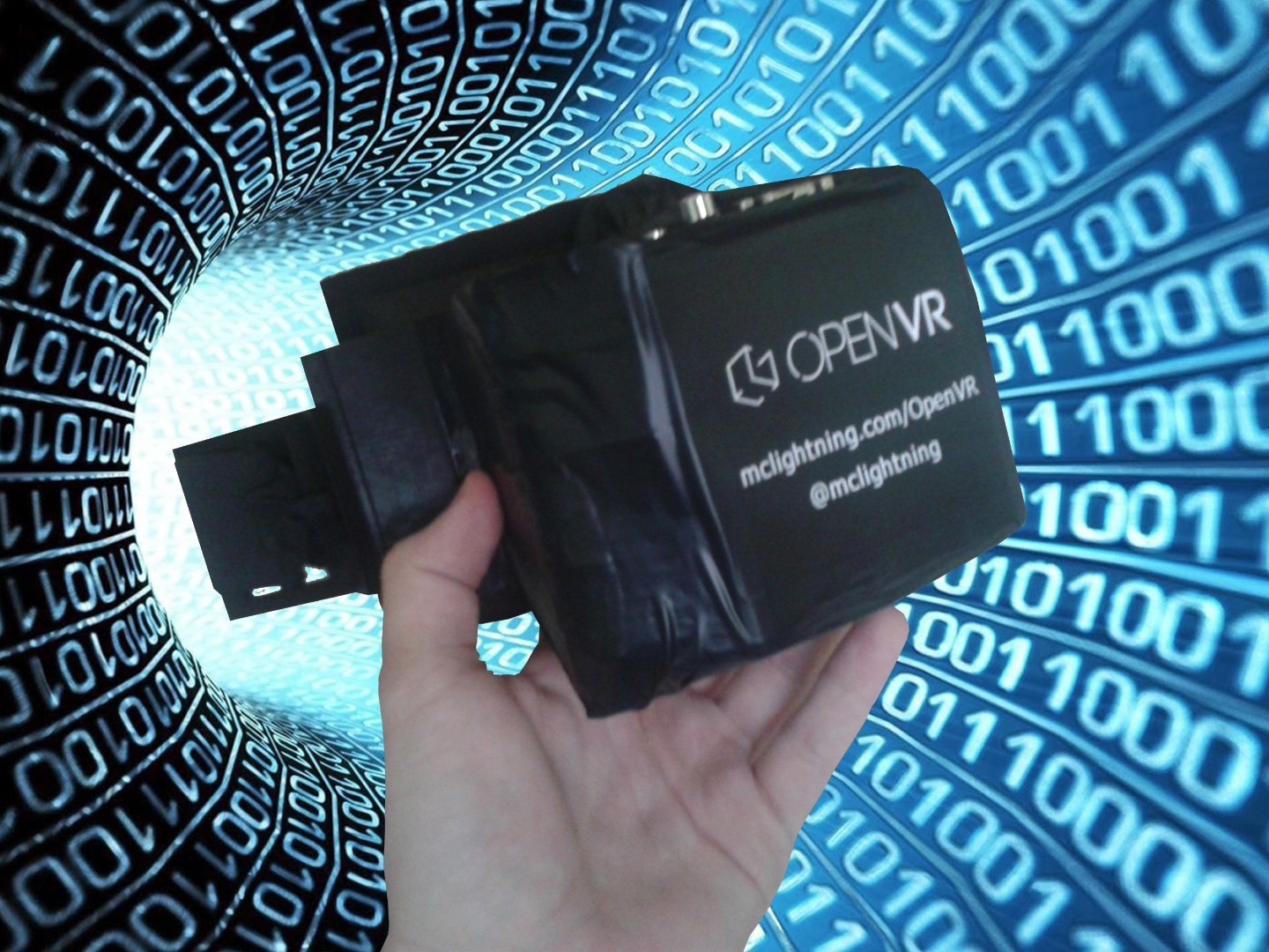
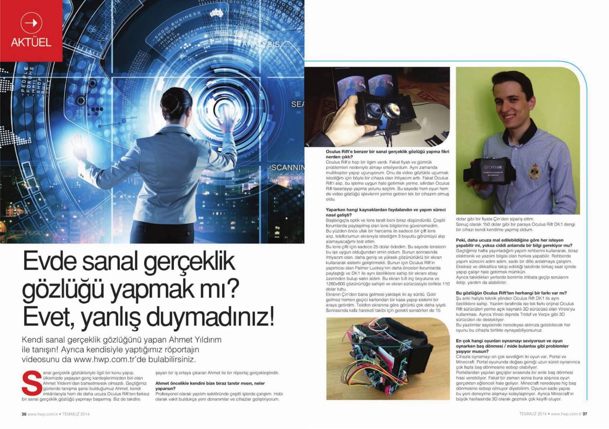
OpenVR is a virtual reality headset similar to Oculus Rift DK1. The best part is it cost around 150$ to build.
In this instructable, we will go through each step and you will have an home made Oculus Rift DK1 clone by the end.
Since it was opensource some people improved it further and made it work with Smartphones. That will be the topic of our next instructable.
This project was first published on June 2014. It gained a huge interest from maker communities all over the world and got great coverage on magazines. :
http://hackaday.com/2014/06/13/openvr-building-an-...
https://xakep.ru/2014/06/14/62636/
http://www.comptoir-hardware.com/actus/peripheriqu...
Materials
Before we begin building an OpenVR, let’s make a list of requirements.
Parts:
- Arduino Mini Pro
- GY-85 9DOF IMU
- USB to TTL Converter
- 5.6” 1280×800 LCD Display
- 12V Power Adapter for
- 2x (50mm 5x Aspheric Lenses)
- 3D Printed Case
- Shoulder Sponge Pad
- Some wires
Tools:
- Soldering Iron
- Hot Silicone Gun
- Arduino Software
- Processing Software
- Zip Package : https://github.com/ayildirim/OpenVR/archive/master...
Warning!
Don’t try lenses directly on your eyes in sunlight, intense room light.
I printed it using my delta 3d printer from GearBest.
If you also want to get a delta 3d printer, you can use special coupon code GBTE to get %12 discount on GearBest
http://www.gearbest.com/3d-printers-3d-printer-kit...
Hardware 1 : Headtracking Sensor
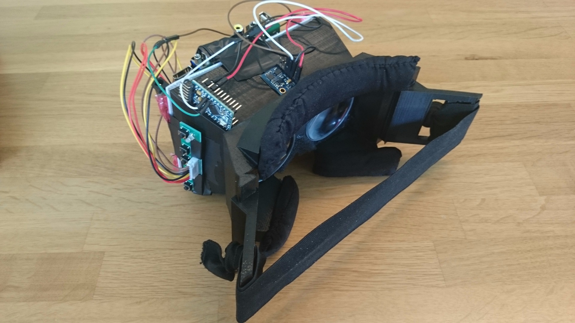
Pin connection
We will start with connection of Arduino and GY85 sensor module. Please carefully connect them according to connection table below.
GY85 - Arduino
- SDA - A5
- SDL - A4
- VCC - VCC
- GND - GND
Arduino Sketch
Please extract contents of zip archive.
- Open file /Arduino/Final_arduino_code.ino in Arduino Software
- Connect Arduino to PC using USB-TTL cable
- Upload sketch onto Arduino
Test
You will find a processing sketch in the zip contents. It will get data of headtracking sensor from Arduino. Then it will draw a visual representation of rotation.
Please run this file in Processing Software :
/IMU Calibration – Processing/Razor_AHRS_test/Razor_AHRS_test.pde
You can watch video of my test : https://www.youtube.com/watch?v=Gx6jRevFA4U
Hardware 2 : Assembly
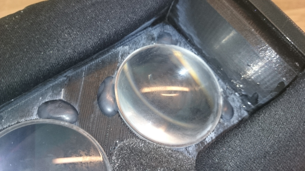
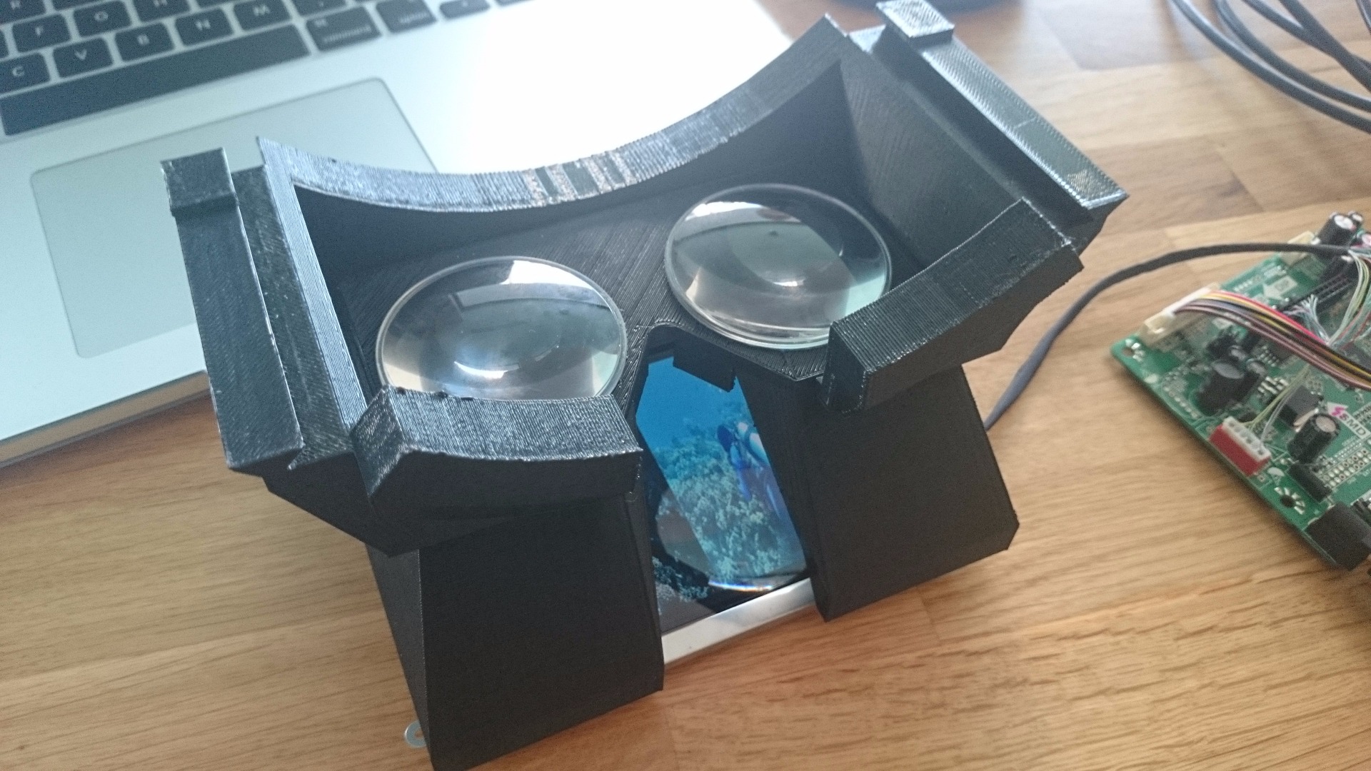
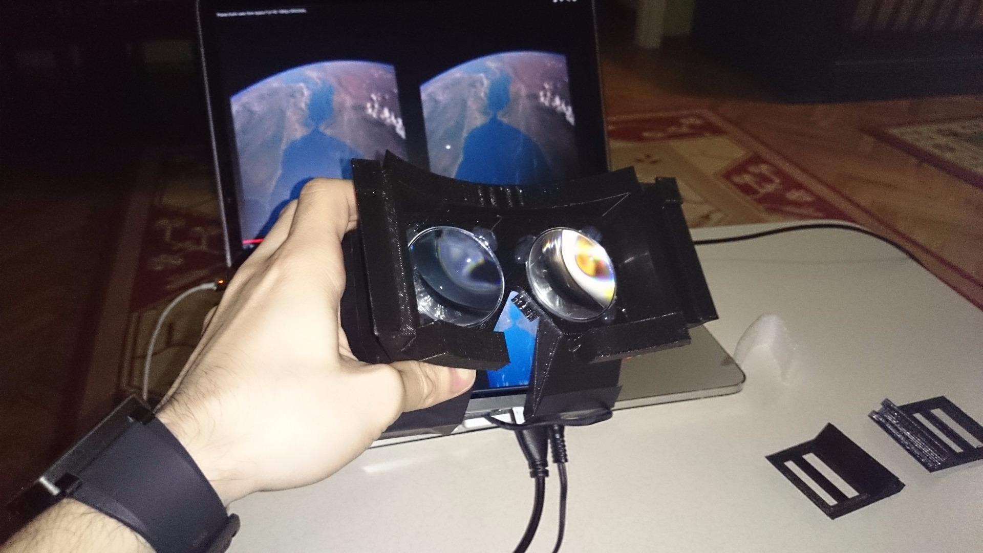
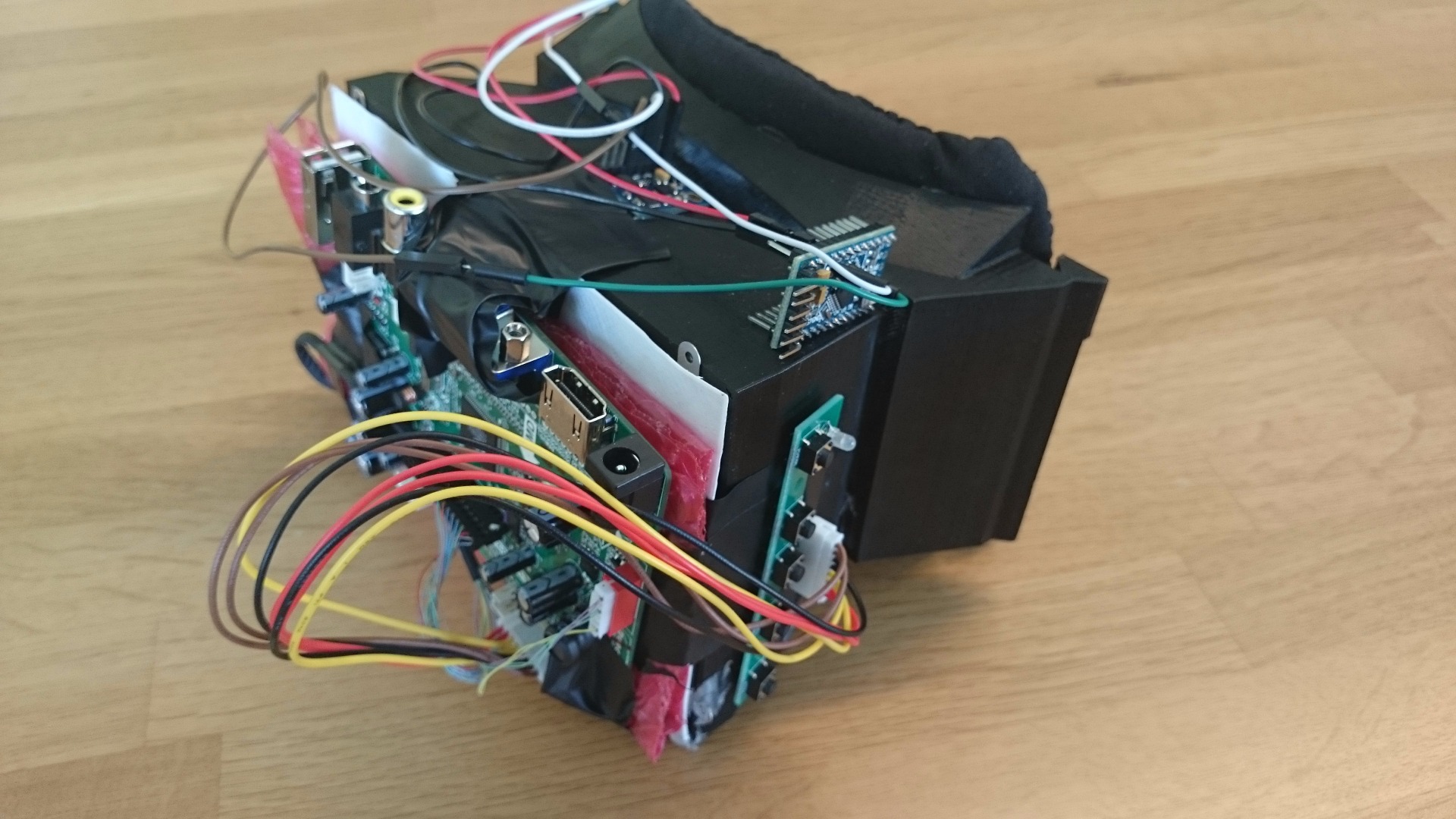
We can start assembling things together now. Then we will be done with hardware part of our project.
1. Lenses
The first and easiest is to place lenses. Gently place lenses onto holes on the 3D printed case. They should fit right into place since holes are specifically designed to hold the lenses.
Afterwards using hot silicone gun, glue lenses from their edges onto case carefully. Don’t pour too much silicone.
2. Display
We have the lenses on, but without a display, they are no good. Place the screen onto opening right in front of the lenses. I’m assuming you have the LVDS cable connected between the Screen and the Driver board.
Be very careful with the LVDS cable. They are pretty fragile and you wouldn’t want to wait for another shipment for weeks.
Glue the screen from screwing holes onto 3d printed case, using hot silicone gun.
Place the LCDPlace_1 onto back of the screen. This part will act as a separator between the screen and the driver board. Secure this part onto the screen using hot glue or tape.
I would suggest taping some bubble nylon onto this separator to increase heat insulation between driver board and screen. Because driver board gets very hot and you don’t want to damage the screen.
Then we need to place the driver board on the outside. Tape may not work for securing board because after several minutes of operation, heat from board loosens the tape. So you should probably use hot glue.
3. Test
Since we have both optics and display ready in place. We better test everything before taking further steps.
Now you should be able to watch a stereoscopic video using your OpenVR.
Connect driver board to your computer via HDMI, and connect power adapter to driver board. You may see a blue screen waiting for a video signal. You may need to set HDMI as input source using buttons of the driver board.
Display acts just like a monitor. You should set your computer to duplicate its display onto HDMI.
Afterwards search for a stereoscopic 3d video on youtube then play it on full-screen. You should be able to watch it using your OpenVR now.
4. Headtracking sensor
We are going to securely place both GY85 IMU and Arduino onto headset.
We will glue IMU onto headset like shown on the photo. We will pour some hot glue and then place and push IMU on it, before it cools.
Then we need to place Arduino onto headset. I would suggest gluing it sideways, because unused pins offers a surface for the glue. And it is easier to plug TTL side of USB to TTL converter, this way.
5. Sponge Pad for Nose and Cheek Rest
Carefully cut a linear piece from the sponge pad with a width of 1,5cm~.
Then stitch the cut opening of cloth back together.
Then glue it onto plastic surface that rests on your forehead.
Repeat these steps for each plastic piece that rests on your face by carefully cutting pieces from sponge pad.
Your OpenVR will be very comfortable to wear now.
Hardware 3 : Optional Sensor Calibration
If you would like to make headtracking sensor work more precisely, you can do sensor calibration.
You can learn about this on following page:
https://github.com/ptrbrtz/razor-9dof-ahrs/wiki/Tu...
Software 1 : Head Tracking Injection Into Games
PC games use several different protocols to accept head tracking input, such as; TrackIR, FreeTrack etc.
We will use FreePie application which is able to send our sensor data in different protocols.
1. Please download and install FreePie;
http://andersmalmgren.github.io/FreePIE/
2. Connect Arduino to PC with USB-TTL cable
3. FreePie
We have several scripts ready in the contents of zip archive. We will use one for Vireio Shared Memory Tracker.
Please open file on FreePie: /FreePie/FREEPIE vireio GY85.py
Run the script, you should first see 3 zeros for a few seconds. Then FreePie will start fetching sensor data from Arduino and it will show 3 axis rotation values in console instead of those 3 zeros.
When we finally setup 3D SBS, you will leave it running in background like this. This will inject head tracking into the game.
Software 2 : Vireio 3D Side by Side Rendering
Vireio is an opensource project that converts your regular PC games to 3D SBS. So you can play them in OpenVR or Oculus Rift.
Community of Vireio works actively on improving it. So please visit their page for updated instructions on installing Vireio:
http://www.mtbs3d.com/index.php?option=com_content...
When you run Vireio after installation is done, please select “DIY Rift” and “Shared Memory Tracker”, instead of those selected in the guide. Because it is usually written for Oculus Rift.
If it is still not working and you’re seeing same old 2d game. Try copying d3dx9.dll from Vireio folder to nearby executable file of the game.
Make sure to have FreePie up and running before starting game, so you will have headtracking.
Software 3 : Commercial Alternatives for 3D SBS Rendering
There are a few other alternatives to Vireio. These are paid and not covered in this guide.
If you are not happy with Vireio, you can try this paid alternatives.
Here is my comparison among all these options:
- Vireio : Free Open-Source, Easier Head-tracking Setup, Good Community Support
- Tridef : Paid, Trial Option, Multimedia Support, Easy to setup
- Vorpx : Paid, No Trial Demo
Result
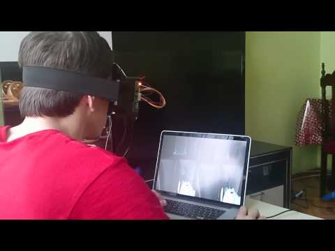

Please vote for me in 3D printing contest. So I can make a better version that also supports Smartphones.