Open Access and Open Source Motorized Telescope Mount
by jacksonshell07 in Workshop > 3D Printing
1747 Views, 25 Favorites, 0 Comments
Open Access and Open Source Motorized Telescope Mount
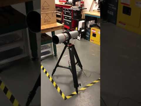
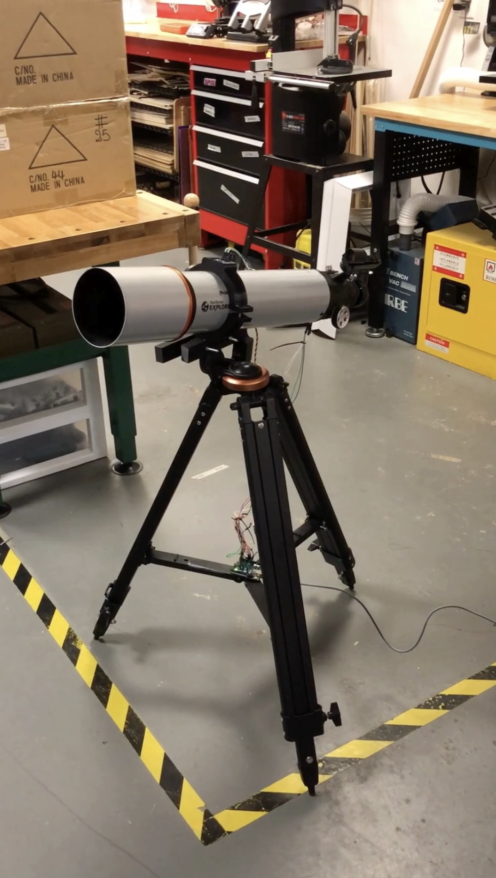
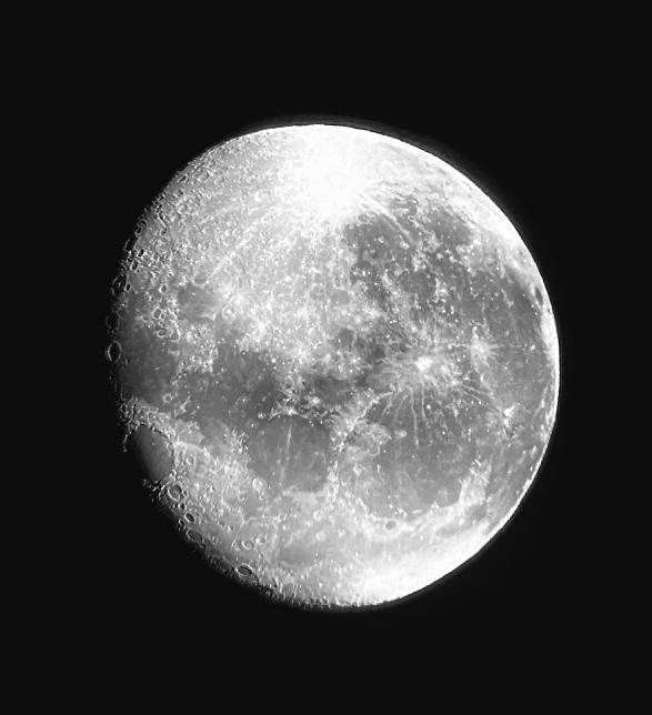
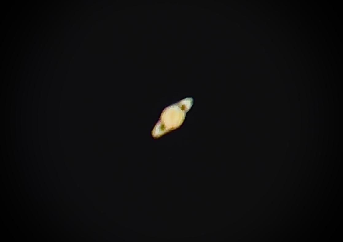

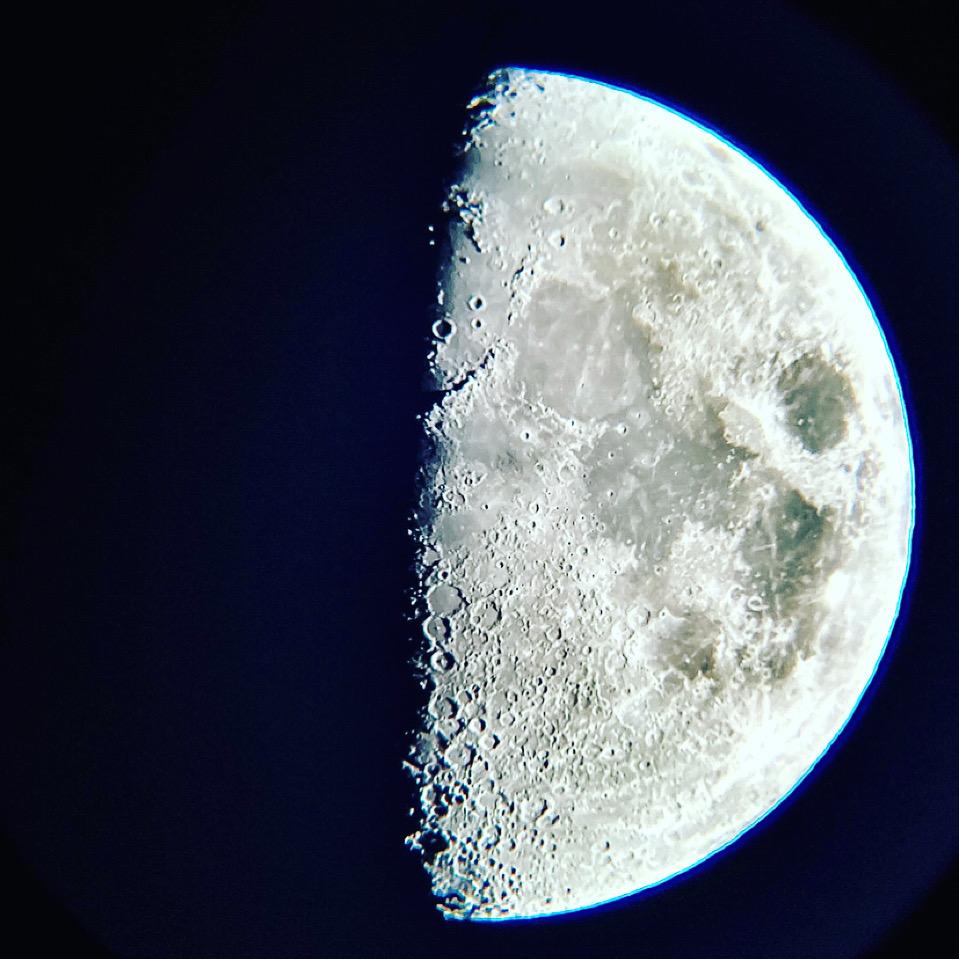
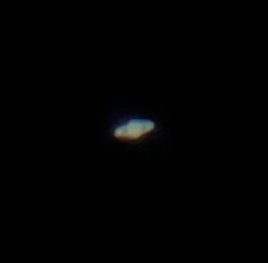
I’ve always wanted a motorized telescope mount but could never justify the steep cost. So, I decided to combine my passion for astronomy and innovation to create something more accessible, and I’m excited to share it with you. This project transforms a regular manual altazimuth mount into an automated system that can adjust both altitude and azimuth to point at stars, planets, and other celestial objects. Instead of making manual adjustments, you simply set the coordinates, and the telescope moves on its own!!
(The above photos were all taken by my telescope!!!)
If you run into issues there is a Troubleshooting section at the bottom
Supplies
Electronics:
- Arduino Uno R3
- Adafruit BNO055 Absolute Orientation Sensor
- HS-788HB Servo
- HS-311 Servo
- Jumper wires
- Arduino Uno R3 USB Cable
Physical Components:
- StarSense Explorer DX 102AZ
- Filament
- 4x M6 Screws
- 6x M6 Nut
- 2x Servo Hat Screw (comes in the HS-311 Servo box)
- 4x zipties
- velcro sticker
Software and Tools:
Taking Off the Telescope From the Mount
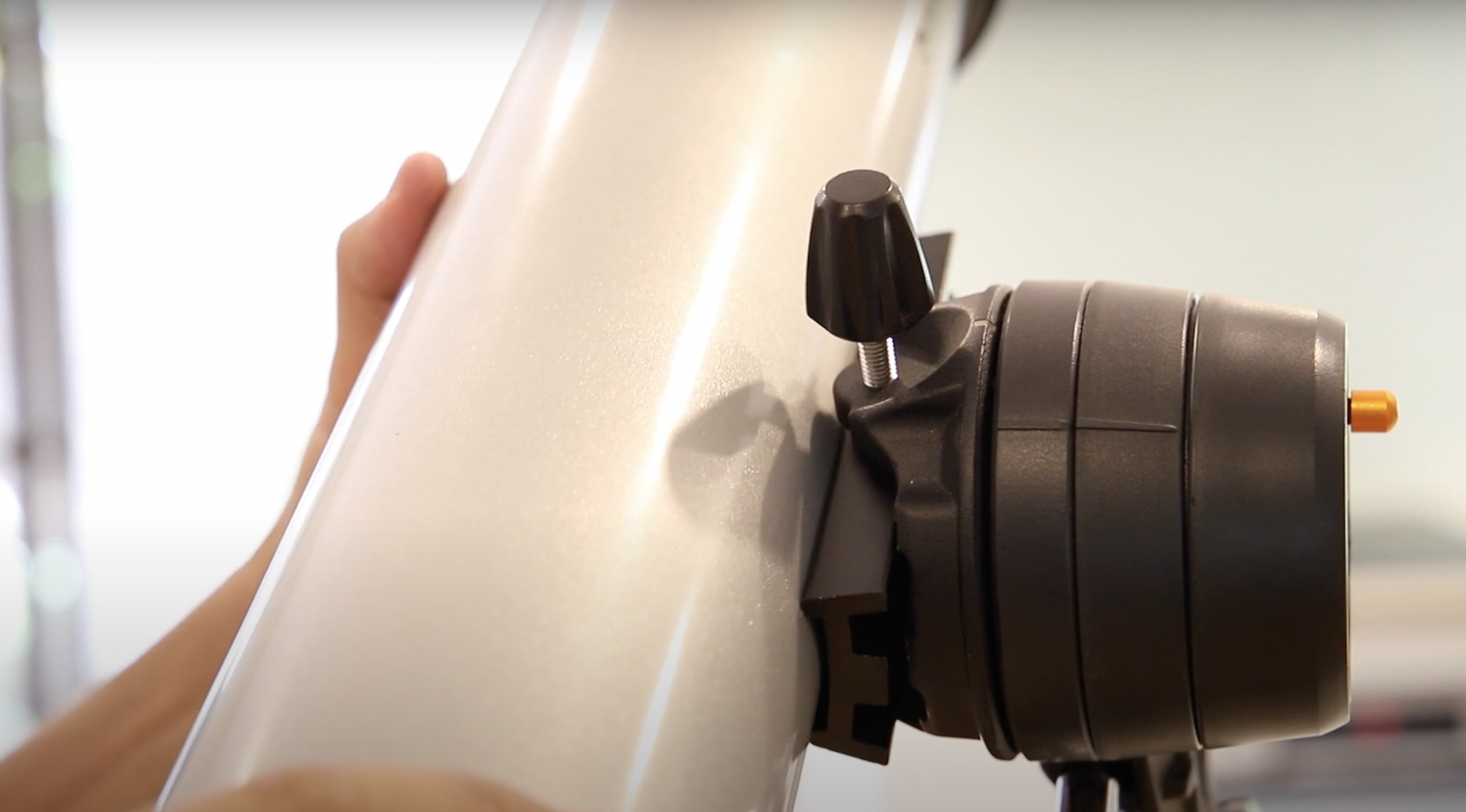
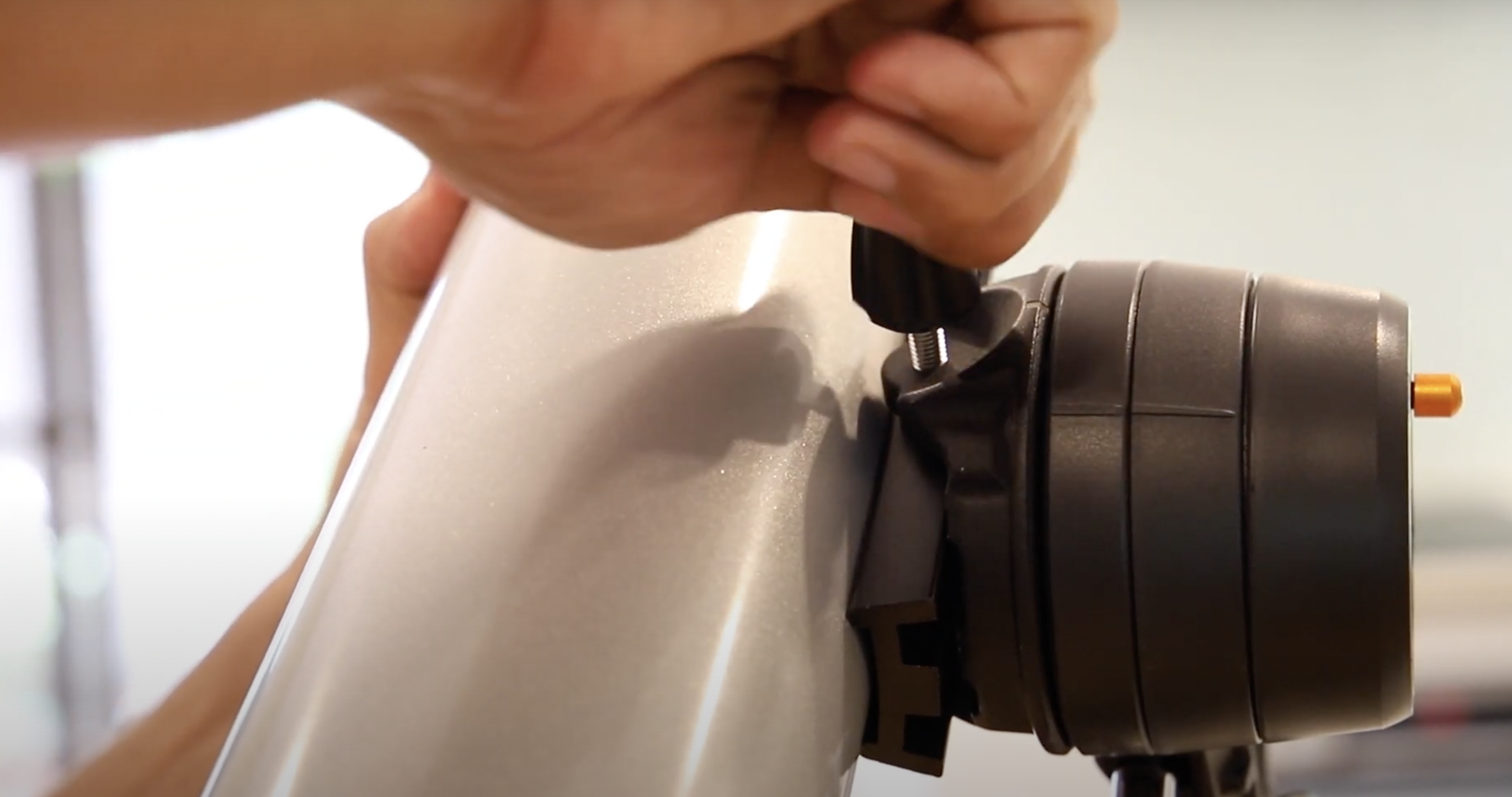
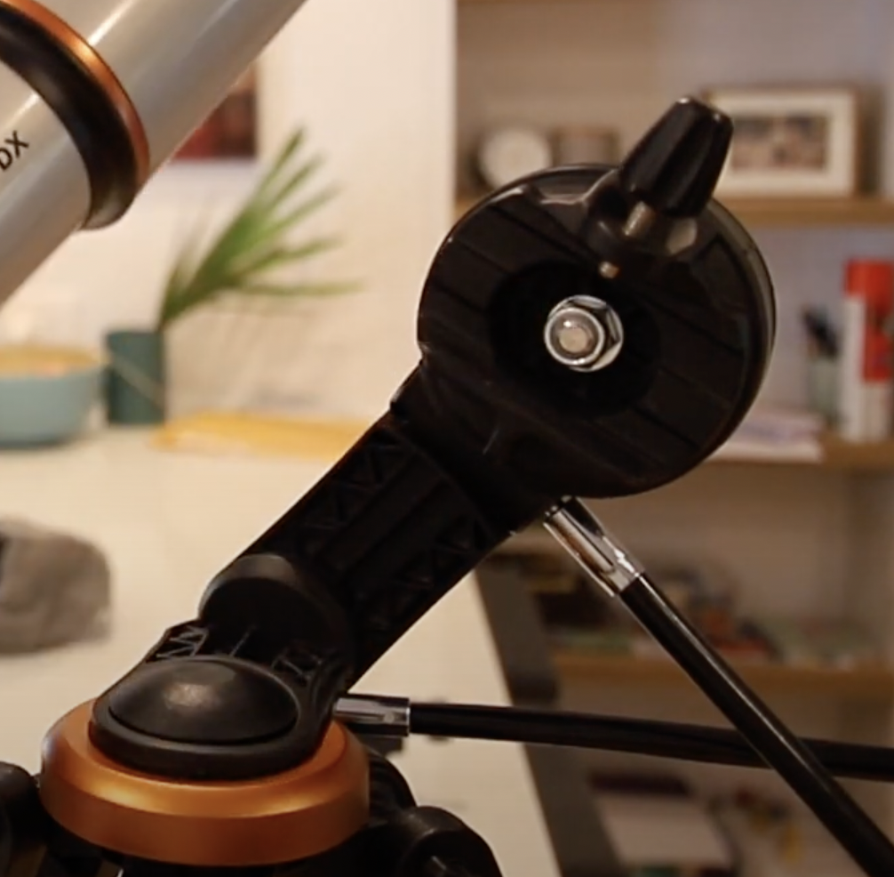
Once you gather your materials you will need to remove the telescope from the mount. Please refer to the quick setup manual to correctly deconstruct the telescope.
image source: Celestron
Removing the Slow-motion Controls
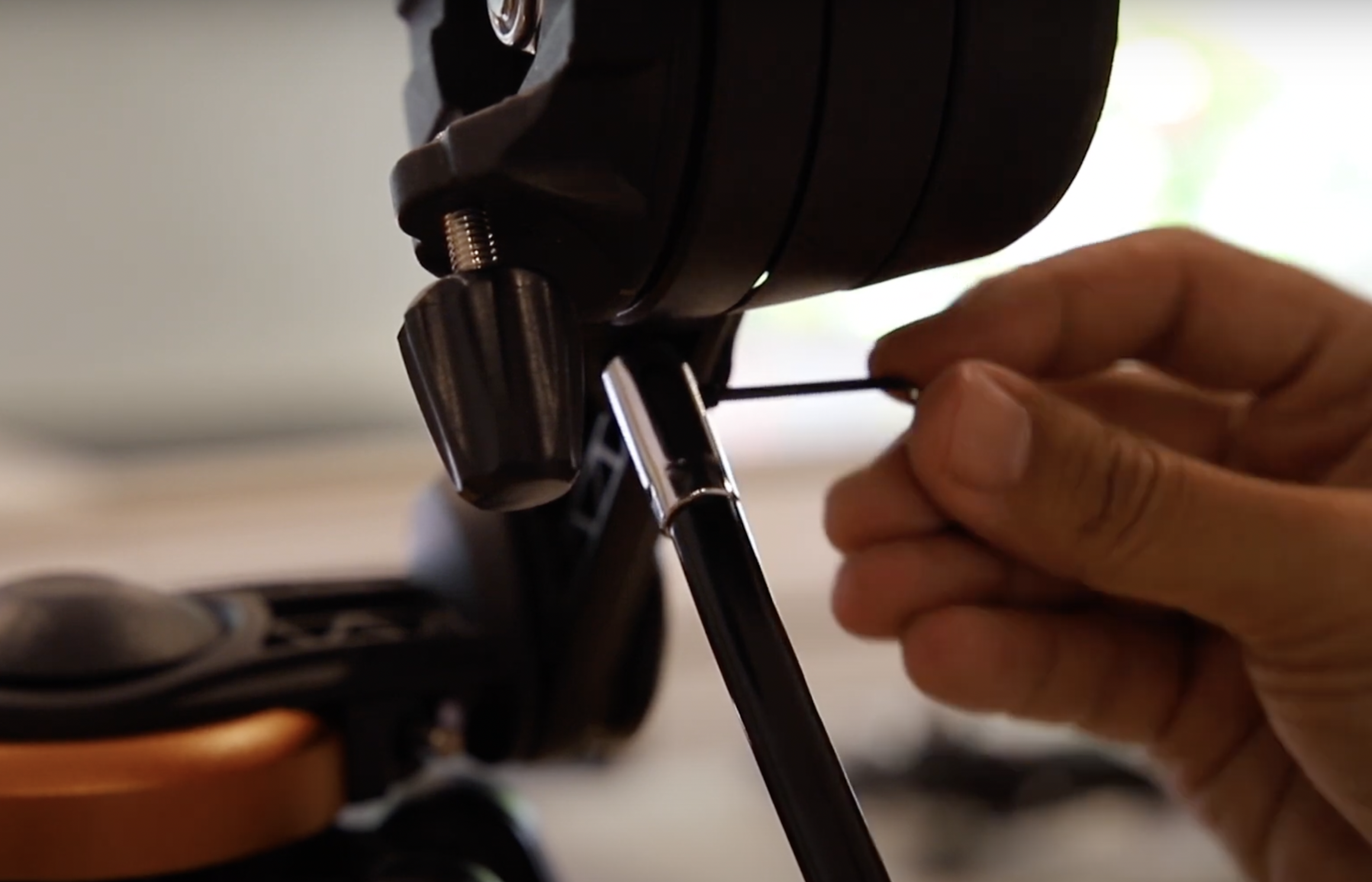
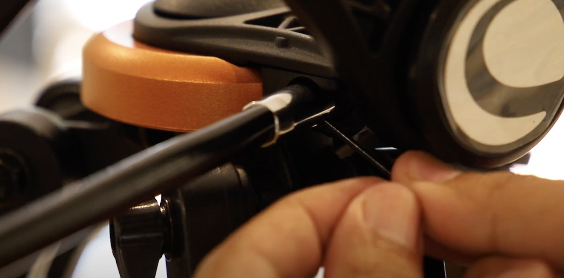
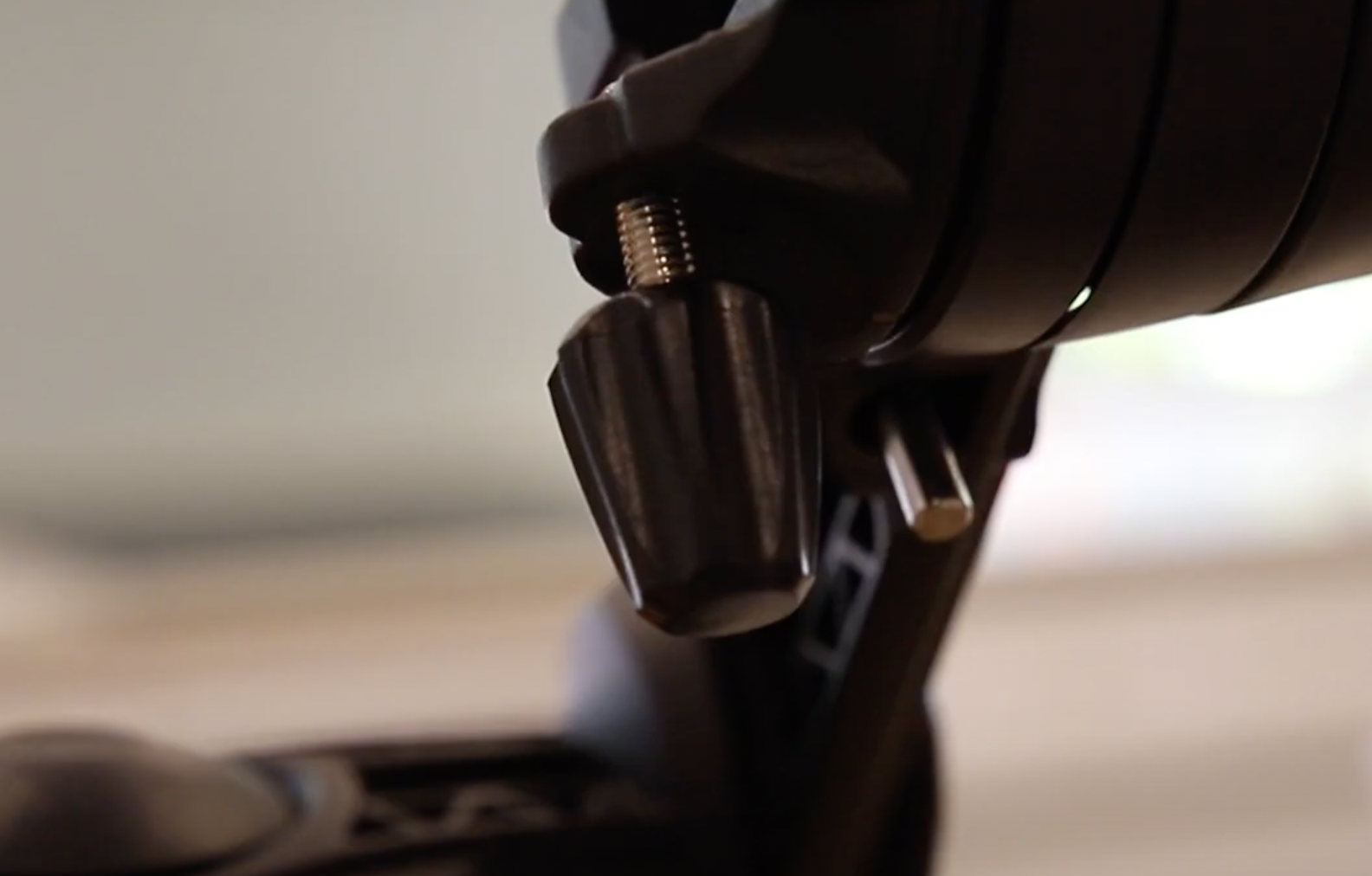
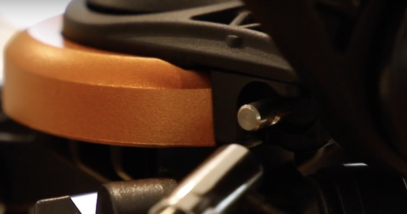
After the telescope is removed unscrew and take off the slow-motion controls attached to the mount. Please refer to the quick setup manual to correctly deconstruct the telescope.
Image source: Celestron
3D Print Motor Mounts and Sensor Clamp
After removing the slow-motion controls and detaching the telescope from the mount, you can print the motor mounts, servo connector, and ring clamp for the sensor.
I designed these parts in Fusion 360 (see files below), testing different configurations to ensure the motors fit properly without interfering with the telescope's movement. The ring clamp is tailored for a 102mm telescope and is compatible with the BNO055 sensor.
Printing Recommendations:
Infill: 20%
Resolution: 0.15mm
Supports: Tree supports
Once the parts are printed, clean off any supports and glue (if used). The motors should fit snugly into the mounts with minimal movement, and the ring clamp should fit securely around the telescope. Use screws to fully attach the ring clamp to the telescope. If you run into issues there is a Troubleshooting section at the bottom
While your parts are printing, move on to Step 4!
Downloads
Making the Servos Continuous Rotation
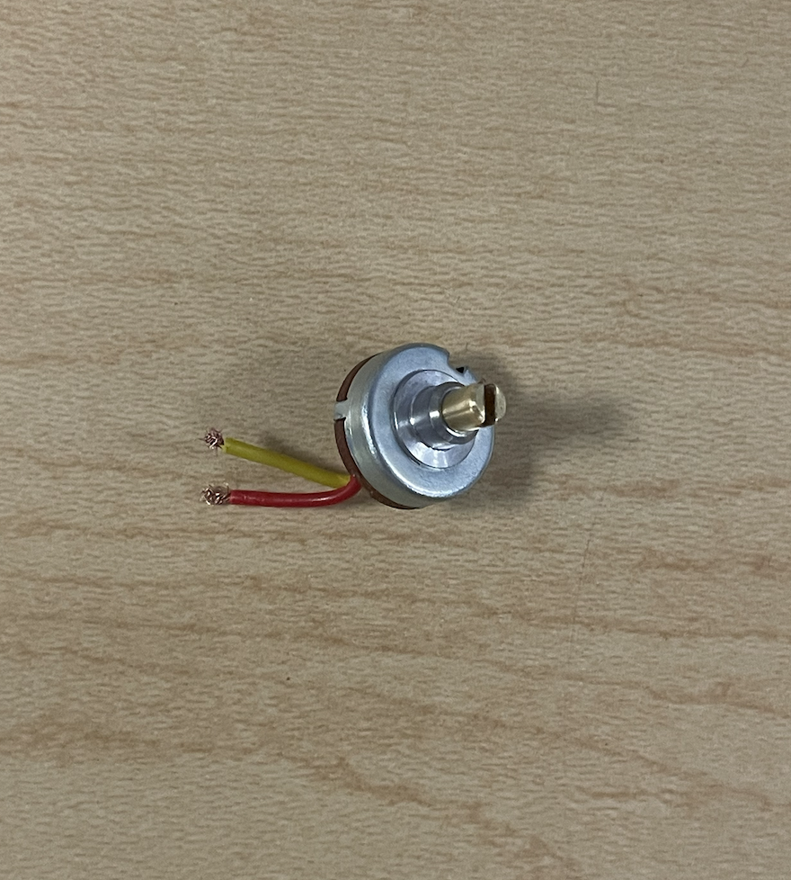
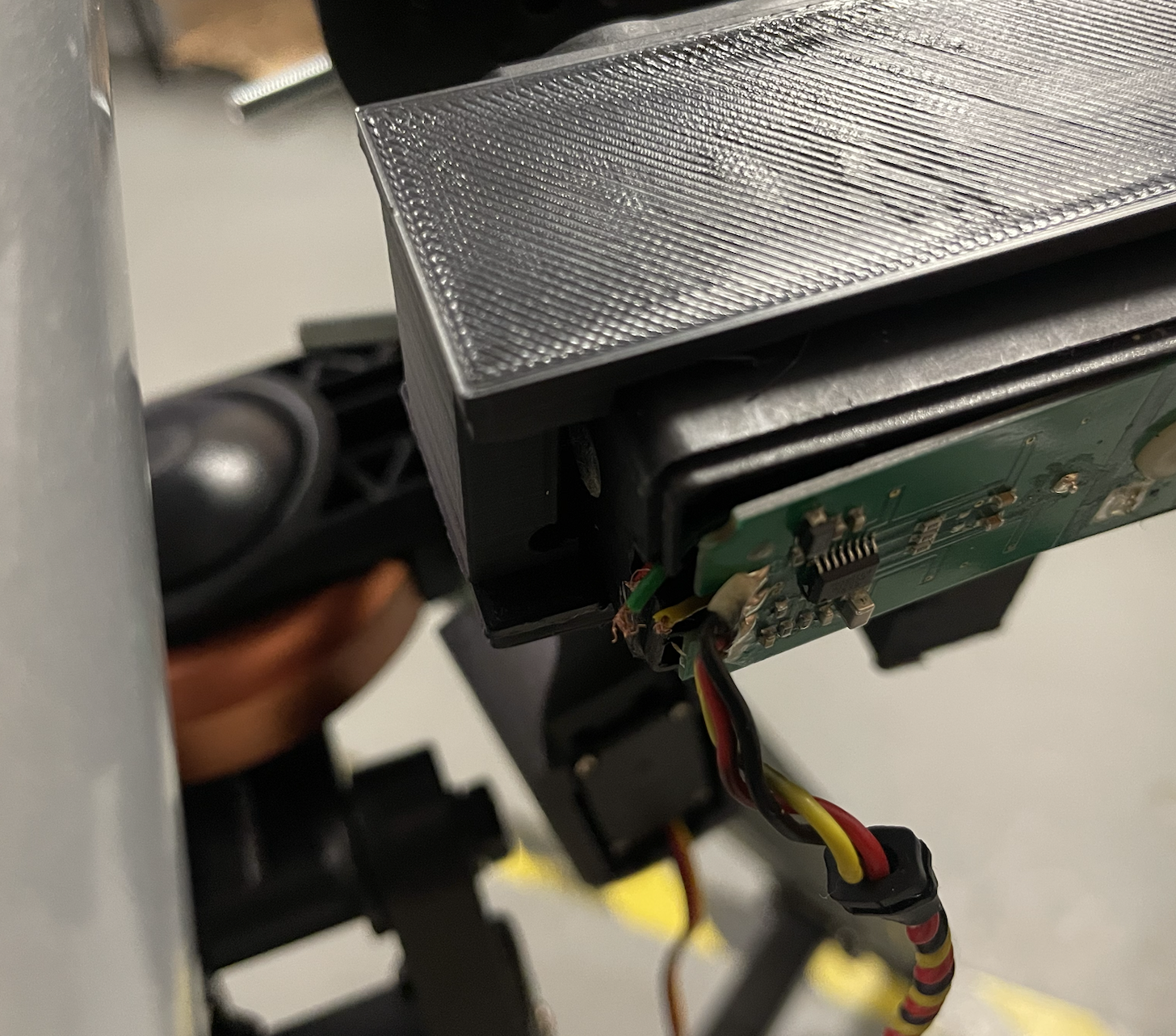
For this project, we have two different types of servos; however, neither of them is a continuous rotation servo.
Let's start with the HS-311. For this step, you should follow this tutorial by Chris Wilkinson, it is very helpful and easy to follow.
The HS-788HB servo is a bit more challenging to modify. Here’s how to do it:
1. First, unscrew the back cover (just as you did with the HS-311 servo).
2. You will not be able to remove the circuit board from the servo, so DO NOT attempt to take it out! You will only need to slightly bend it open to access the wiring inside.
3. Once you can see inside, take a small screwdriver or any item that can fit inside and carefully scoop out the three wires. They should be red, green, and yellow.
4. After you have scooped the wires, gently pull them out. If done correctly, the potentiometer should come off.
5. After completing these steps, your servo should now function as a continuous rotation servo. For easy access, I did not screw the back cover back on, but it’s okay to do so if you did.
Servo Connectors
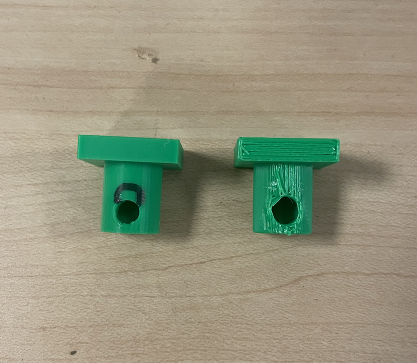
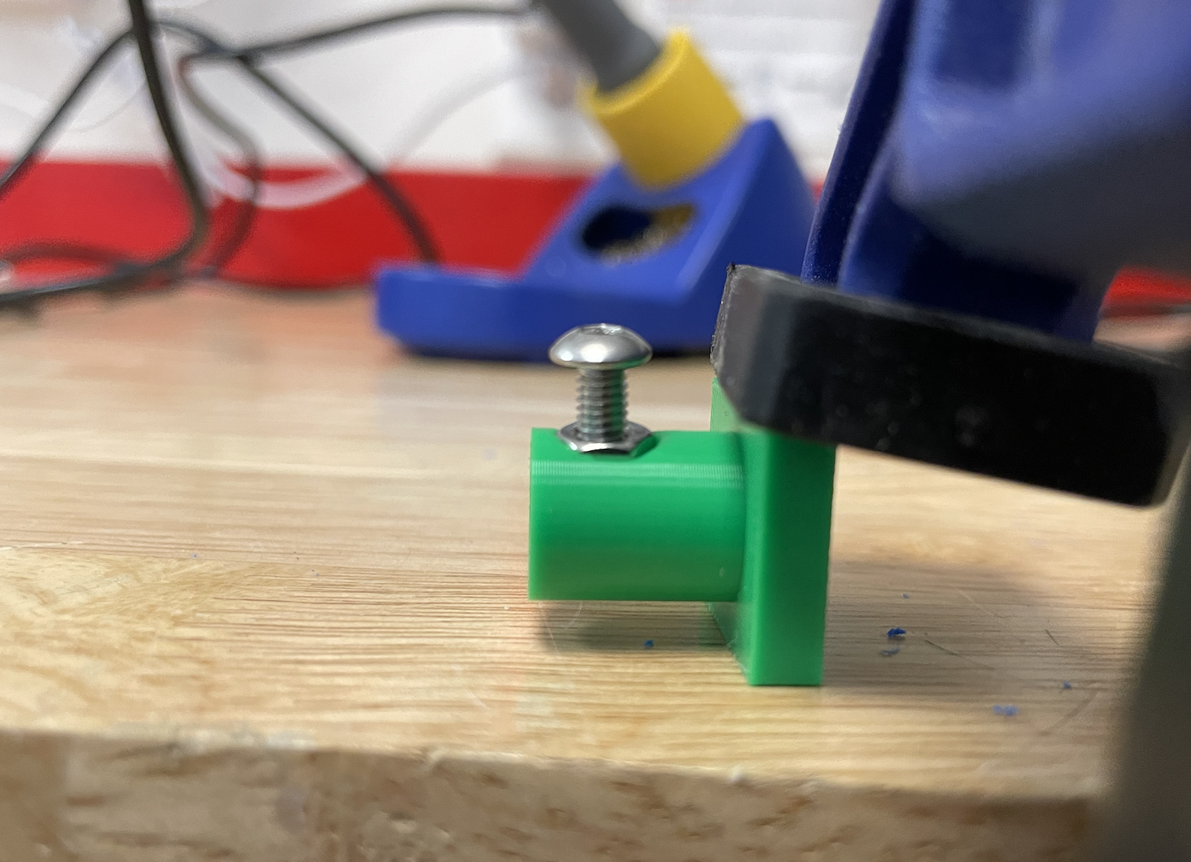
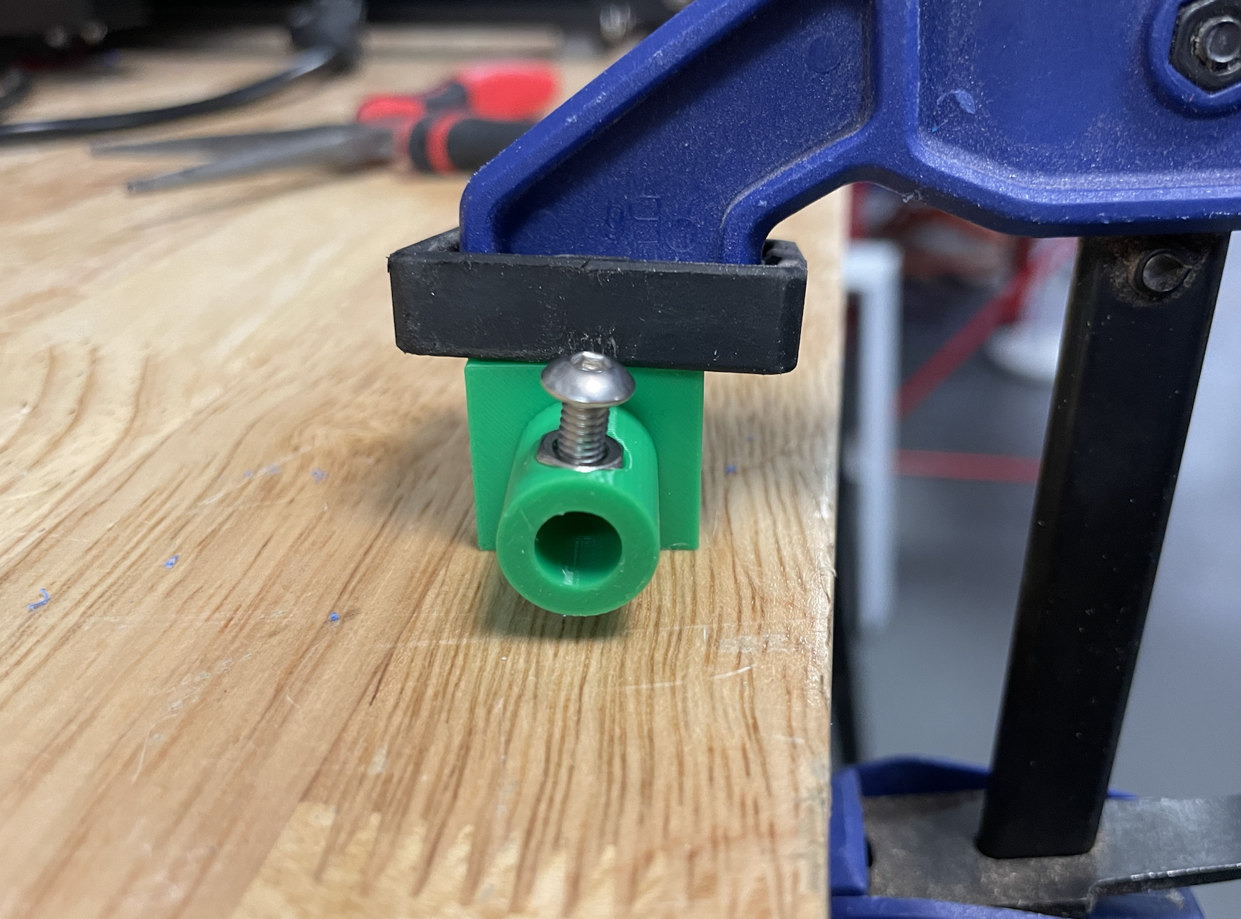
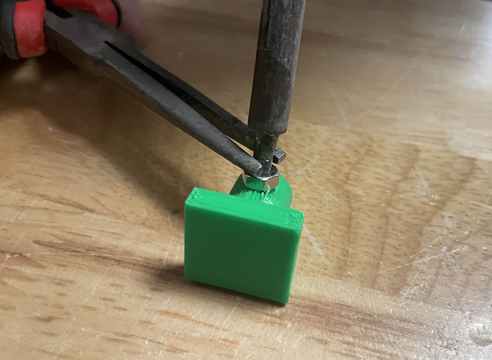
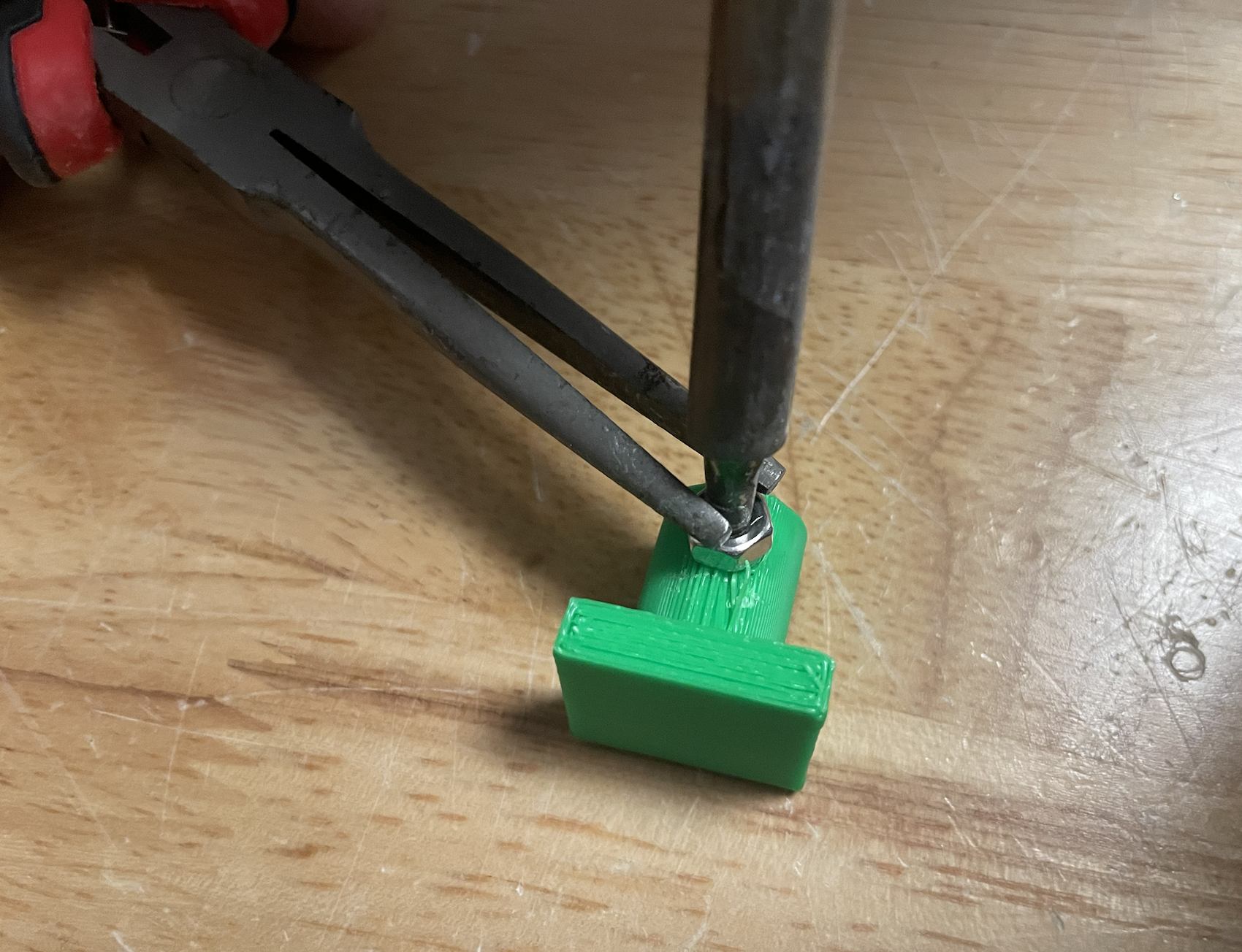
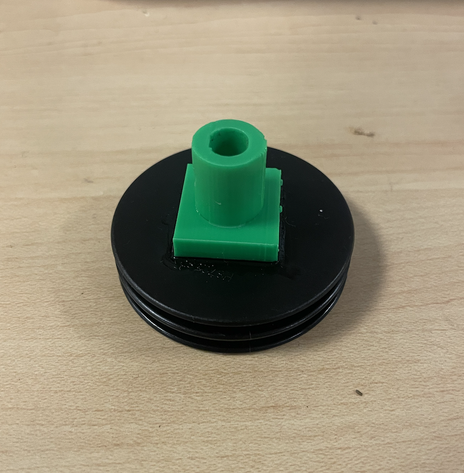
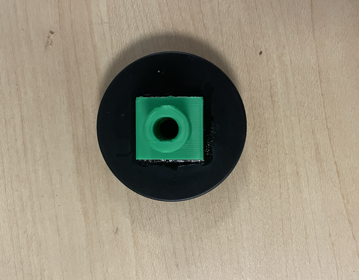
After 3D printing, you should have two rotary knobs. These will be used to connect the servo to the metal knobs on the telescope that control the gears.
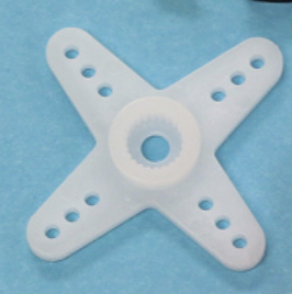
Then use a soldering iron to heat the M6 nut, then use pliers to push it down into the knob, allowing the nut to sink in completely. If done correctly, you should be able to screw in an M4 screw that is 8mm long. For the HS-788HB servo, I needed to glue a spool onto the knob to ensure a proper fit. For the HS-311HB servo, I needed to screw in a servo hat into the knob to connect the servo to the knob.
After setting up the servo knobs, screw the knob into where you removed the slow-motion controls.
Attaching the Servo Mounts
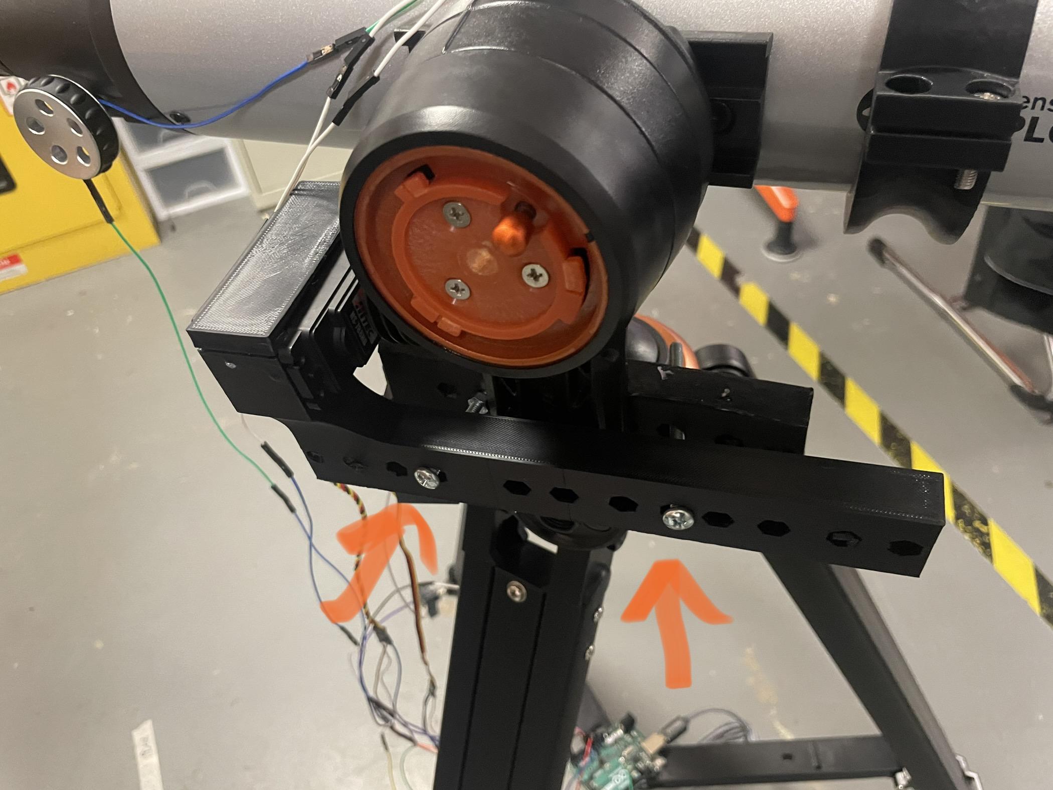
Slide the servos into their respective mounts (HS- and secure them using M6 bolts that are 60mm long along with M6 nuts, as shown in the photo. However, you can use any screw size you prefer; I just opted for these.
Ring Clamp and Bno055
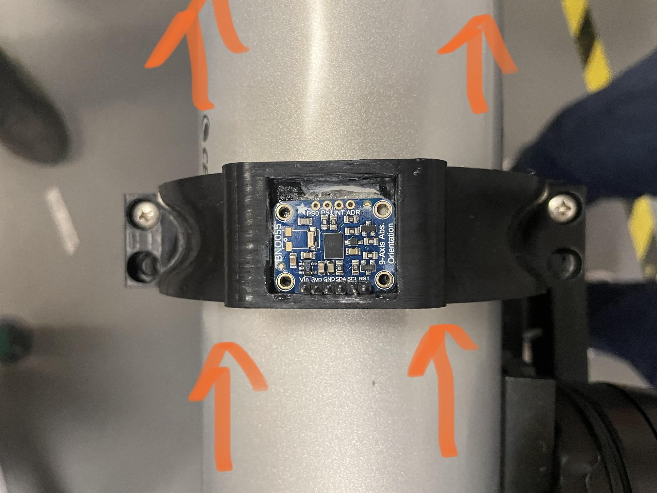
Once your servos and their mounts are set up and attached, we can proceed to set up the ring clamp and the BNO055 sensor.
1. Place the top clamp with the sensor area facing upwards.
2. Insert and align the BNO055 sensor into the holding area on the top clamp. Adjust its placement to match the reference image, ensuring the arrows point toward the end of the telescope, indicating the direction of view.
3. Use an adhesive (I recommend Krazy Glue) to secure the sensor in place.
4. Once the adhesive has dried, attach the ring clamp with the top clamp on top of the telescope using M6 screws. These screws worked well for me, but any suitable screws should be fine.
Wiring
.png)
.png)
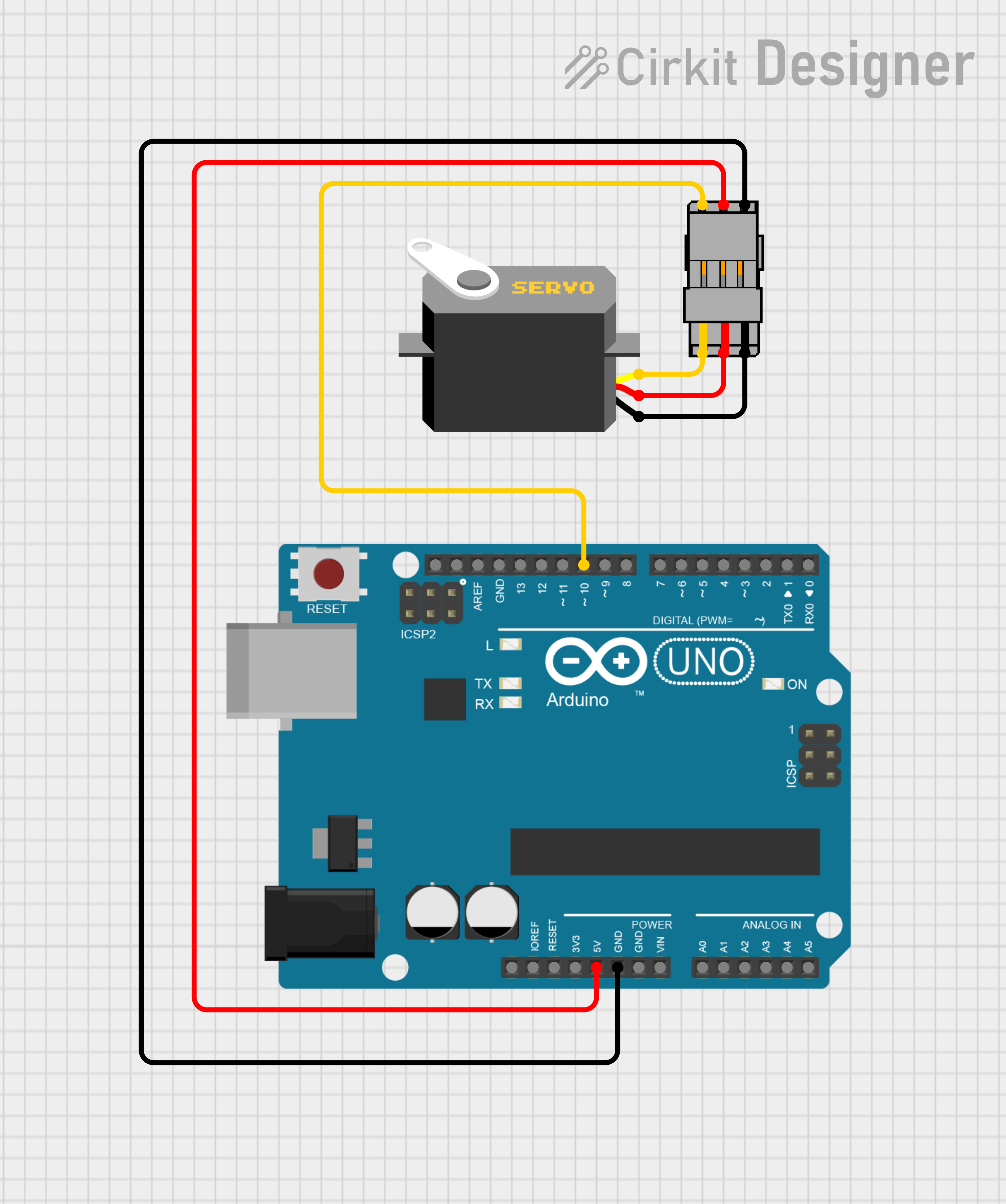
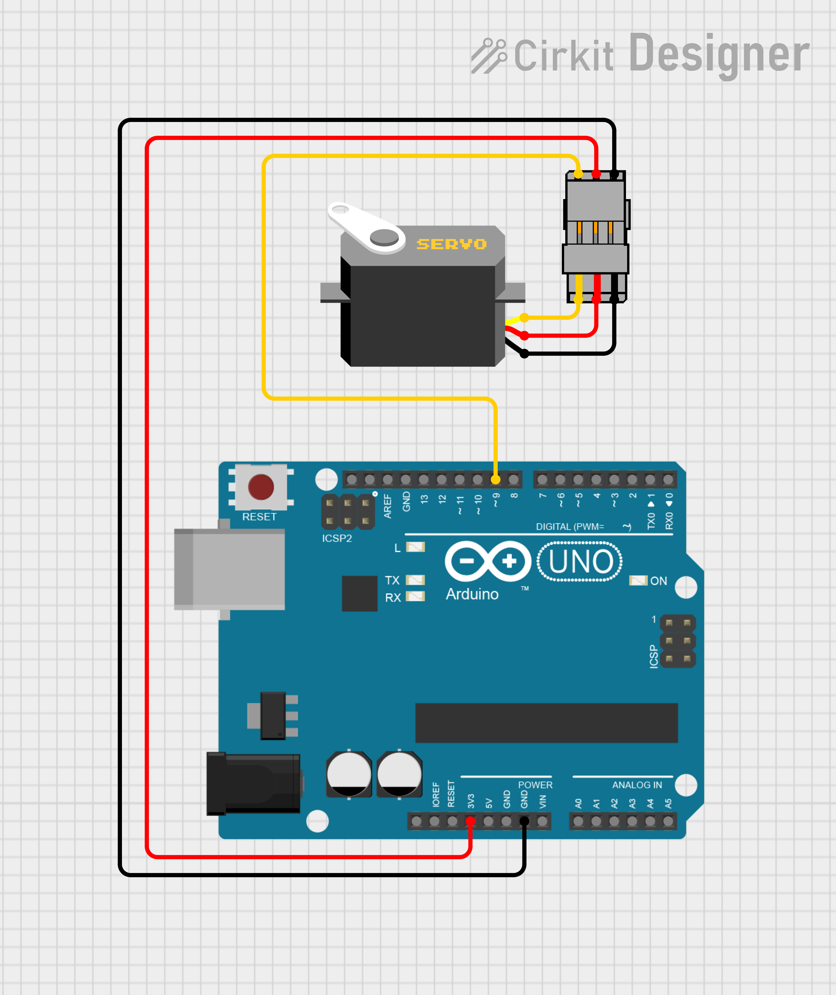
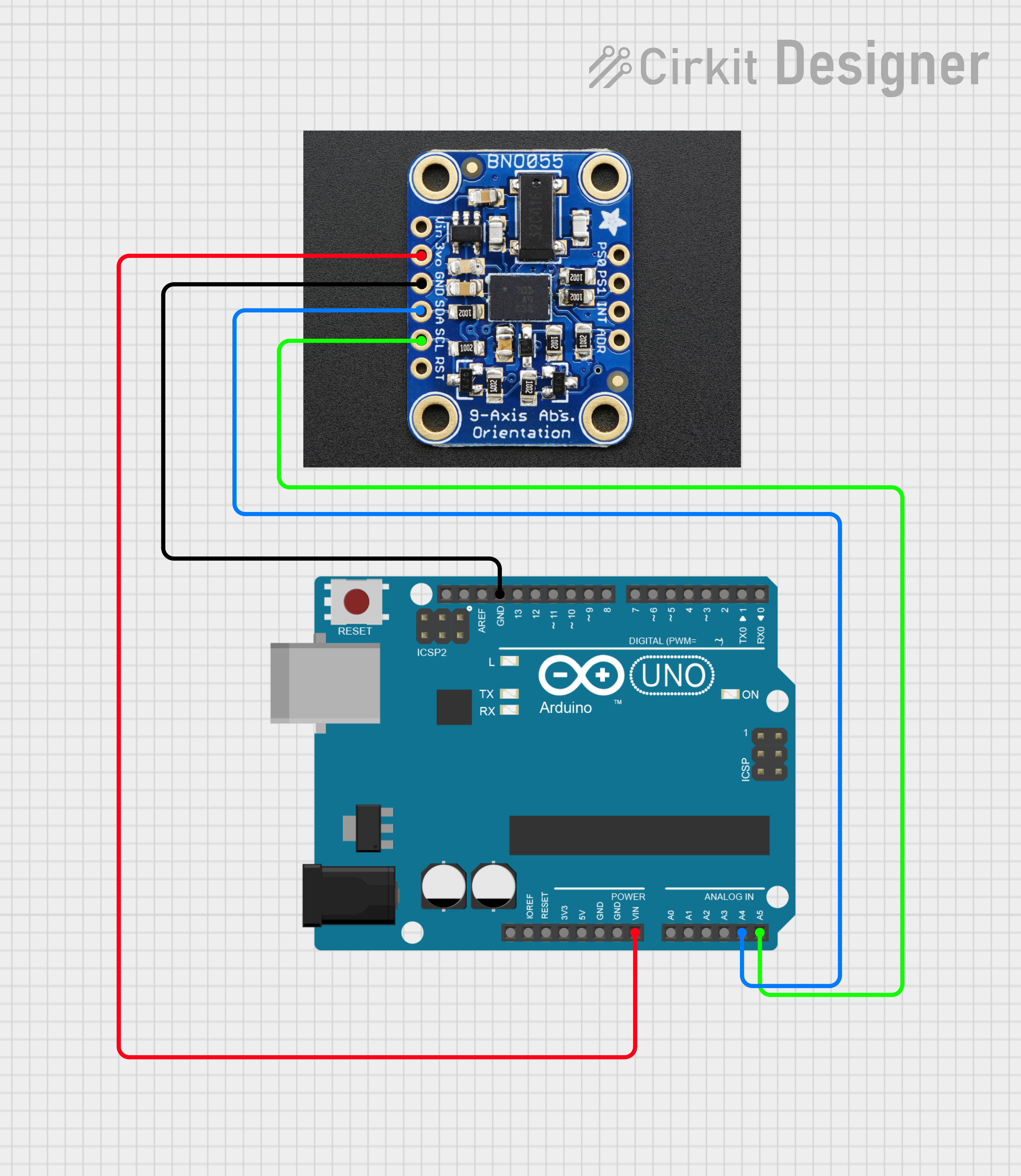
above are images of the wiring made on CirKit Designer you can use them to help you connect the Arduino to you servos and sensor.
Wiring the BNO055 Sensor:
- BNO055 to Arduino:
- VCC (BNO055) → Vin (Arduino)
- GND (BNO055) → GND (Arduino)
- SDA (BNO055) → A4 (Arduino Uno) or SDA (for other boards)
- SCL (BNO055) → A5 (Arduino Uno) or SCL (for other boards)
Wiring the Servos (Heading and Altitude):
The servo objects control two different servos: one for heading (bottom) and one for altitude/elevation (top). Connect them to specific pins on the Arduino.
- Servo for Heading:
- Signal Pin (Heading Servo) → Pin 9 (Arduino)
- VCC (Heading Servo) → 5V (Arduino)
- GND (Heading Servo) → GND (Arduino)
- Servo for Altitude:
- Signal Pin (Altitude Servo) → Pin 10 (Arduino)
- VCC (Altitude Servo) → 5V (Arduino)
- GND (Altitude Servo) → GND (Arduino)
Organizational Tip:
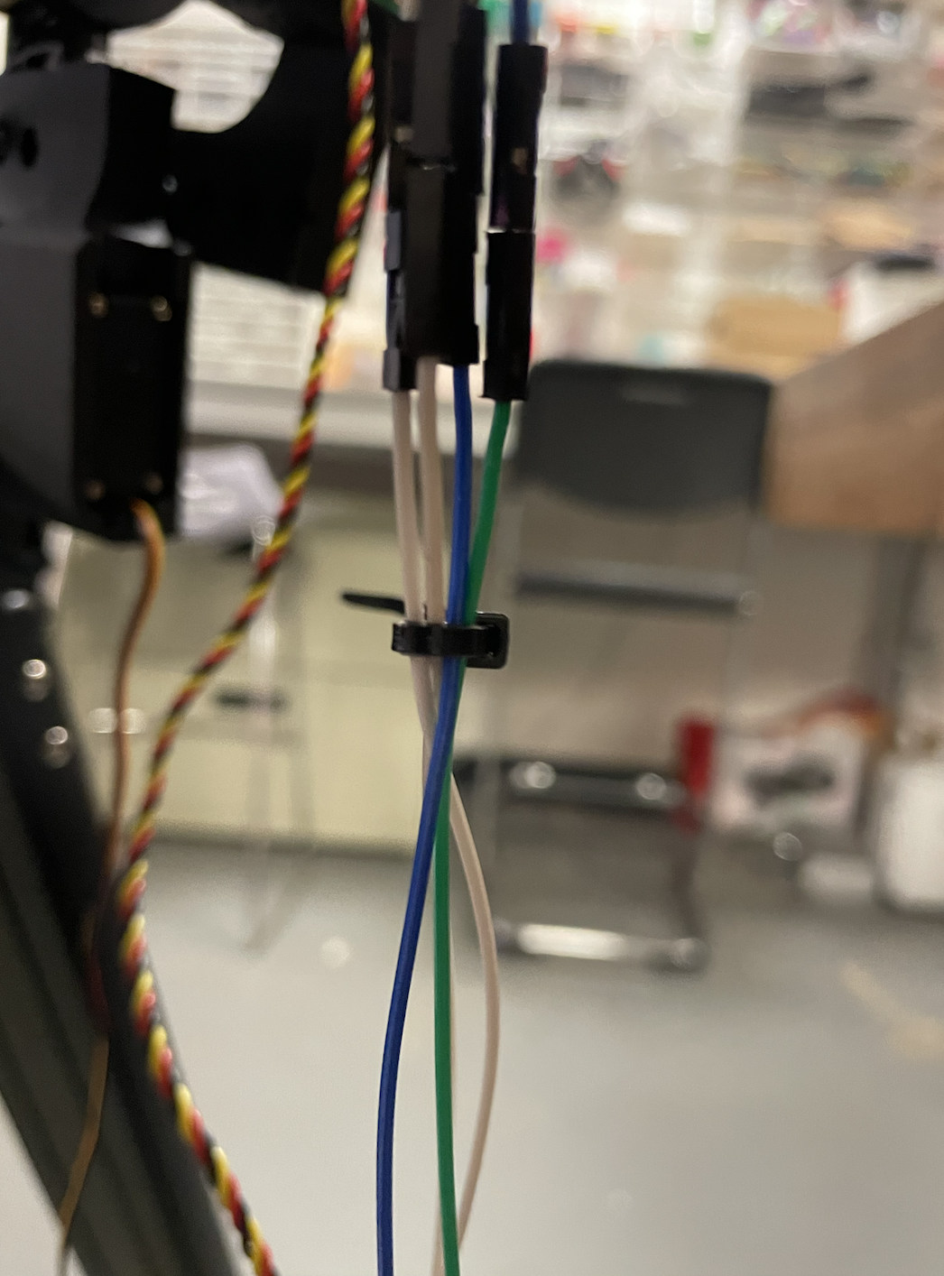
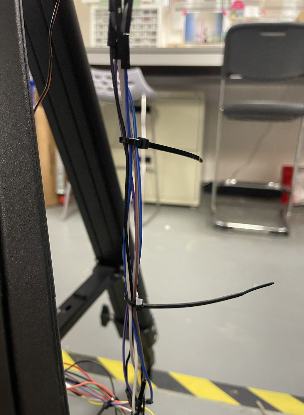
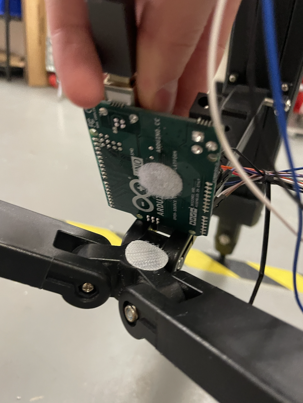
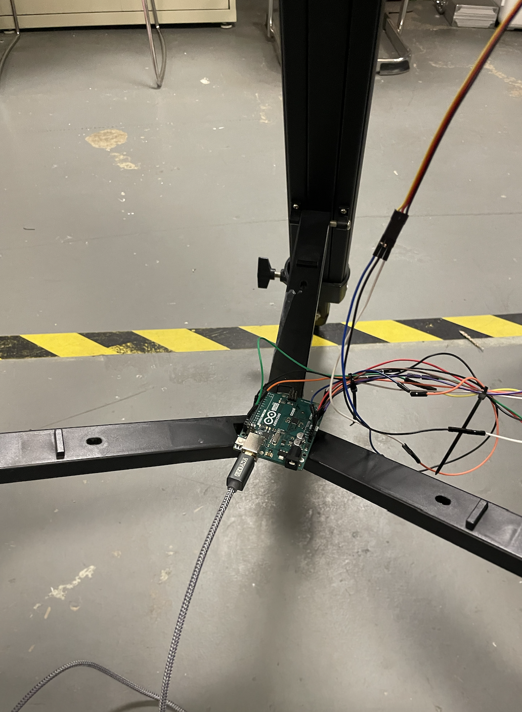
For a more organized setup, use zip ties to bundle the wires together. Additionally, place the Arduino on the middle support bridge of the telescope mount, attaching velcro stickers to the underside of the Arduino and the center of the support bridge. You can see images of my use of zip ties and velcro stickers in the images above.
CODE
Follow the pseudo-code steps in my code to understand why I made certain decisions but it should be plug and play:
How to Modify and Run the Code
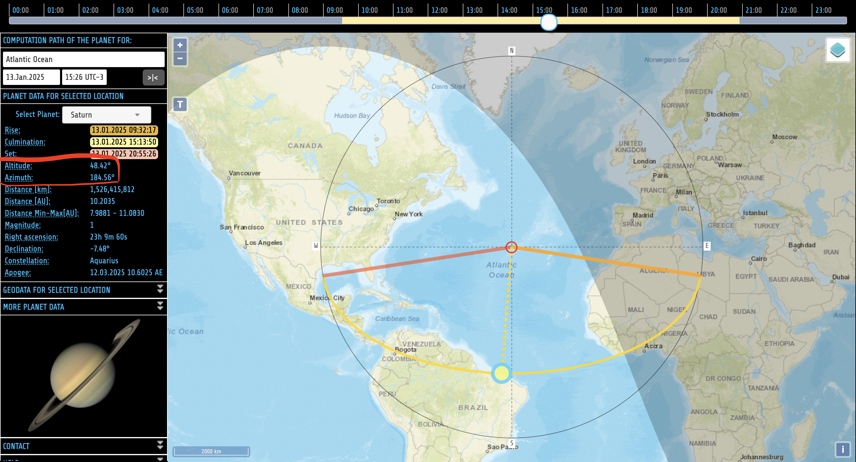
To use the code you must first set up the telescope so that its heading is True North and set its altitude angle to 0º. You will also need to know the azimuth and altitude coordinates for an object you want to look at. These values change depending on your location and the time of day.
You can easily find this information using the website TheSkyLive or Planets Calc (I recommend Planets Calc) which provides real-time data on visible celestial objects. Above is a screenshot of the Planets Calc website. You can find the azimuth and altitude coordinates on the left-hand side.
Then once you have the two values enter them into the code
Example:
- If the object you want to track has an azimuth of 150° and an altitude of 45°, set the following values in the code:
Fine-tuning: If the telescope doesn't point exactly where you expect, you may need to adjust the target values or recalibrate the sensor. This can happen due to minor errors in the sensor alignment or mechanical setup.
YOUR GOOD TO GO!!!
once you're done with all of these steps go test it.
If you want to learn more about the topics in this project I have put a few links below that I found very useful and worth my time:
Long Exposure in Astrophotography
Choosing the Right Telescope for Your Needs
Astronomical Coordinates: Understanding Azimuth and Elevation
Troubleshooting
If you run into issues while assembling or testing your motorized telescope, here are some common problems I encountered and quick solutions that helped me:
1) Telescope Movement Is Jerky or Inaccurate
Possible Causes:
- The servos don’t have enough torque.
- Incorrect code.
- Mechanical issues or misalignment.
Solution:
- Check torque: Ensure your servos can handle the weight of the telescope.
- Verify code: Double-check that the servo angles in the code are set correctly.
- Inspect alignment: Make sure everything is properly aligned and moves smoothly, with no obstructions.
- Loosen motor mounts: If the motor mounts are too tight, they may put pressure on the servos. Adjust the mounts to relieve this pressure.
2) BNO055 Sensor Is Not Providing Accurate Readings
Possible Causes:
- Sensor misalignment.
- I2C connection issue.
Solution:
- Check axis used in code: I used the z-axis for the elevation and the x-axis for the heading. I chose those because of the way my bno005 was placed. you may have to choose a different axis if you're not getting accurate readings.
- Check alignment: Before running the script, make sure the telescope is aligned with true north. Set the azimuth/heading to 0º in the code and adjust the altitude/elevation so the telescope is level with the ground (0º).
- Check connections: Ensure the SDA and SCL wires are properly connected. Sometimes I flip these pins by mistake, so double-check the wiring section and make sure they’re connected to the correct pins.
3) Telescope Does Not Reach Target Position
Possible Causes:
- Incorrect azimuth/altitude values.
- Servo limits reached.
- Mechanical resistance.
Solution:
- Verify values: Double-check the azimuth and altitude coordinates in your code. If you’re unsure about the values, try using a tool like Planets Calc to get the correct coordinates.
- Check servo limits: Ensure the servos can rotate fully to the target position. If the servos stop before reaching the target, there might be an issue with the servo rotation. If you followed the steps above correctly, your servos should have continuous rotation, but if it's still not rotating you could check the gears for any debris.
- Inspect for friction: Check for any friction or resistance in the movement. I noticed my gears were stiff, so I used a Q-tip to clean the gears and applied gear grease. This fixed the issue, allowing the servo to turn the gear smoothly.