OneBox - Control Zoom, Meet, and Teams Online Meetings
by memestra in Circuits > Arduino
9924 Views, 235 Favorites, 0 Comments
OneBox - Control Zoom, Meet, and Teams Online Meetings
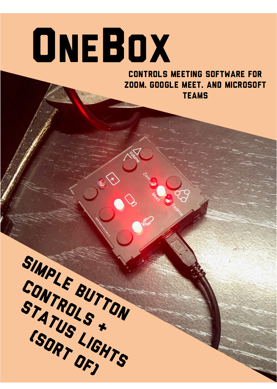
Online meetings have taken over the world it seems. And as a teacher, I alternate between running classes and being an attendee in my bosses and colleagues’ meetings. But there are so many platforms, and each one operates a little differently. I wanted to have an easy control that I could use while attending all meetings, and that would keep me aware of my camera and mic status.
That's where this box comes in. The purpose is to have command of all the frequently used camera and mic actions for my most frequently used online platforms, but just as a button control. And I have a set of LEDS that let me know the last status of my Camera and Mic.
Most online meeting software has "Hotkey" combinations that can trigger actions like muting, chat, video toggles and other useful things. When this is plugged into your computer, the computer sees it as a keyboard. So every button just sends out a string of keyboard hotkey commands used to control your meeting.
This Project might look intimidating, but it is actually quite entry level. You can do it!
- Order your circuit boards (PCBs) by downloading and sending the zipped Gerber files to a board house. You'll get the exact same boards as I have, maybe just in a different color.
- Order your buttons, resistor, LEDS, and microcontroller online with the supplied Bill of Materials(BOM).
- Solder them all together following the instructions and silkscreen orientation.
- Follow the step-by-step instructions and download the programming software (IDE) and use that to upload the pre-written and supplied code to your very own OneBox.
You don't need any programming skills, just the ability to follow steps in order, and learn to solder. If you have soldering experience, all the parts and the IDE ready to go, it should take you about half an hour to assemble. If it's your first time, it will be longer...
Because this was my very first Arduino programming project, (for real!) I also had to learn what I was doing. Planning to share this, I made a ton of notes in the code to explain what is happening. This should make it easier for any fellow noobs to pick up, and easy to change as well. All these notes will help you find the lines to easily change if you are using other platforms like Discord, or GoToMeeting. But you will need to also relabel the top.
Last of all, most Hotkey combos only work on the Desktop Apps of the programs. I use the desktop apps, and that's what this was built for. So if you only run meetings in a browser window, there is no guarantee all these will work. In fact, it for sure will not in some situations
Supplies
Arduino pro Micro
6x pushbuttons
1x bussed resistor
2x header s
6x LEDS.
PCBs
USB to USB micro cable
Solder, soldering iron, and safety glasses
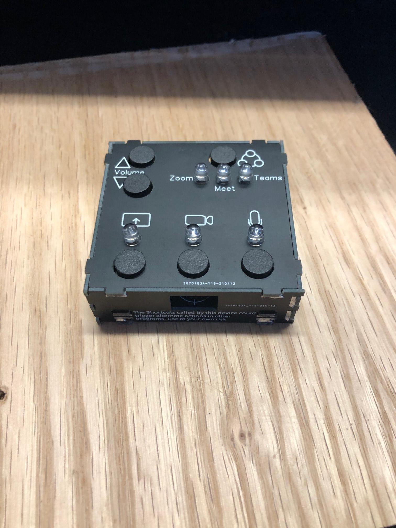
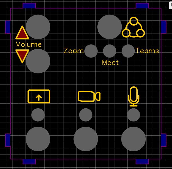
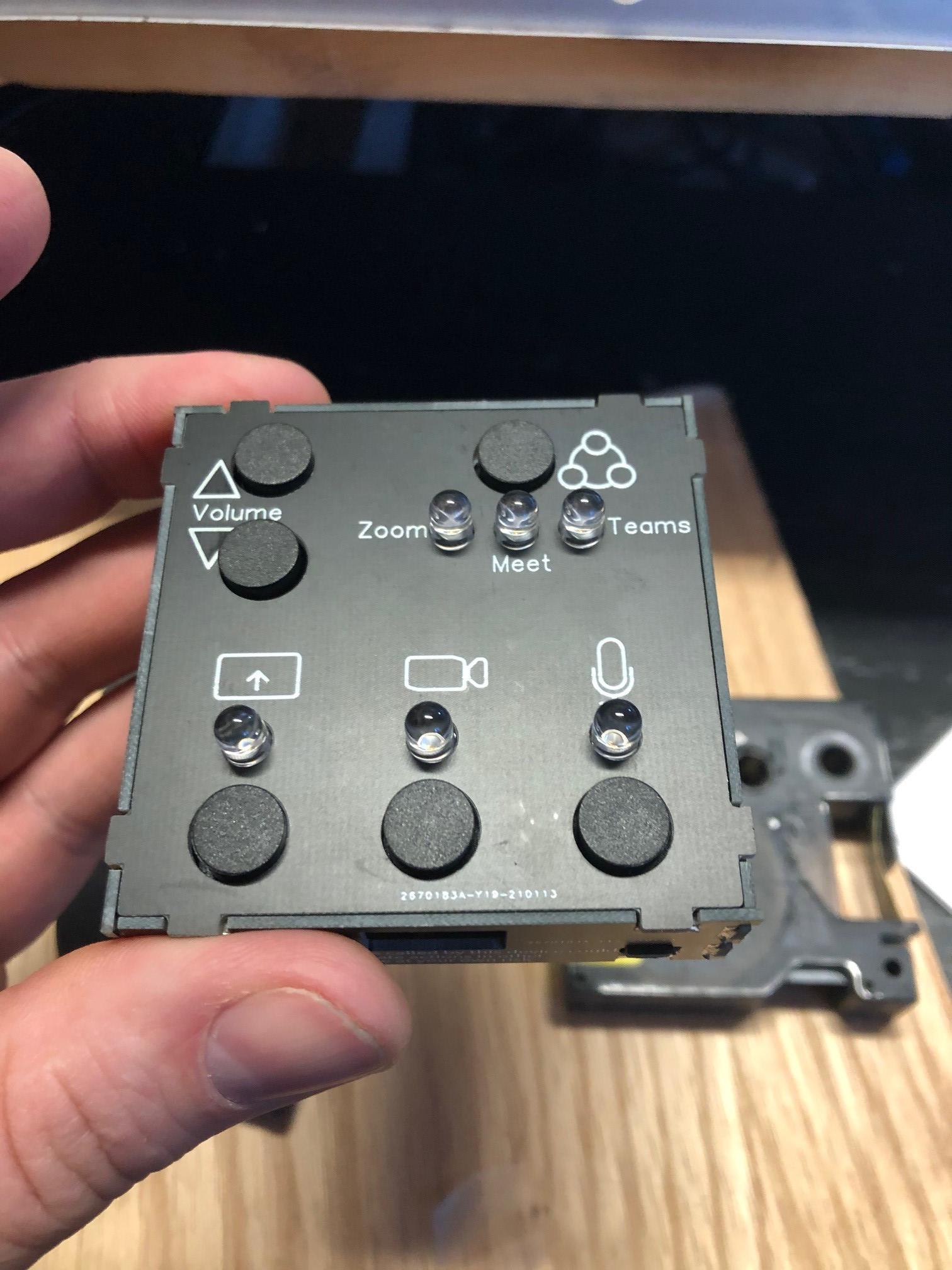
What Do the Buttons Do?
On Zoom Mode, this has the following operation in an active meeting:
Whenever any button is pressed, this will first call the Zoom window to the surface – but only if it is BEHIND other applications, not minimized to the mini-window.
- The “Mode” button can be used to bring the meeting to the surface but adjust nothing (Short Click), or end the meeting. (Long press)
- The “Mic” button can be used to toggle the mic on (Short Click), mute all participants (Long press), or raise your hand (Double-Click).
- The “Camera” button can be used to open the participants panel (Short Click), toggle the video (Long press), and change the view from speaker to gallery (Double-Click).
- The “Screen” button can be used to freeze your shared screen (Short Click), or to toggle screen sharing and the panel (Long press).
Double-clicking the mode button will just move you to the next mode.
On Meet Mode, this has the following operation in an active meeting:
- The “Mic” button can be used to toggle the mic on (Short Click).
- The “Camera” button can be used to toggle the video (Long press).
These are the only Hotkeys available I could find. Google Meet is limited.
Double-clicking the mode/power button will just move you to the next mode.
On Teams Mode, this has the following operation in an active meeting:
- The “Mode” button can be used to end the meeting. (Long press - Also this was a last minute add and was not on my silkscreen. It is on yours)
- The “Mic” button can be used to toggle the mic on (Short Click).
- The “Camera” button can be used to toggle the video (Long press).
- The “Screen” button can be used to toggle the screen sharing panel (Long press).
Teams has fewer Hotkeys available than Zoom, but still quite a few. Double-clicking the mode button will just move you back to the first mode.
The Volume buttons are pretty self-explanatory. But if you press both simultaneously, it will Mute your speakers/headphones.
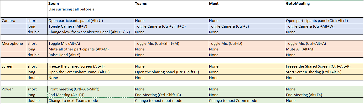
If you don't use one of these software pieces, you can easily change the calls to other programs. The chart above include the GoToMeeting hotkey combos that you could substitute. Or create a bigger version with 4 modes! (You would need to add one mode LED physically. The rest is code in software...)
Project Background

Back in April 2020, "elliotmade" put up an awesome Instructable on a Zoom Physical Mute button. https://www.instructables.com/Zoom-Meetings-Physi... Looking at all those commenting and the projects I have seen since then, I think that inspired a lot of us. I read through it, but didn't have the time to dedicate to making one, and our university wasn't using the Zoom platform. And then in Mid-November "p_leriche" posted another on a zoom control box. https://www.instructables.com/Zoom-Meetings-Physi... My workplace had just announced they would be changing vendors and adopting Zoom for the new year, so I figured I had better get something together to make my life easier.
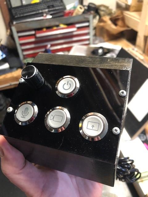
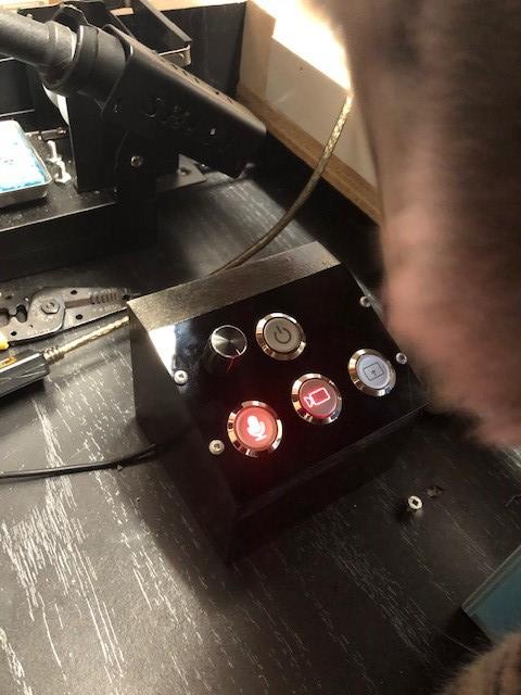
I liked aspects of both the previous designs on here, but I wanted them to crossover and also had some ideas of my own I wanted to incorporate. But I had never yet tried doing anything on Arduino or in the IDE. So I buckled down and got into it. Having a technical background helped, but I found that overall Arduino was as simple and fun as it is acclaimed to be. I bashed ideas together from both of them in the code and figured out how to run the lights. Then I made an initial zoom-only model using lights, buttons, wires, and boxes. That took a bit and I knew it could be all streamlined by mounting onto a PCB. You can see that Zoom-only setup above.
I looked at small, cheap boxes to case this project. But those still also require planning, aligning, drilling, labelling, cutting and other modifications. That all takes time, and I don't have enough of that. And drawing a circuit board is simple and quick, and PCBs under 100mmx100mm are really cheap. So I decided to make my entire case out of PCBs with solder tabs and all labelling done on the silkscreen. Soldering is a fast way to permanently put one of these together.
Circuit Design
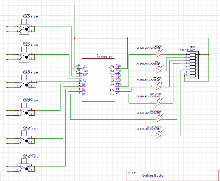
My circuits and boards were all drawn in EasyEDA, since that is what I've been using for the last few years.
Something to be aware of though if you are just starting design - EasyEDA will import working design files from other design suites, but it can only export those working files to itself or Altium. If you start with it, you cannot convert out and this will limit future builds or conversions of yours! I wish I had more thoroughly researched a few years back and started with Eagle, but I've got a lot of libraries and work on Easy EDA by now and will stick with it. Thankfully the final output files are not proprietary, and are generated as Gerber files though.
The project is built around the Arduino Micro Pro since it has direct USB communication capabilities. It also has the ability to utilize internal "Pull-up" resistors, so there are fewer external circuit components needed. So each button only needs to switch to common (ground). No external power will be needed, as this will all be powered through the USB cable.
I decided that I needed 6 buttons at maximum. Some of them would have multiple modes though, depending on the button press (Short, long, or double-click)
- Mic control
- Camera control
- Sharing control
- Mode select
- Volume Up
- Volume Down
LEDS were also incorporated. I wanted to know my Mic/Cam/Share states, as well as my mode I was in. This required 6. They all shared a bussed resistor. (I could have used an RGB LED for the mode, but the concept here in this project is creating a simple, accessible design and color mode is not going to cut it for someone color blind.)
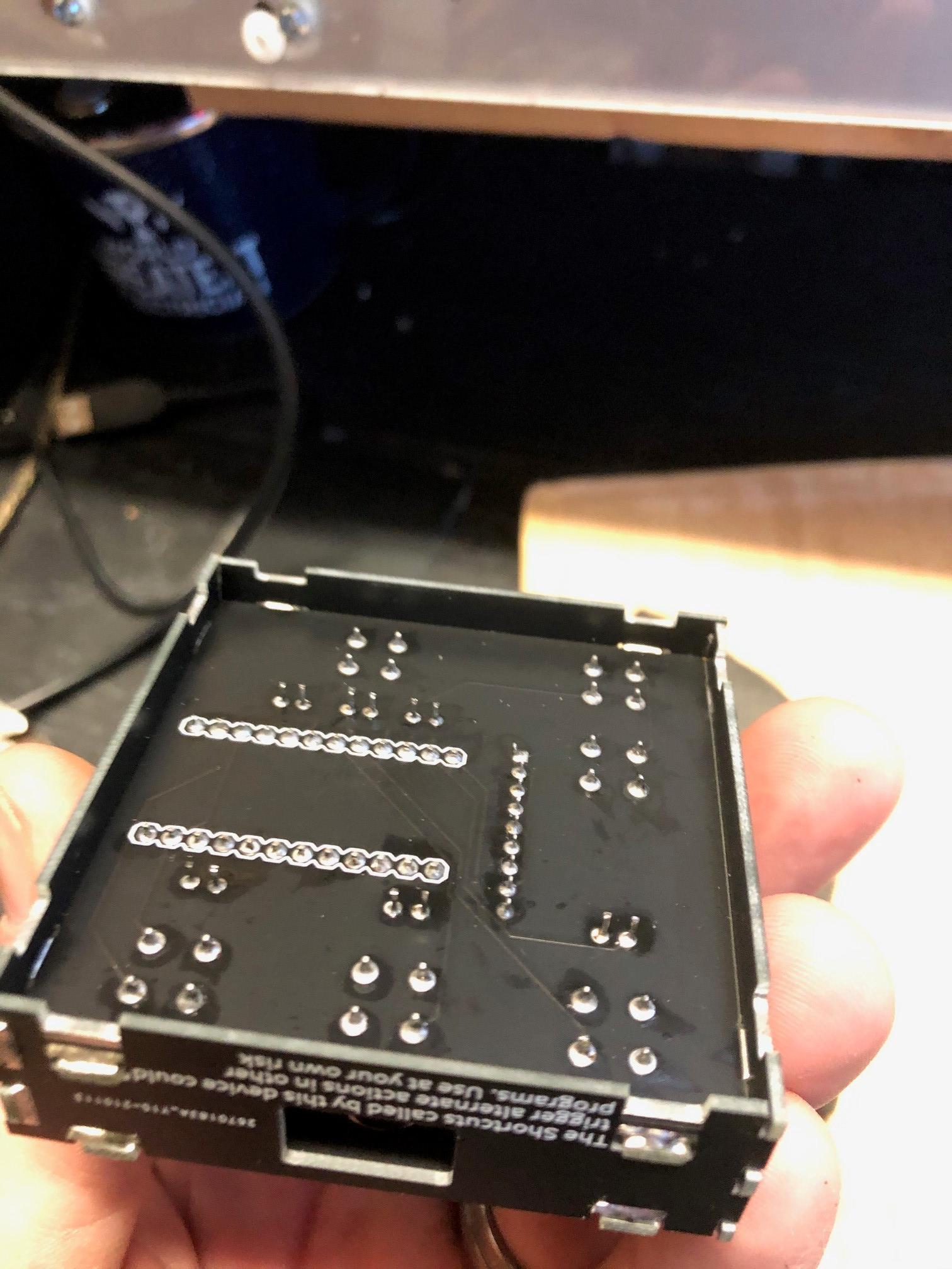
Through-hole Design Boards
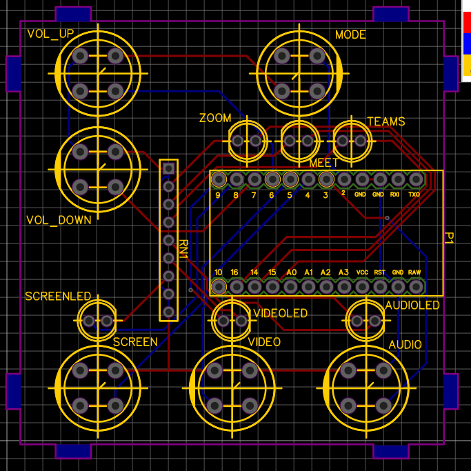
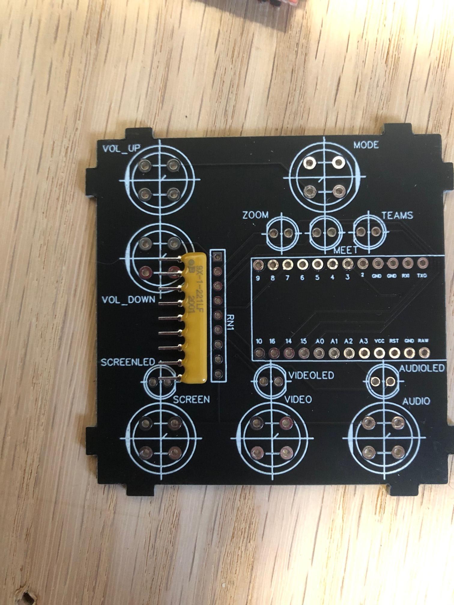
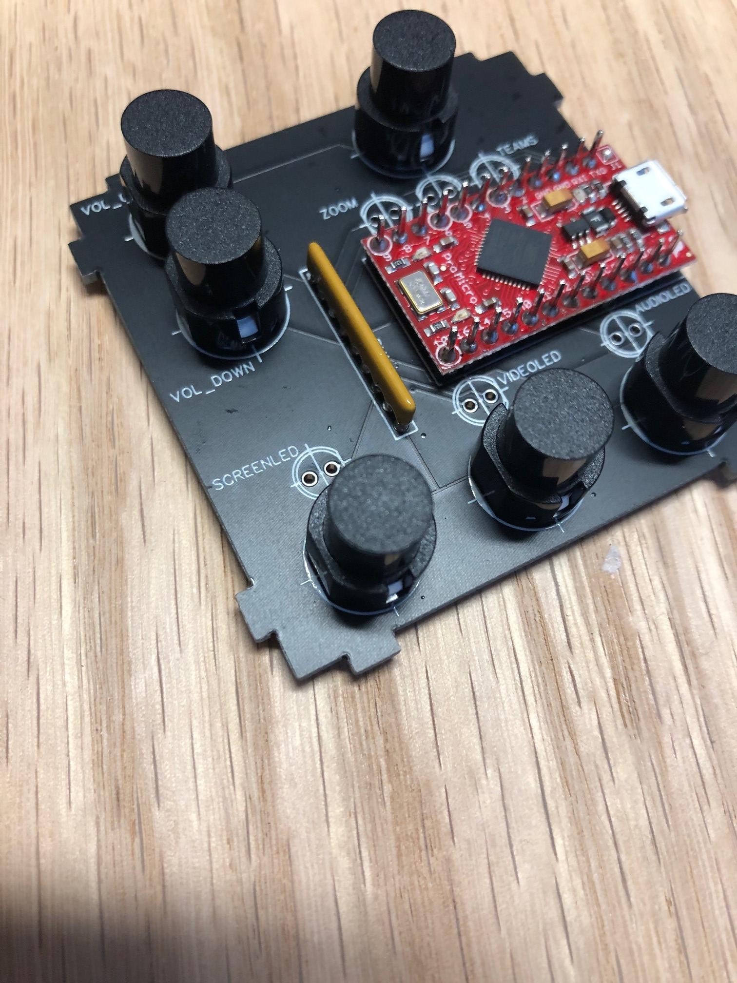
This is an open sourced project. So I wanted to make it easy to solder up. Although I have created and soldered a lot of my own SMT boards on other projects. But those are difficult to solder without some practice. So I chose through-hole for this, as that is in the realm of any hobbyist with an iron. I fit the components into a comfortably small board, ensuring it was square (64x64mm). (I wanted it to be square so that all sides could be the exact same.)
All components are to be mounted to the board topside, and there is a full silk-screen to use for aligning them. The tabs have a bare solder pad on the bottom.
(You need one of these for each box you might build. Also, this board is all you would need for bare-bones operation on this project. If you don't want to build the box, you could just run this bare, sitting on your desk. Not recommended, but possible until you short it out over a staple or paperclip…)
I ordered these in 1.6mm thickness and double-sided
The EasyEDA files for this board are available on Github here. They are a JSON type. https://github.com/Memestra/OneBox/blob/main/PCB_...
The Gerber Files for this board are also available on GitHub here as a ZIP file. https://github.com/Memestra/OneBox/blob/main/Gerb...
Top Board (Lid)
The top board was aligned with the circuit board. It has the necessary cut-outs for the buttons and LEDS, as well as the silk screen.
You need one of these for each box you might build. Also your PCB manufacturer may be very confused on these. I fielded a lot of questions before they made these for me. So I ended up putting a bit of copper on each side so they would just go ahead and make them without the confusion.
I ordered these in 1.6mm thickness and double-sided as the manufacturer was really struggling to understand my file and rejected the files initially.
The EasyEDA files for this board are available on Github here. They are a JSON type. https://github.com/Memestra/OneBox/blob/main/Top_...
The Gerber Files for this board are also available on GitHub here as a ZIP file. https://github.com/Memestra/OneBox/blob/main/Gerb...
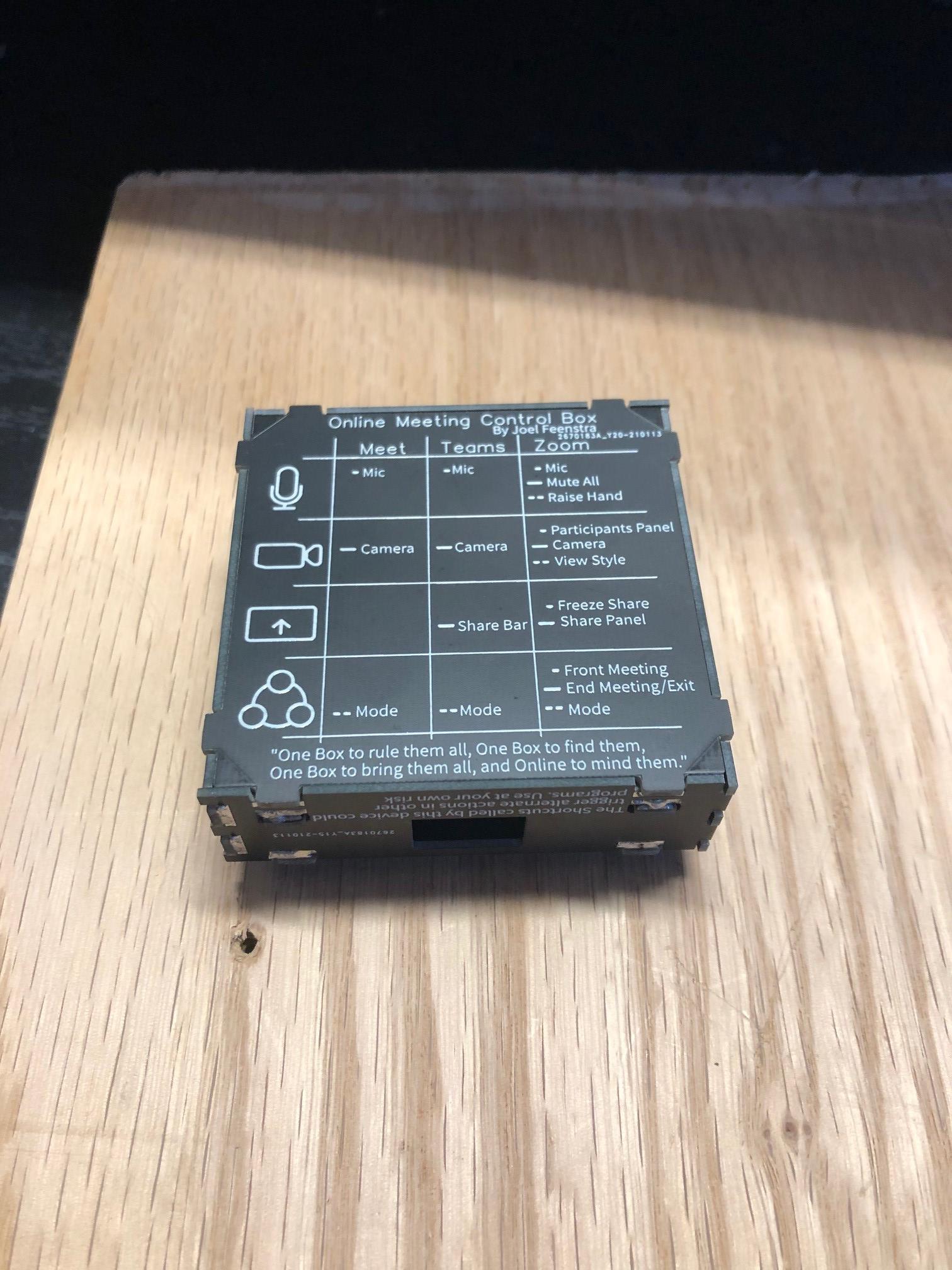
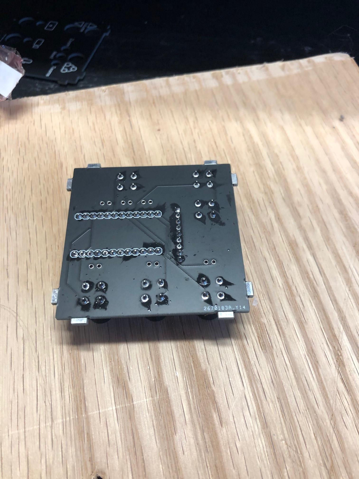
Bottom Board - Legend
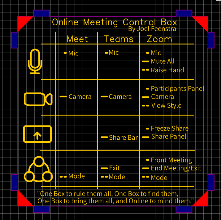
There are not cut-outs on the bottom board. The purpose is to protect you from shorting the bottom pins of your PCB if you would place it onto something metal (pens, paperclips, etc.). It also has a legend of all the commands programmed to send with this. Each is identified with an icon (dot for short press, dash for long press, and double-dot for double click.)
As you can see, Zoom has the greatest amount of useful hotkeys that can be called. It's actually kind of fantastic to use for teaching.
At the bottom, there a small poem. It is in the style of the infamous ring-verse, from Lord of the Rings. Like 'the One ring', this box too has great power and can make you invisible to others. Also I just really like LoTR.
You need one of these for each box you might build. Also your PCB manufacturer may be very confused on these. I fielded a lot of questions before they made these for me. So I ended up putting a bit of copper on each side so they would just go ahead and make them without the confusion.
I ordered these in 1.6mm thickness and double-sides again just due to the manufacturer confusion.
The EasyEDA files for this board are available on Github here. They are a JSON type. https://github.com/Memestra/OneBox/blob/main/Bott...
The Gerber Files for this board are also available on GitHub here as a ZIP file. https://github.com/Memestra/OneBox/blob/main/Gerb...
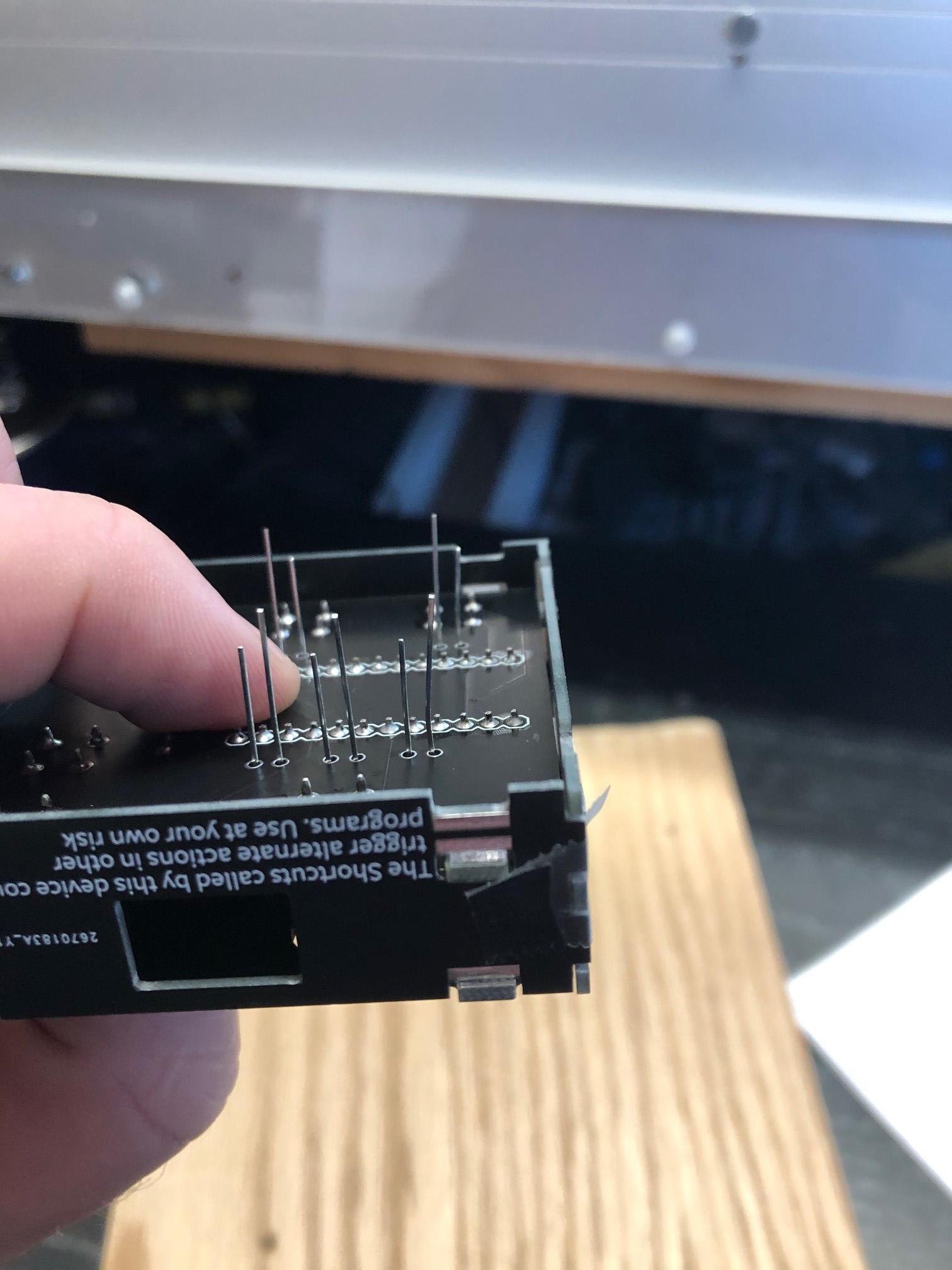
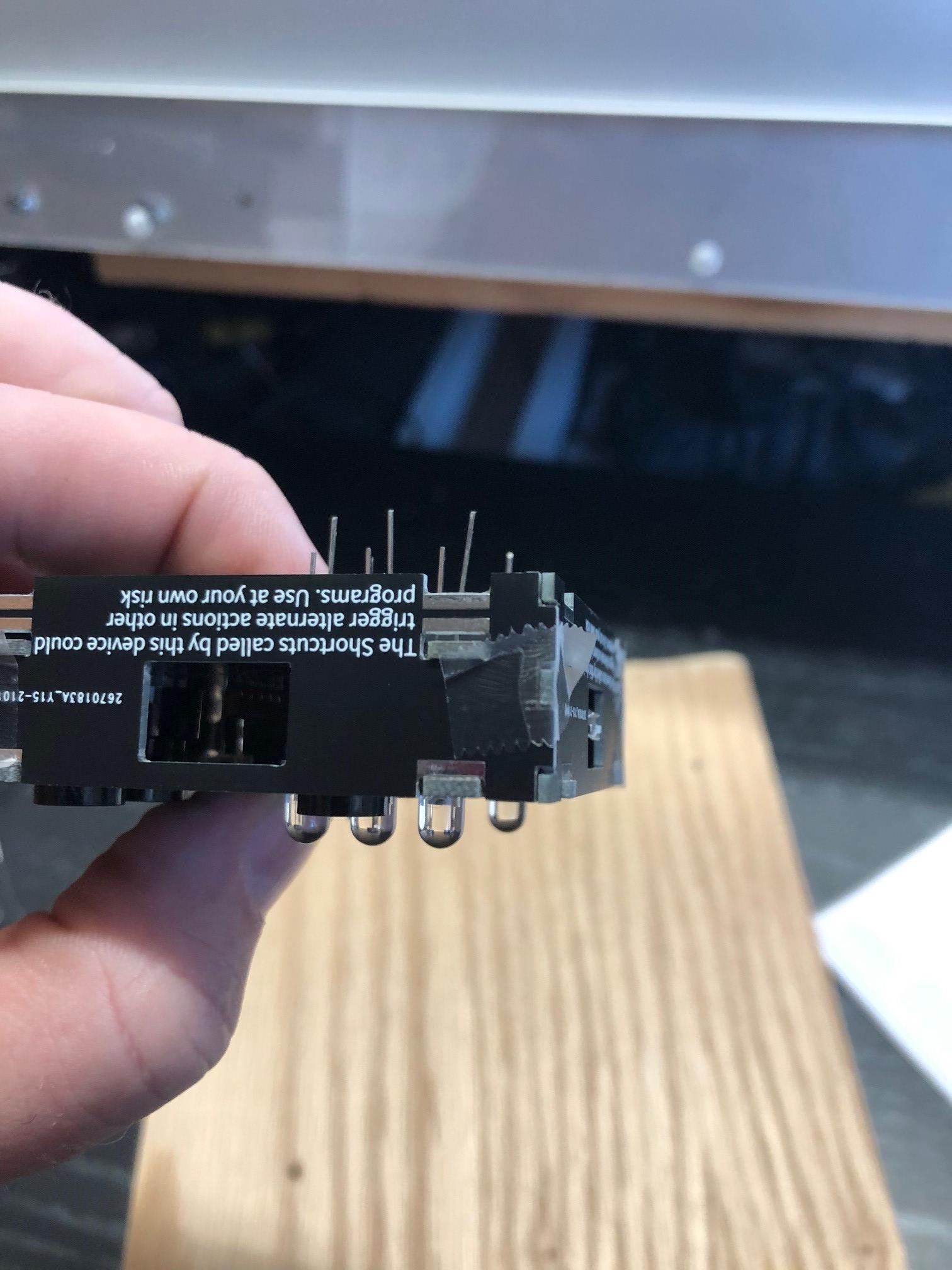
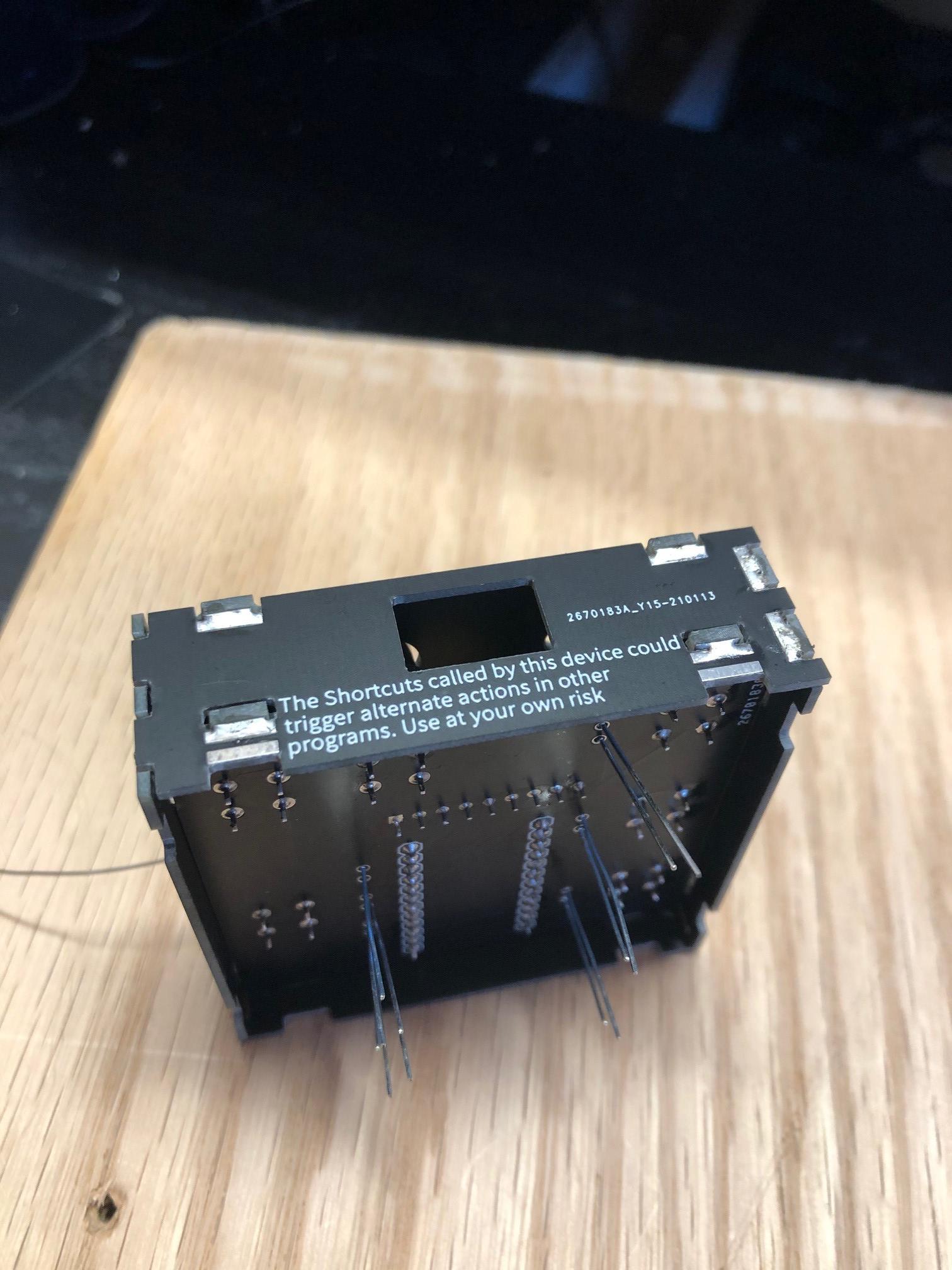
Side Boards.
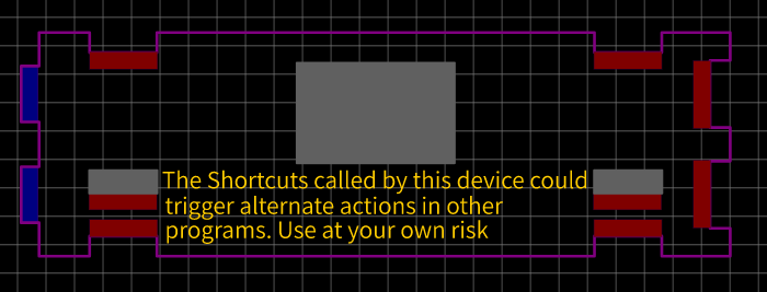
All 4 sides are identical in size. So I made only one design, cut a hold for the USB socket, and put a warning on the side. This is really just a keyboard and it will send those key combinations out with a button press, no matter the open and active program.
You need 4 of these for each box you might build.
I ordered these in 1.2mm thickness. These legit need to be double-sided for the corners.
The EasyEDA files for this board are available on Github here. They are a JSON type. https://github.com/Memestra/OneBox/blob/main/Side...
The Gerber Files for this board are also available on GitHub here as a ZIP file. https://github.com/Memestra/OneBox/blob/main/Gerb...
Part Order
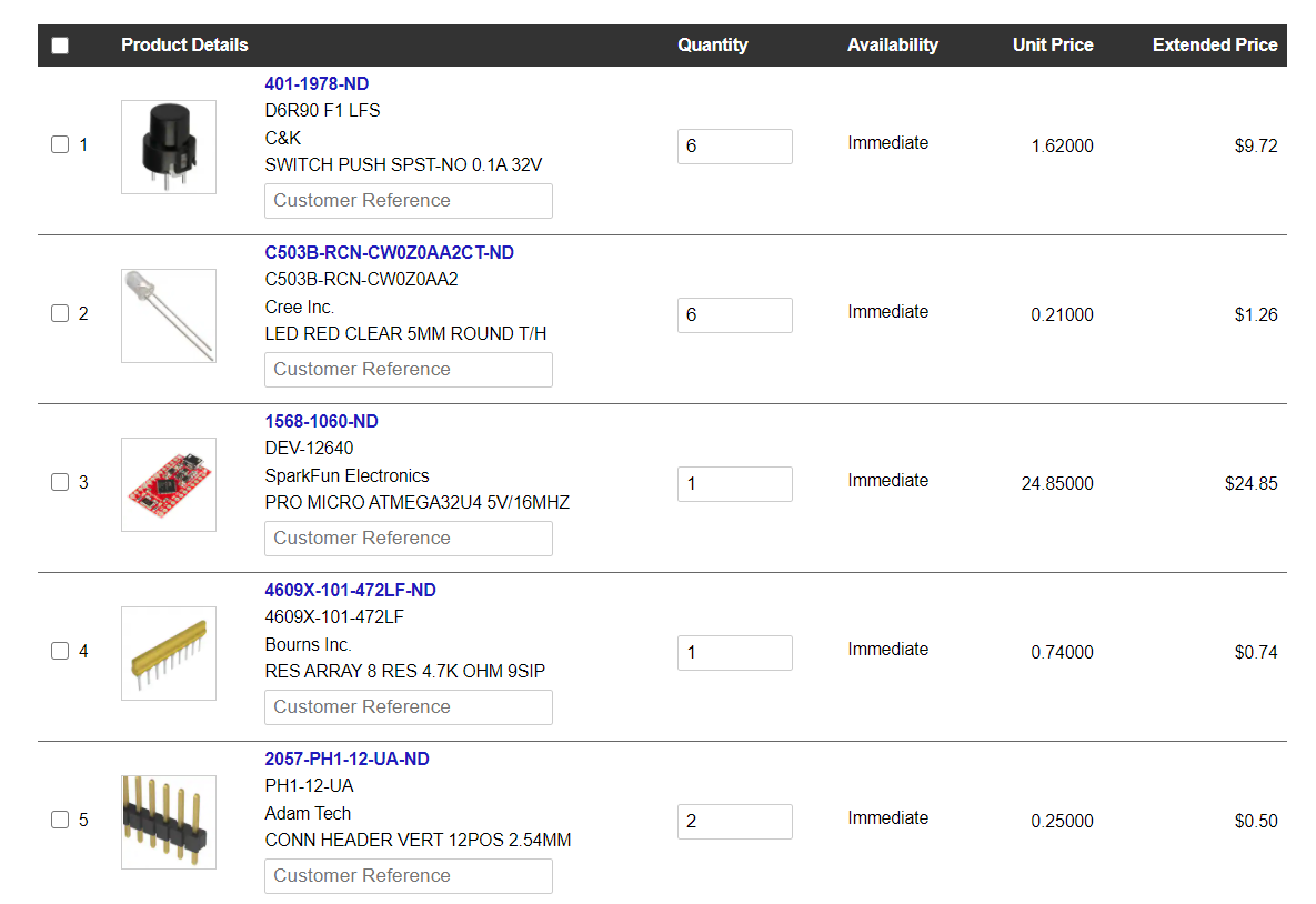
I ordered my parts from Digikey. I did not get headers though, as I have a lot kicking around here.
If you want, you can upload the entire BOM to your Digikey account and get the exact parts I have. Please buy and use the genuine SparkFun, they have put a lot of work into it.
Although the footprint is a 5mm square, careful if ordering different buttons. Refer to the datasheet and make sure they are dimensionally the same. They need to have the same height to work with the casing I designed.
Edit - (I actually just changed my bussed resistor to a 10k Ohm. The 4.7 k is fine, but I wanted it dimmer. Still works fine and is a nice dim light now.)
Downloads
Soldering the Components to the PCB
The first 5 minutes you spend soldering are challenging. But after that, you'll find it really isn't that hard. Start by setting up a fan to blow the fumes out, and some safety glasses in case you splash hot solder.
You need a soldering iron to build the circuit, as well as the box. I set mine for 380 degrees usually, except in winter here in the garage where I need 390 to makeup for the Canadian winter ambience.
For solder, I'm using a 63% Tin, and 37% lead content and flux core solder. This is referred to as 63/37, and is the most common type. It is "Eutectic" which means it is very sudden in its change from solid to liquid. During soldering, the flux core melts, and as it does it cleans the leads and pads. It also helps the melted solder to flow to coat and connect all parts.
During soldering, you need to maintain a good, clean tip on your iron to evenly conduct the heat out. I regular melt some solder onto the tip and clean it on a wet sponge. Once the tip is clean and the iron is heated, here are the basic steps.
- You wedge the heated iron up against the component lead and the terminal ring on the board as you want both to heat at the same time.
- Watch for the coating on the terminal to "Wet", which is the fancy term for "Melt and get shiny looking". (This should happen in under a second or two, depending on ambient temperature.).
- While keeping the iron against the lead and terminal, then apply solder against the iron tip and as soon as it begins melting, quickly draw it in a half-circle to the opposite side of the lead. It should melt as you are doing so and flow to fill the joint. This should only take a second or so as well.
- Pull back the solder wire first, and then the iron. Don't disturb the joint, and in a second or so it should go dull which means it has solidified. The final joint should look like a mini volcano.
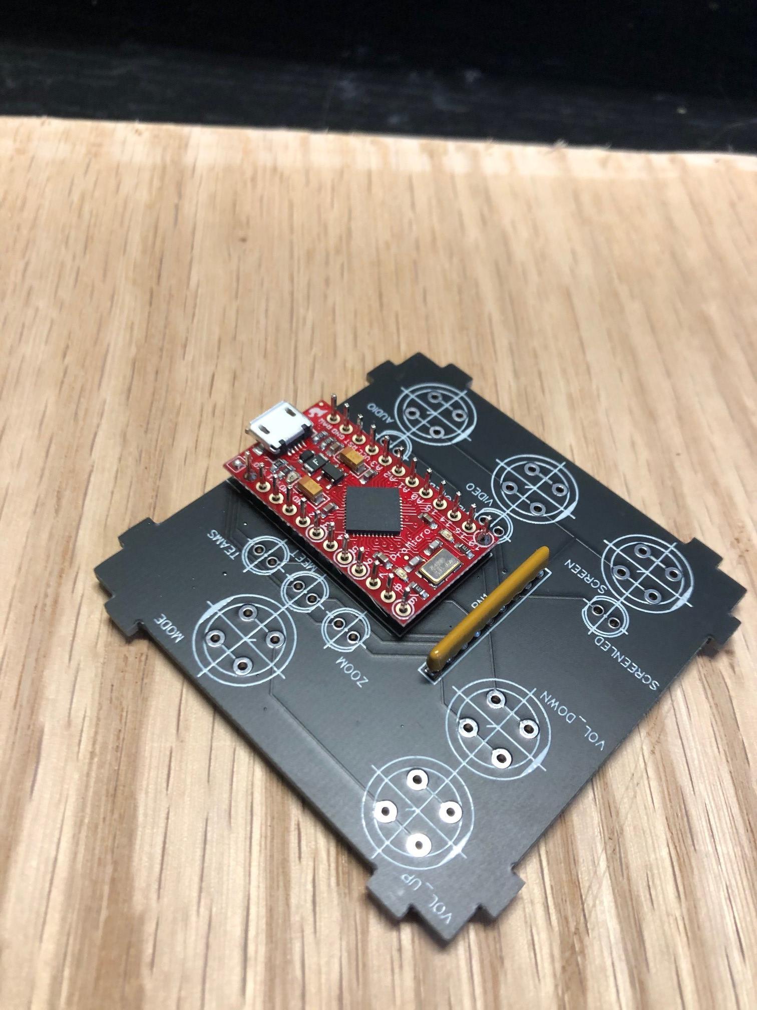
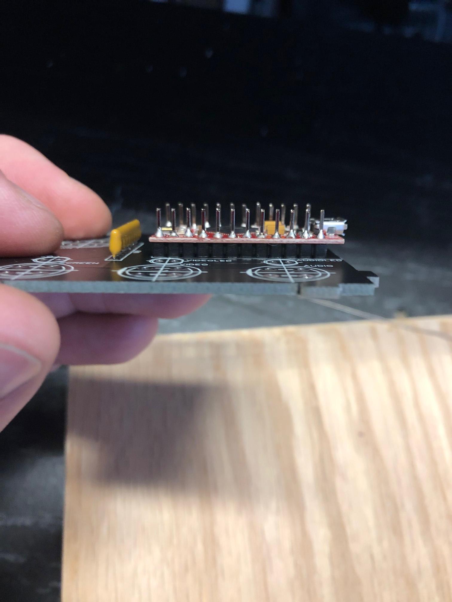
I always start by soldering on my shortest components first. Put them through the holes on the board, and flip the board and rest it on your bench. Solder them, then do the next tallest etc. This way gravity holds the board in place against the components as you work. My order I used on this board was first the bussed resistor, (Although the dotted end of the resistor array should be aligned with the square pad, it won’t matter as I’ve applied ground to either end. Don’t stress it, I’ve made it easy.) then the Pro micro on the headers, then the buttons.
You can also use sticky tack and tape to hold pieces temporarily. This can cause static issues on some sensitive items though and cannot always be used. But we have nothing that twitchy on this board so go for it if you need. It is way easier to solder with the board well anchored.
While soldering components, do not solder on the LEDS yet. Do everything else. We do them in the next step.
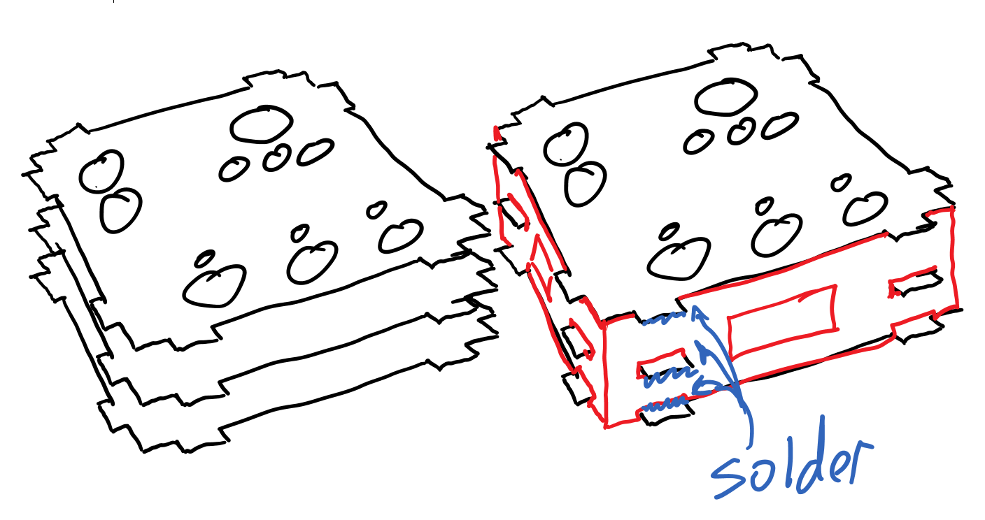
Soldering the PCB Case.
Except the LEDS, your board should have all the components soldered in place before you begin this step.
- Place your LEDS through the holes on the board and align each flat side with the silkscreen. Don’t solder them yet though.
- Now take 4 side boards and place the around the edges. Use tape to hold them in place for now.
- Then take the top board and tape it on, with the silkscreen facing out. Make sure the LEDS are loose underneath.
- Make sure all joints are square and butted tight. Readjust the tape if needed.
- Now one at a time, remove each piece of tape and then solder all tabs underneath it.
- Once all tabs on the tops and sides of the box are done, then push the LEDS through the top of the board. Then flip the board and support the edged so you solder them in to the board while they protrude out the bottom.
- Trim any last leads.
- Solder on the bottom plate.
* IMPORTANT. All the solder I have used has lead content and some is exposed. California would not like it and would put a warning on for sure! Although the chances of skin contact are low with all solder on the side, I also don't want to touch lead more than is needed. So I will be taping off the LEDS, USB terminal, and buttons, and shooting a coat of clear coat over the entire box later. You can also just coat any exposed solder with nail polish if you want. But do something to protect yourself from long-term lead exposure.
Someone just told me that you can also use epoxy like "JB Quick Weld" to join the box tabs instead of soldering. I don't know how that bonds to the solder pads, but if it does, absolutely go for it. There is no current going though those tabs and all you need is a mechanical bond. If you try it, let me know if it does work.
Setting Up the Arduino IDE
I'm going to walk through this like you have never done anything on Arduino before. Because some of you have not and are intimidated by it. And as of December, I had not either. But now it's a month later, I'm still not a real scientician and I can do it. So I'm sure you can too! Just follow each step below in order.
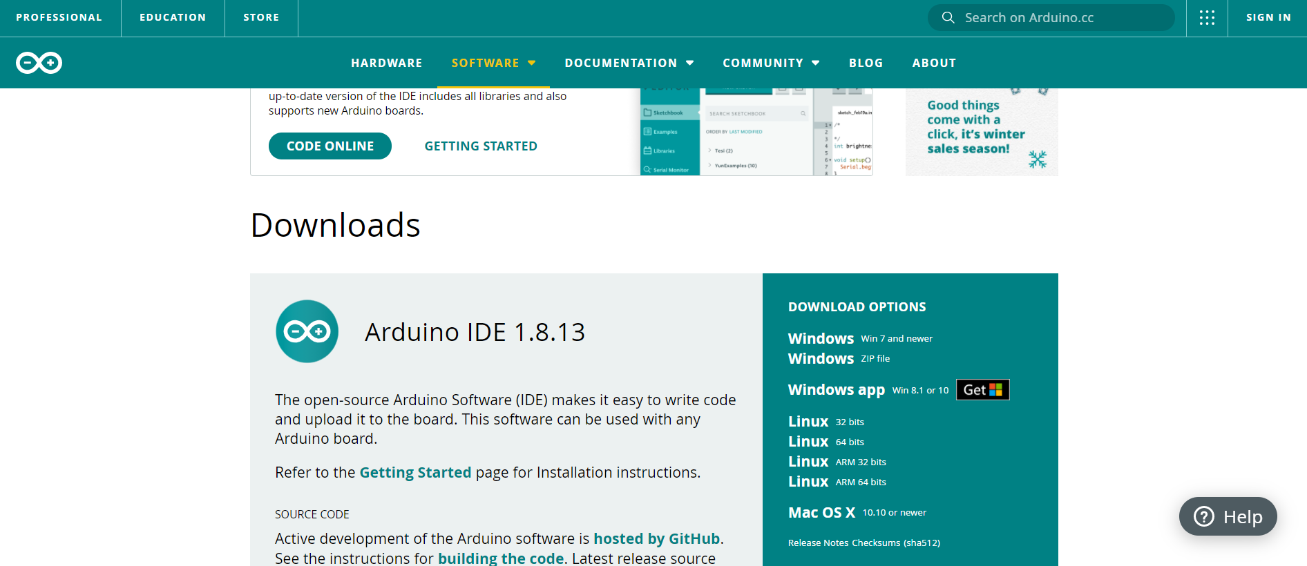
- Let's start by going to the Arduino Software site https://www.arduino.cc/en/software
- Click on the "Arduino IDE" and download that and install that. Don't worry about the version, just go with the current one posted.
- Sparkfun is a separate company from Arduino. So the ability to use their boards is supported, but not a default part of the Arduino IDE program. We need to tell Arduino where to find "Sparkfun Board libraries" so the IDE can then communicate with the board we are using.
- Start by opening the Arduino IDE program. Then go to the "File" tab, and then down to "Preferences". Click that.
- A new popup window should have launched. Near the bottom of that, there should be a white box that says "Additional Boards Manager URLs" We will use this box to direct our Arduino IDE to the web address where it can automatically download and install the libraries we need.
- Right click this link and "Copy Link Address". Then paste it into that the "Additional Boards Manager URLs". https://raw.githubusercontent.com/sparkfun/Arduin...
- Then click OK. And then close Arduino.
That's it. We have the IDE installed and ready to connect with the Sparkfun board. IDE stands for "Integrated Development Environment" and acts like a garage with basic tools where we can take code into. There we can open it up to see the guts of the code, take it apart, bolt on extras, and generally tinker with it. We also need this to send the finished code to the microcontroller.
We can also add specialty tools (libraries) to this garage (IDE). We will do that in the next step.
Adding the Libraries
Now we need to add some libraries to our IDE. Libraries are just some prebuilt specialty tools and instructions that we can tell our Arduino to use to complete the task we are giving it. (Remember how the IDE is like a garage? These are like that set of special sockets you would only buy and add to your garage if you needed them for a very specific task you plan to do. Not a tool everyone needs everyday or all the time, and only added if needed.) This project will need us to use two libraries.
The first library we will add in will be the "OneButton". This will allow us to multi-mode our buttons and uses the internal pull-up resistors.
- Click on the Tools tab
- Click on "Manage Libraries"
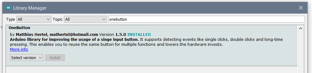
- A Popup will have opened. In the top there will be a search bar. Type in OneButton.
- The search result should return a library named OneButton by Matthias Hertel.
- Click install.
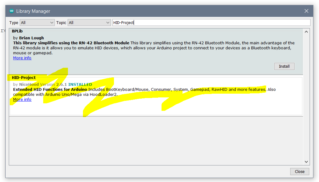
The next library we will need to add is called "HID-Project". It is a library that helps our Arduino to act as keyboard with specially commands. It will allow us to access keystrokes and audio commands.
- Click on the Tools tab
- Click on "Manage Libraries"
- A Popup will have opened. In the top there will be a search bar. Type in HID-Project.
- The search result should return a library named HID-Project by NicoHood.
- Click install.
We now have the IDE ready with all specialty libraries loaded. Let's do something with that now.
Uploading the Code
Now let's get that code into the box.
- Start by downloading the My_Precious.ino file.
- Save it to your desktop.
- Double click on it to open. Arduino will balk and say it needs to be in an appropriately named folder. Click OK so it can do its thing and create that folder.
- You should now have the code open. Next we need to tell the Arduino program what board we are planning on sending this code to.
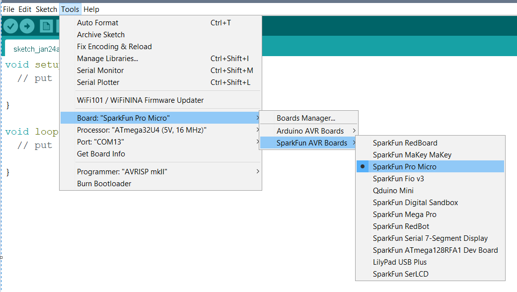
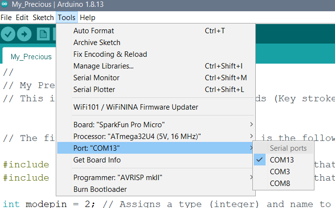
- Open the Tools tab. Go to Boards, then to SparkFun AVR boards, then select the Sparkfun Pro Micro as the board type. See the first picture.
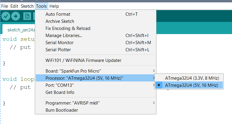
- You need to tell Arduino what kind of processor the Pro micro is running so it can include that information when it sends the code to the board. Go to Tools, then Processor, then select the ATmega32U4 5V 16 MHz model. See the second picture.
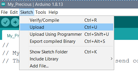
- Plug your Arduino in with the USB micro cable.
- Open the Sketch tab, then click on upload. See picture 3.
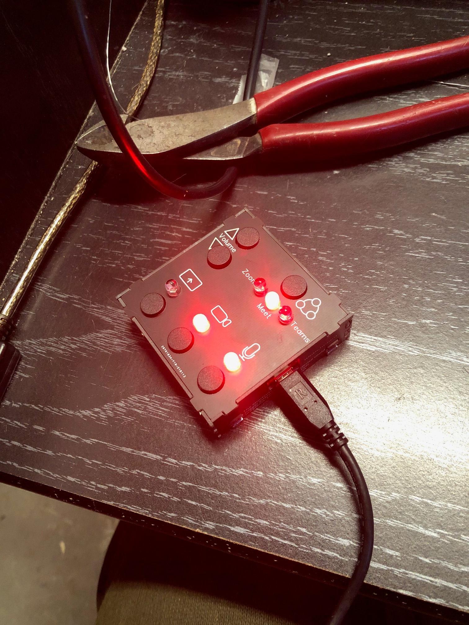
The code should then go through a process called compiling, and then upload. A status bar on the bottom of your Arduino window will tell you about it, and will say Done-Uploading when complete. LEDS should be flashing on the circuit board while the upload is happening, and then the Zoom LED should light once it has started.
If the IDE cannot find the board and successfully upload the code, try another port under the Tools tab. See picture 4.
Downloads
What Is the Code?
The code is well commented out, but if this is your first Arduino project, you probably have no idea what is happening. So let’s go over the 3 main sections of the code.
Section 1 - Mapping – It is literally like ancient map-making, where someone would physically describe a place (in a drawing) and then name it as well so that it could be referred to and located by others. This is the first section where we will tell the board about all the things we have connected to its pins, and give each of those connections a name. We will also tell the Arduino about the type of data each name represents by defining it as Boolean, or Integer. This is also where we tell the Arduino to include the libraries into the code, as well as where we need to set names for each of the OneButton controlled buttons. Some of it seems kind of redundant, but is needed for clarity. This section ends at the “void setup()” line
Section 2 - Setup – This section is used to get our Arduino ready to start running. Just like a runner setting up on the starting blocks. We take each of those pins we gave a name to in the mapping section, and now tell the Arduino to get ready to use them as outputs, or inputs. We also tell the Arduino if those outputs should be starting high or low, and we tell the libraries to begin their internal processes. This section ends at the “void loop()” line
Section 3 - Executing - This is what most people refer to as the “Loop”, although in this program we also do some one-off tasks outside the loop with the OneButton library. (Those are called for with the Tick commands in the loop though) It is like a never-ending list of chores that the Arduino needs to go through. It checks the conditions listed for each task, then executes it if those conditions are met. Then it moves on, all the way through to the bottom of the loop, and then goes back to the top and restarts. This is where all the “If this, then do that” parts of the code are.
You can read through the comments on the Code. Experiment with your own changes. (Careful though, a single character change can error the whole program.) And if you destroy yours beyond recovery, just get a fresh copy here.
How Do I Used the Finished OneBox?
In order to use this, all you need to do is plug in the USB cord for this into any Windows computer. (Although you needed to have the IDE to program it, the computer you are using it on will not need that Arduino IDE. The IDE is only for programming it. Once the OneBox is programmed and the IDE is closed, all computers only see it as a keyboard. ) You can take your OneBox with you to work or school, and plug it any computer. The computer will “See” the device, and automatically download and install a Device Driver. (As long as your organization hasn’t locked that ability out.) This takes only a minute or so the first time you use it. Once that driver is installed, the OneBox is ready for your meeting.
Because this is acting as a keyboard, be careful if pressing these buttons in programs and modes other than Zoom, Meet, and Teams. The keyboard shortcut gets sent to whatever the currently open program is, and that could be disastrous if something in that program uses the same shortcut. Be careful with that. (Except Volume. Volume is good to go everywhere.)
Why All the Delays?
There are a lot of delays in the Code. And there is a reason for that. The processor (Brain) is operating at 16Mhz. So commands that are sent out are literally in the nanoseconds of duration. (That is one-billionths of a second.) These commands can be missed by your computer if you simply use a “keyboard.write” command to send them in. This is a particularly bad problem if you have a slow or busy processor that might not see and be able to respond in time. The other reason these can be missed is if you are connecting these though USB extensions or laptop docking stations. This can act like a game of “Telephone” where fast commands can be lost or corrupted.
By using the “keyboard.press” commands and then a delay, it holds these up for at least 50 milliseconds until the “keyboard.release” command, which is plenty of time for the processor to see them and react. It acts like someone holding down a key. And it is still plenty fast.
Delays like these are referred to as “Blocking Code” as they block the Arduino from doing anything else while it executes a forced wait. These are not always wanted, and could be a problem if we had complex processes that are running in the background. There are ways around this that could poll and store values from the internal timer (called via “millis”) and hold these using that. But that would be overly complicated for what we need, as we are only monitoring these buttons and executing a single command line at a time.
If the delays greatly bother you and your computer can keep up, feel free to remove them in your project, substitute the keyboard.write commands, or change the code completely.
The Status Lights
If you enter all meetings with your CAMERA OFF and MICROPHONE OFF, and then CONTROL THE MIC AND CAMERA FROM THE ONEBOX ONLY, the status lights are fairly reliable.
These lights are a “dumb” output that only responds to your button presses, not the actual meeting software. They do not actually know if your camera and mic are on, rather they are telling you that you have either called for the cam/mic to be on or off, if started from an Off state. For them to actually know 100%, they would need their own specialty software that would be communicating with the Zoom/Meet/Teams software, and sending that data back to the OneBox.
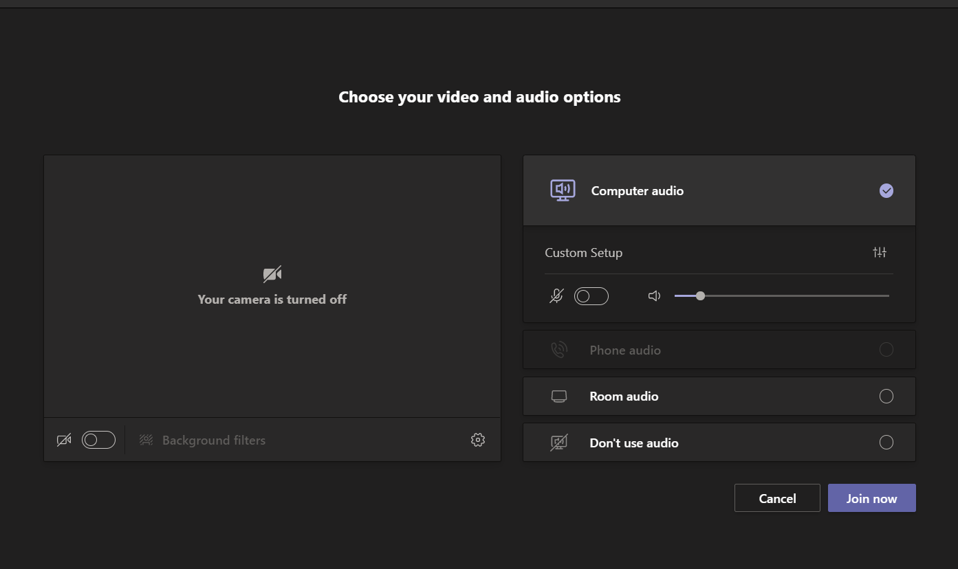
Always verify by looking at the on-screen icon and don’t rely on the lights as absolute. I take no responsibility for any infamous or career-limiting “hot-mic”, “on-camera”, or "shared content" moments you may inadvertently create.
If you find the lights are out of Sync with your actual status, (usually caused by pressing them while not actively in the meeting or when the Zoom window is in the minimized/tiny mode) then use the on-screen meeting controls to sync back up.
These lights are really handy in shared spaces, like home where I teach from for now. My wife and son can see if my camera and mic are on before they talk to me or walk into frame.
Let the Credits Roll...
That’s a lot of writing for me, and a lot of reading for you! Enjoy. And thank you again to the following:
- ElliotMade for piquing my interest with his Instructable and introducing me to the OneButton Library
- Matthias Hertel for creating and sharing the OneButton library
- P_Leriche for his Instructable and introducing me to the HID-Keyboard Library
- NicoHood for creating and sharing the HID-Keyboard Library
Enjoy making and learning! If it's worth your time, please give me a vote in the PCB contest as well if you can spare the 3 seconds for my time on this!