OSOYOO Yun IoT Smart Home Kit
by osoyooproduct in Circuits > Electronics
6955 Views, 14 Favorites, 0 Comments
OSOYOO Yun IoT Smart Home Kit
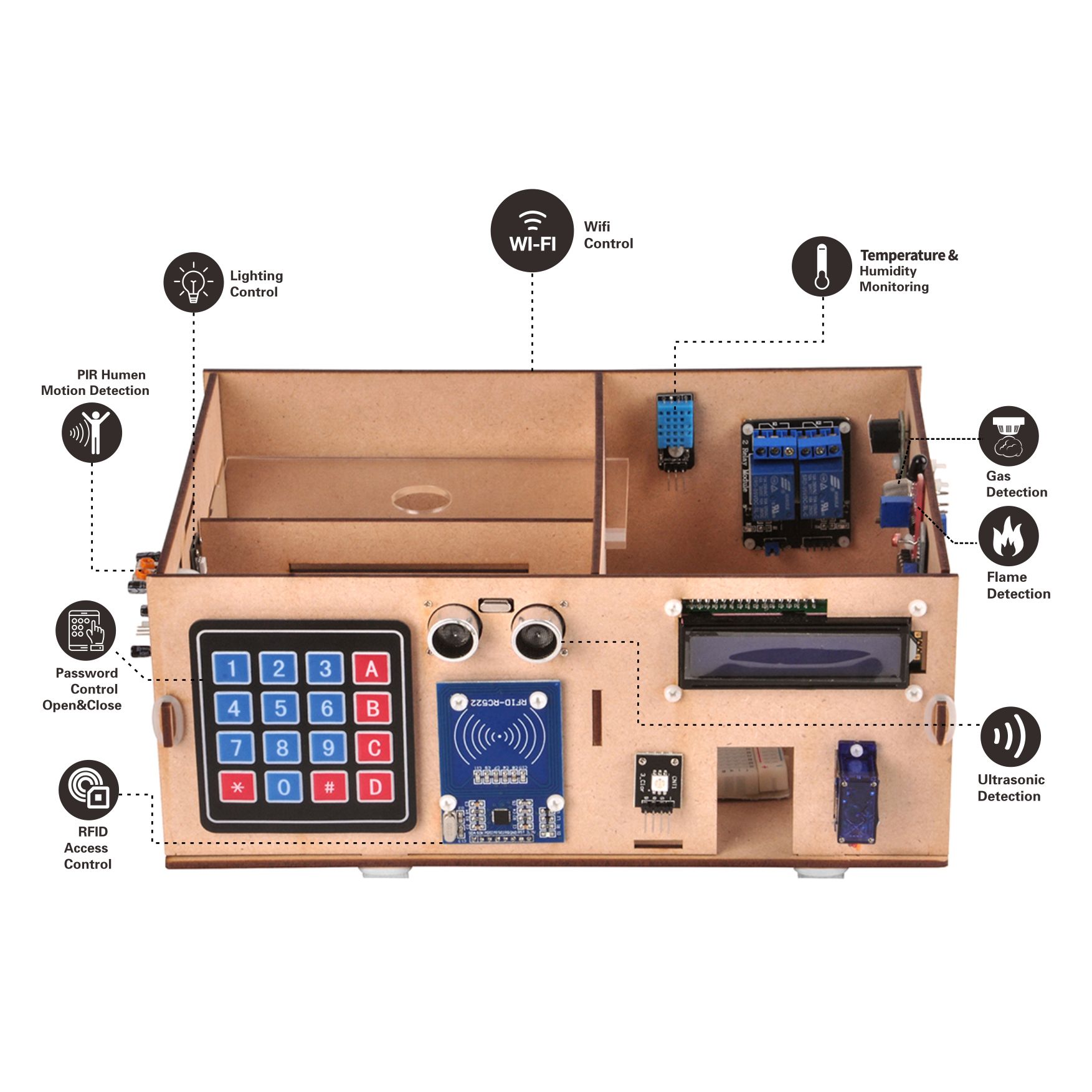
From controlling the room lights with your smart phone to scheduling events to occur automatically, home automation has taken convenience to a whole new level. Instead of using mechanical switches, you can now conveniently control all the devices in your home from your fingertips.
Over here, we will show you how to implement a simple DIY home automation setup using an Arduino microcontroller development kit.
In this Smart Home system, we constantly upload temperature and humidity, light intensity, gas values, flame value, RFID status values, human pyroelectric infrared sensor status values and other data to the Blynk platform at a certain time interval.
With the controller options on the Blynk platform, you will be able to control your remote relay in real time. At the end of the setup, you will be able to turn any electrical appliance into a smart home device, and control it from your smart phone. Its principle is that the Android mobile phone via internet send instructions to make Arduino MCU control action of peripheral module, and read the periphery value of the sensor. It is because of the open source characteristics of Arduino and Android, so we have the opportunity to built future smart home fashion based on it.
Of course, here we only preliminary outline a model of smart home, mainly to provide an introduction to learning. The way to the true smart home is still long.
Preparations
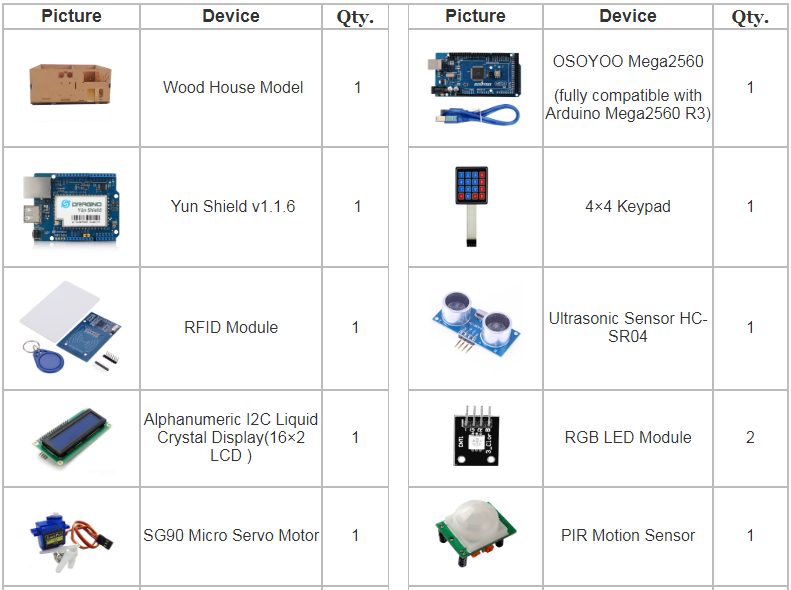
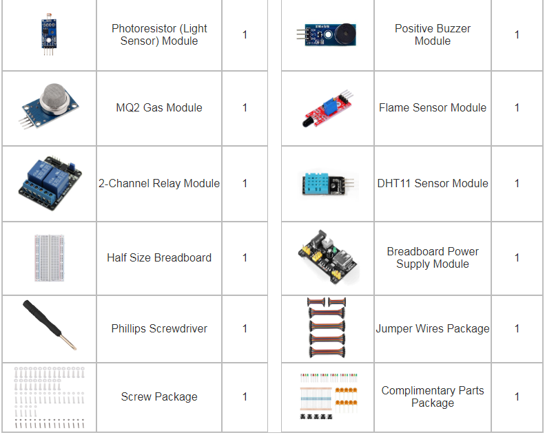
HARDWARE
You can get the harewares from Amazon:
OSOYOO Yun IoT Smart Home Kit (US)
OSOYOO Yun IoT Smart Home Kit (UK)
OSOYOO Yun IoT Smart Home Kit (DE)
OSOYOO Yun IoT Smart Home Kit (FR)
OSOYOO Yun IoT Smart Home Kit (IT)
OSOYOO Yun IoT Smart Home Kit (ES)
OSOYOO Yun IoT Smart Home Kit (JP)
SOFTWARE
Arduino IDE (version 1.6.4+)
Blynk library (Click this link for How to install additional Arduino Libraries)
Model Installation
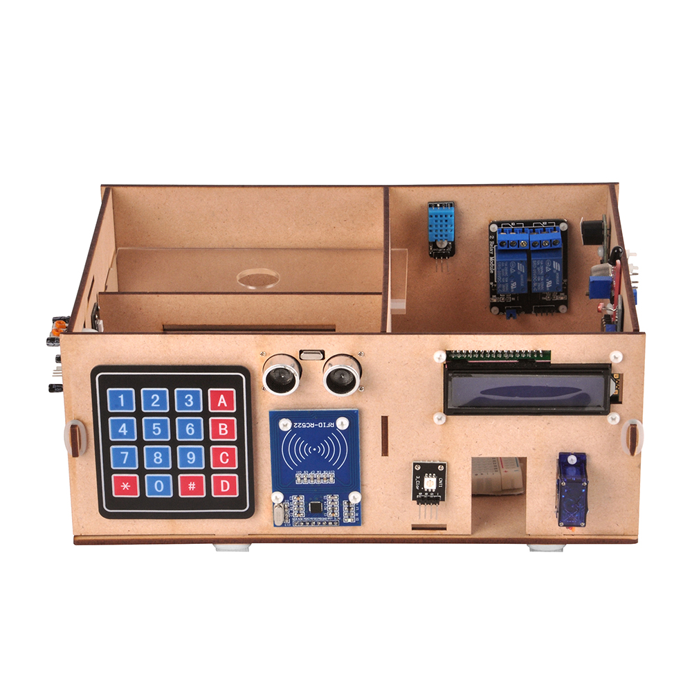
Please refer to Osoyoo Yun IoT Lesson 8 – Model Installation
Connection
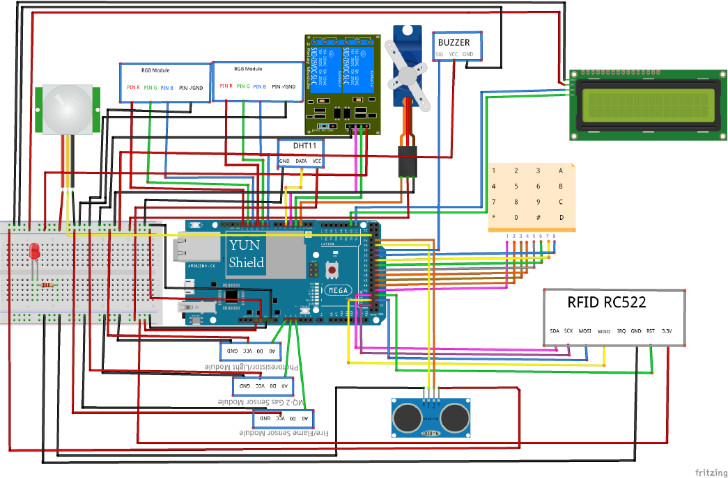
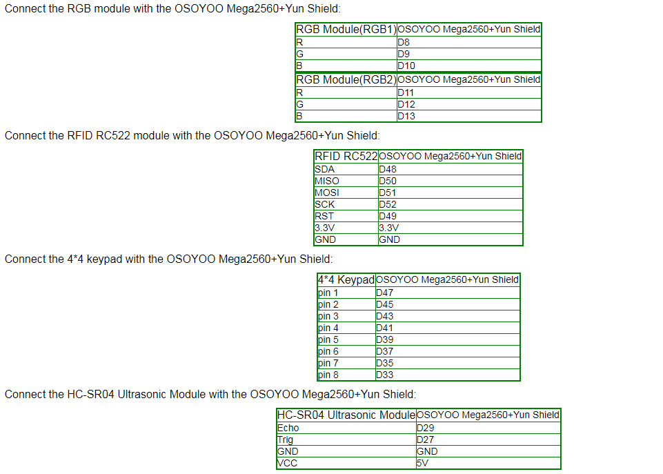
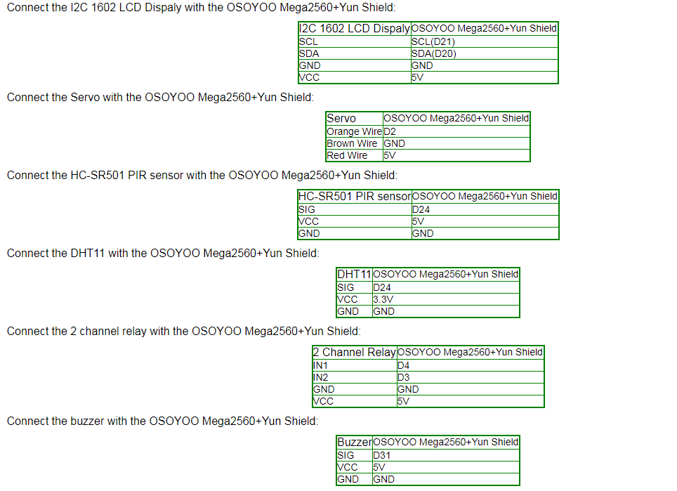
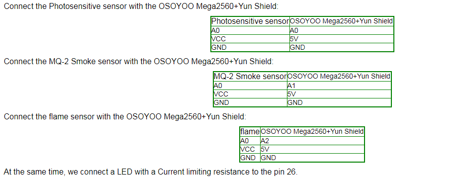
Note:
Before you start this tutorial, make sure you know how to use these devices, or you need to learn the previous tutorial. Because of the variety of sensors used in this tutorial, be careful, you can also use the code in the previous tutorial to detect whether the connection is correct.
Software
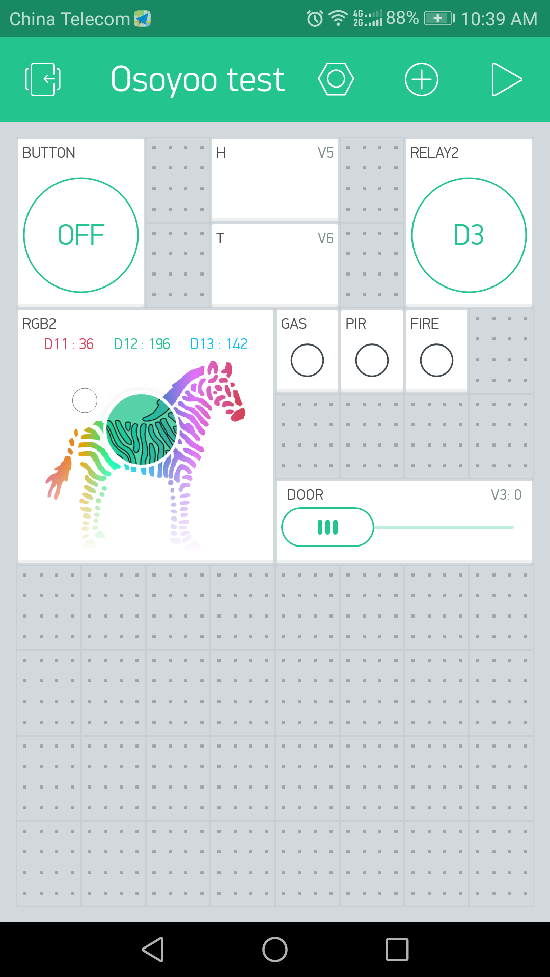
In this project, we need to add the Blynk widgets and their settings are as follows:
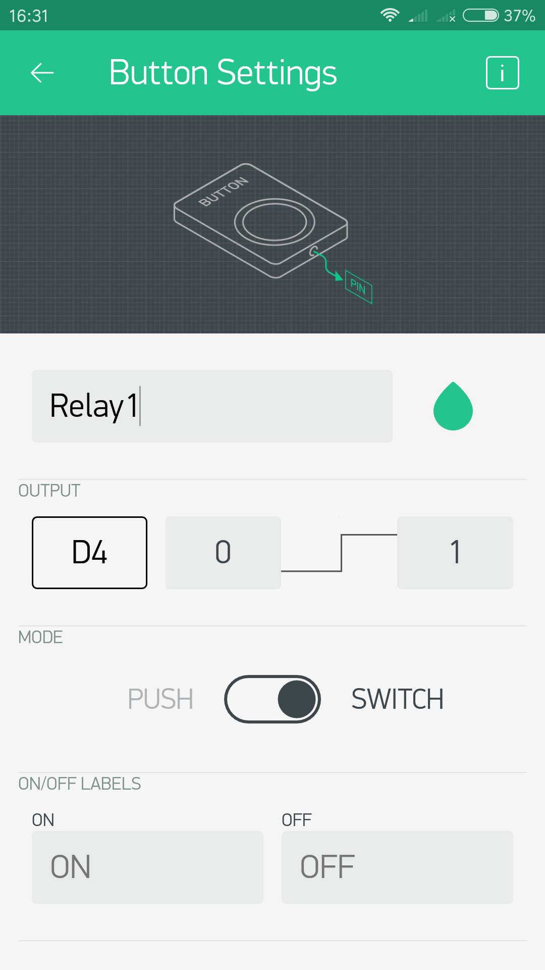
Button widgets to control the 2 channels relay:
We need to add 2 button widget here.
Button 1: Name: "Relay 1"; PIN:"D4"; OUTPUT:"0-1"; MODE: "SWITCH";
Button 2: Name: "Relay 2"; PIN:"D3"; OUTPUT:"0-1"; MODE: "SWITCH".
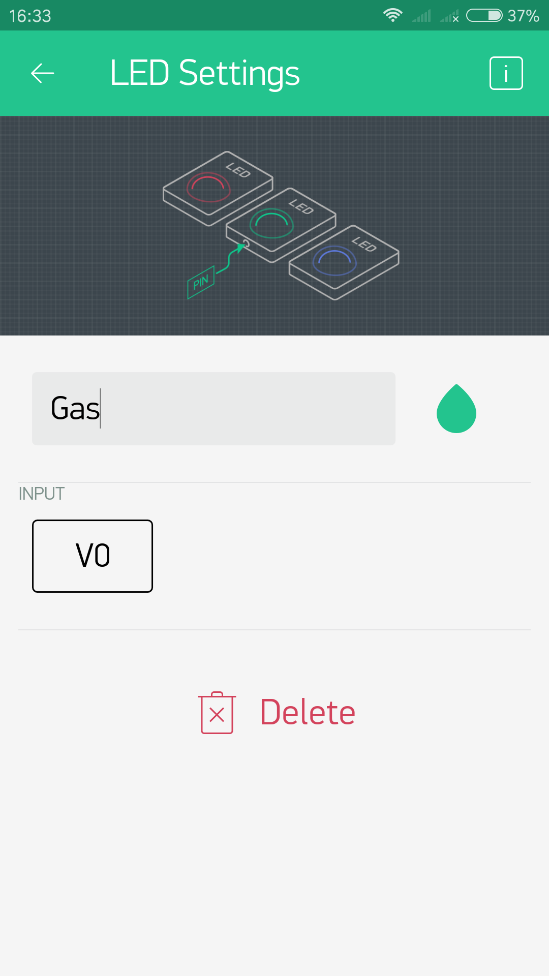
LED widgets to indicate the state of the sensors:
LED 1: Name: "Gas"; INPUT PIN:"V0";
LED 2: Name: "PIR"; INPUT PIN:"V1";
LED 3: Name: "FIRE"; INPUT PIN:"V2".
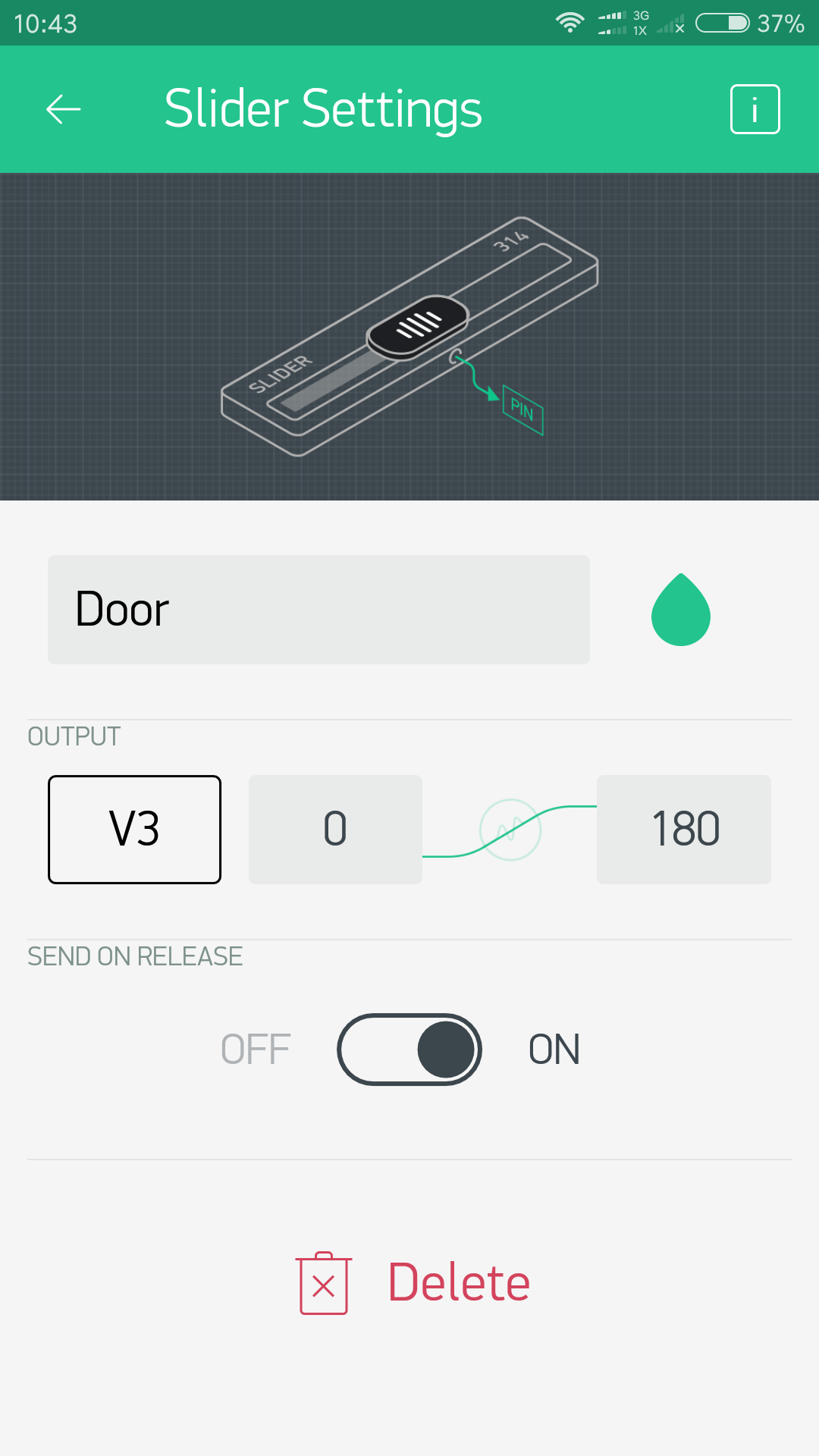
Slider widgets to control the servo:
Slider:
Name: "Door";
OUTPUT PIN:"V3";"0~180";
SEND ON RELEASE: "ON".
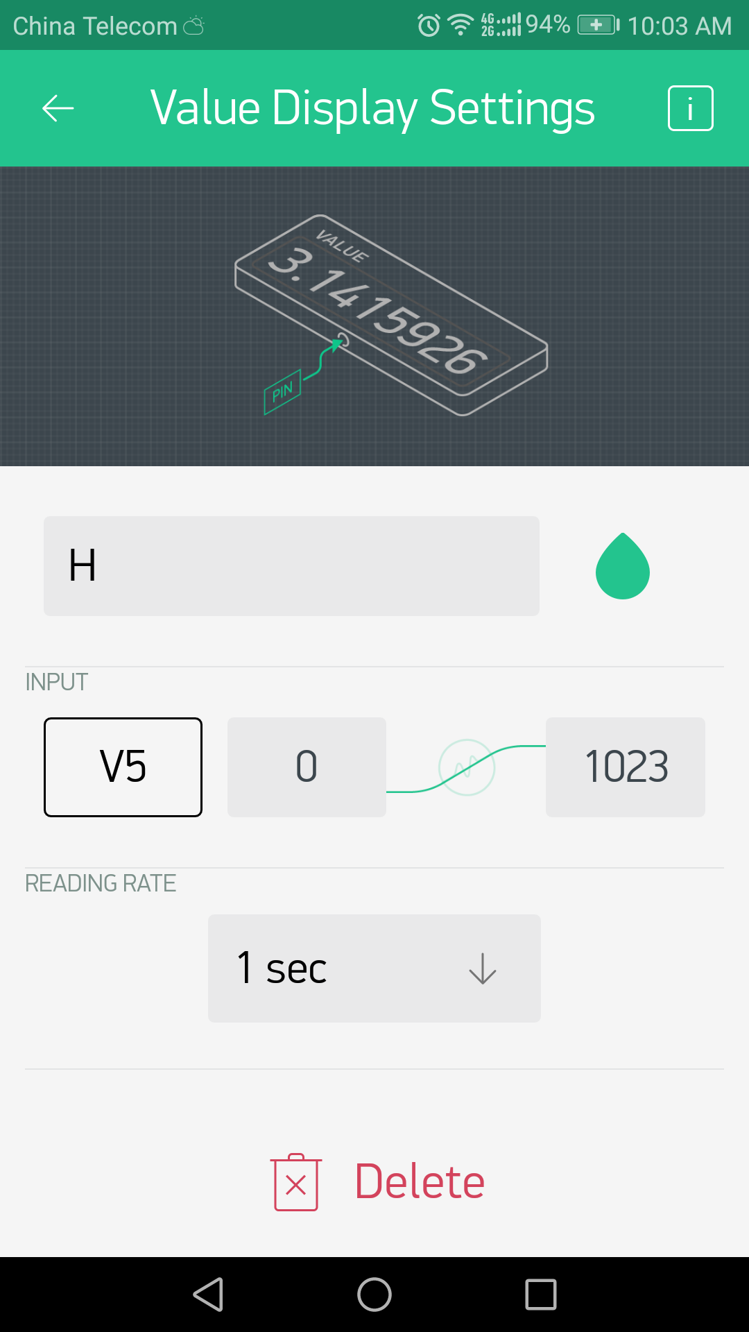
Value Display widgets to display the real-time humidity and temperature value:
Value Dispaly1:Name:"H", INPUTPIN:"V5";"0~1023";READING RATE:"1sec";
Value Dispaly1:Name:"T", INPUTPIN:"V6";"0~1023";READING RATE:"1sec".
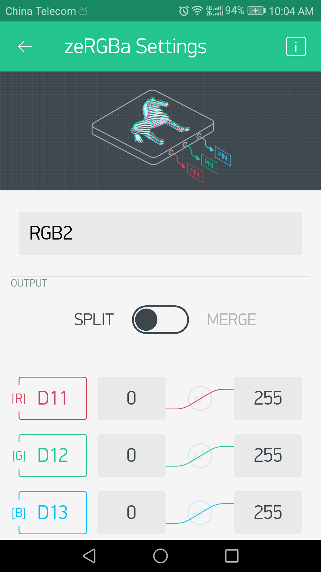
zeRGBa widget to control the RGB module:
zeRGBa:
Name:"RGB2";
OUTPUT:"SPLIT",
R PIN:"D11 0~255",
G PIN:"D12 0~255",
B PIN:"D13 0~255".
After completed above operations, open the Blynk app and you will see as the picture shows
Code Program
After above operations are completed, make sure that the Yun Shield is on the same network with the computer. Open the Arduino IDE and choose corresponding board type and port type for you project. Then load up the following sketch onto your Arduino.
You can get the Arduino sketch here.
In this example sketch, find this line:
char auth[] ="YourAuthToken";
This is the Auth Token that you emailed yourself. Please check your email and copy it, then paste it inside the quotation marks.
It should look similar to this:
char auth[] = "f45626c103a94983b469637978b0c78a";
Find below line and you can also change it, the password "123A456" is used to unlock the door by controlling the servo rotation.
char Master[Password_Length] = "123A456";
Upload the sketch to the board. Wait until you see something like this:
avrdude done. Thank you.
Congrats! You are all set! Now your hardware is connected to the Blynk Cloud!
Running Result
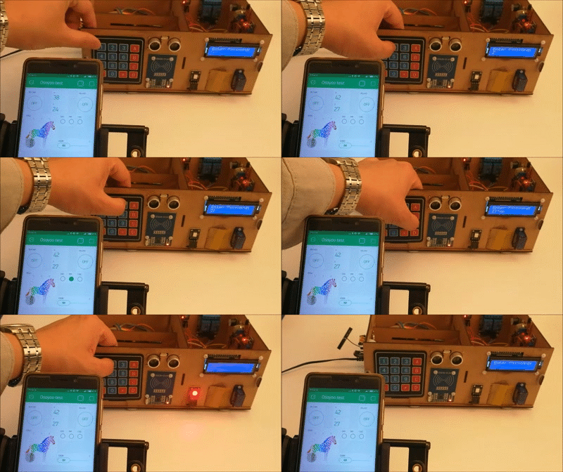
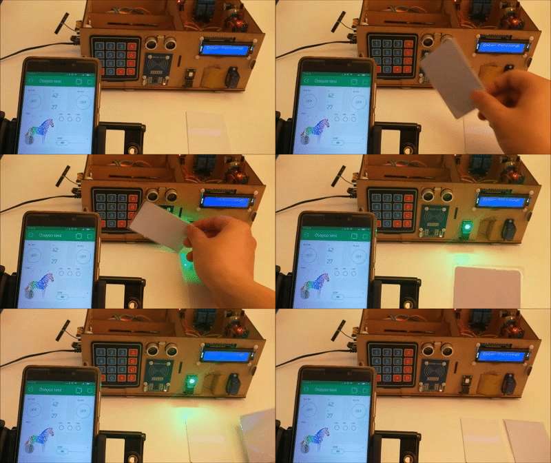
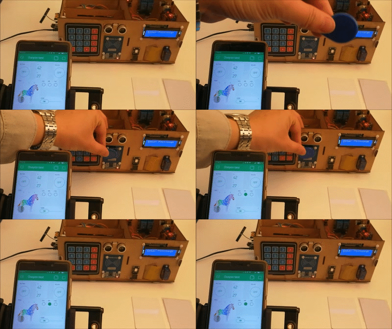
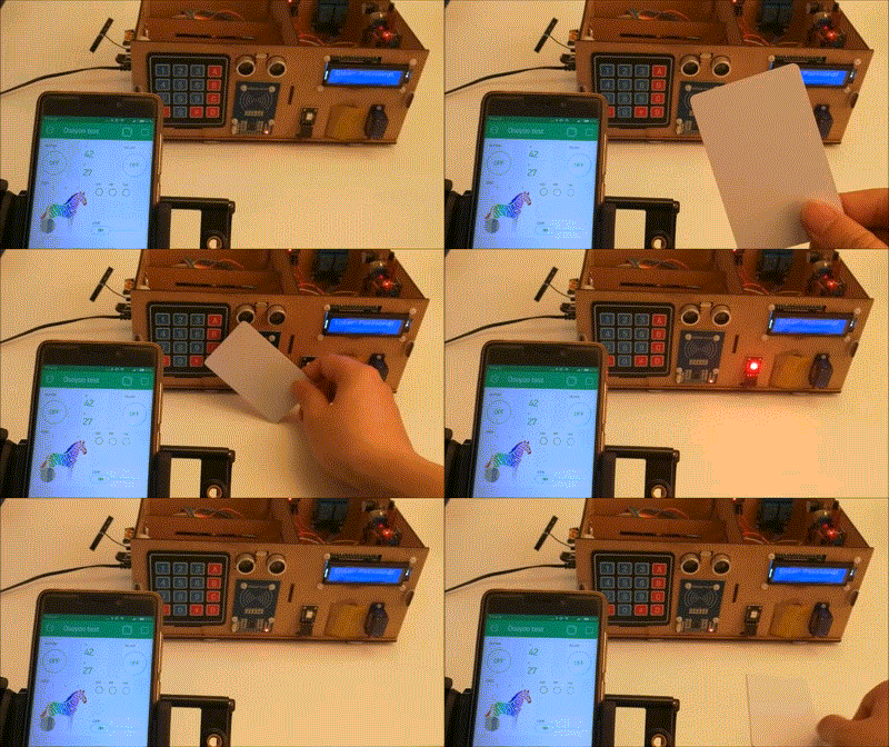
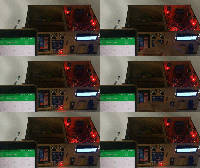
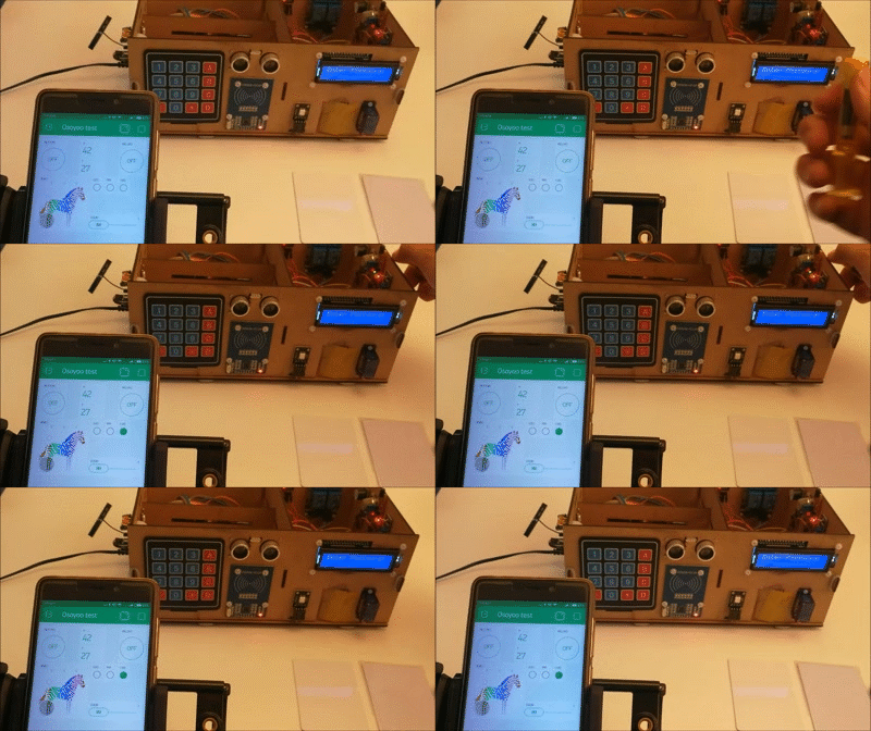
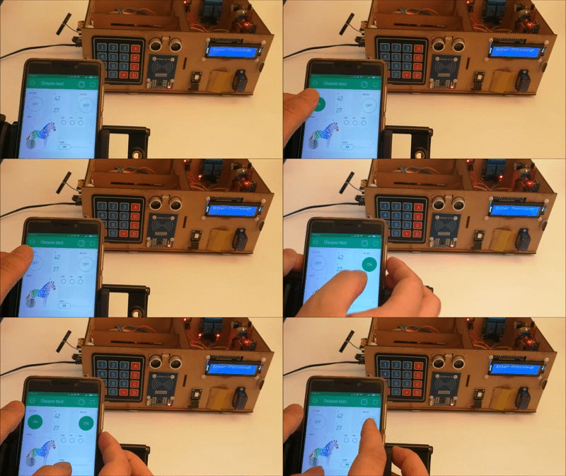
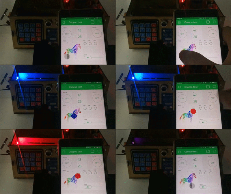
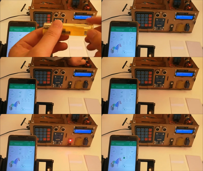
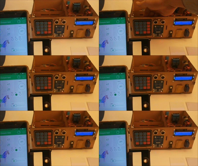
After you finished all above operations, open the Blynk APP, press the PLAY button. This will switch you from EDIT mode to PLAY mode where you can interact with the hardware. While in PLAY mode, you won’t be able to drag or set up new widgets, press STOP and get back to EDIT mode.
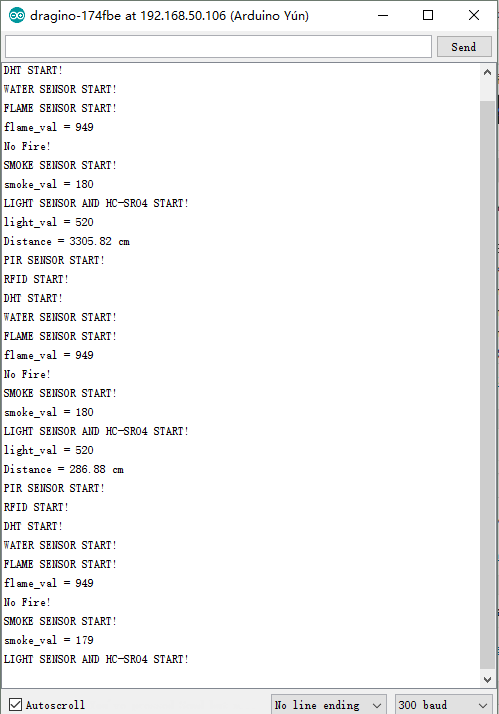
On the other hand, open the serial monitor, and you can see the running state of the entire smart home system as the picture shows:
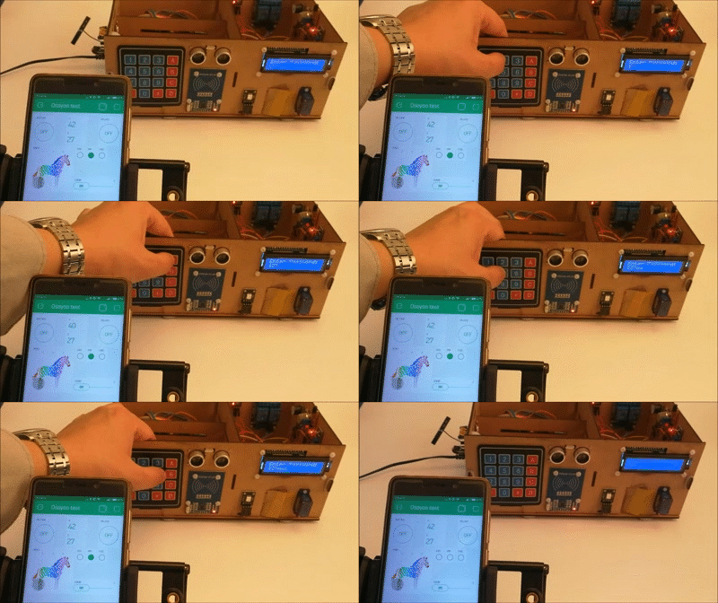
Now, you can open the door by using the keyboard or by swiping the card through the RFID module, it is also feasible to open the door through a mobile phone, you only need to slide the “Door” slider in the Blynk app.
Enter the correct password. The green light at the door will on and the door will be open.
Enter the wrong password. The red light at the door will be on and the door will not be open.
With the corresponding RFID card, you'll see it as the picture show. The green light on the door will on and the door will be open.
With the wrong RFID card, you'll see it asthe picture show. The red light at the door will be lit and the door will not be open.
When the flame is approaching, the red light will appear on the door, the buzzer will beep, and the LED widget representing the flame sensor on the phone app will become a bright state.
When the gas is near the MQ2 gas sensor, the system will also appear
When the ambient light is darkened and the object is near the ultrasonic sensor, the indoor LED will on.
When the hand is near the PIR sensor, the LED on the phone representing the sensor will remain bright.
We can easily use the smartphone app to control the relay.
Control RGB color through app..
More Detail
Please refer to:
http://osoyoo.com/?p=15678