Nodemcu GPS Tacker Using Blynk App
by hariramanil810 in Circuits > Sensors
73 Views, 1 Favorites, 0 Comments
Nodemcu GPS Tacker Using Blynk App
.png)
.png)
.png)
.png)
.png)
.png)
.png)
.png)
.png)
This is a nodemcu GPS Tracker for tracking simple devices from theft and other possible things can be fixed on a vehicle also with good internet facility by a dongle or some sort of network provider
Supplies
.png)
.png)
.png)
.png)
.png)
If you have hard-time 3d printing stuff and other materials which i have provided in this project please refer the professionals for the help, JLCPCB is one of the best company from shenzhen china they provide, PCB manufacturing, PCBA and 3D printing services to people in need, they provide good quality products in all sectors
Please use the following link to register an account in JLCPCB
Pcb Manufacturing
----------
2 layers
4 layers
6 layers
PCBA Services
JLCPCB have 350k+ Components In-stock. You don’t have to worry about parts sourcing, this helps you to save time and hassle, also keeps your costs down.
Moreover, you can pre-order parts and hold the inventory at JLCPCB, giving you peace-of-mind that you won't run into any last minute part shortages. jlcpcb.com/RNA
3d printing
-------------------
SLA -- MJF --SLM -- FDM -- & SLS. easy order and fast shipping makes JLCPCB better companion among other manufactures try out JLCPCB 3D Printing servies
JLCPCB 3D Printing starts at $1 &Get $54 Coupons for new users
A GPS tracker is a navigation device generally on a vehicle, asset, person, or animal that uses the Global Positioning System (GPS) to determine its movement and geographic position. GPS tracking devices send special satellite signals that are processed by a receiver. Locations are stored in the tracking unit or transmitted to an Internet-connected device using the cellular network or WiFi worldwide. GPS trackers connect to a series of satellites to determine location. The tracker uses a process called trilateration which uses the position of three or more satellites from the Global Navigation Satellite System (GNSS) network and their distance from them to determine latitude, longitude, elevation, and time.
In this project, we will use Quectel L86 GPS Module and interface it with NodeMCU ESP8266 Board. Instead of Quectel L86 GPS Module, you can also use Neo-6M GPS Module or any other similar GPS Module. Using the TinyGPS library, we will determine the latitude, longitude, speed, bearing as well as the location on Map. We will send all these parameters to the Blynk Application and monitor the real-time data along with the map on Blynk Dashboard.
Making
.png)
.png)
.png)
.png)
.png)
.png)
.png)
.png)
The L86 is an ideal solution for wearable fitness devices due to its ultra-compact design and low power demands. Its Low Power feature enables GPS connectivity at around half the power consumption of normal mode while in static receiving mode. Combined with its precision and high sensitivity, this makes the L86 suitable also for a broad range of IoT applications such as portable devices, automotive, personal tracking, security, and industrial PDAs.

The L86 has a patch antenna on top measuring 16.0mm × 16.0mm × 6.45mm, with 66 acquisition channels and 22 tracking channels. It acquires and tracks satellites in the shortest time even at the indoor signal level. The module operates at 2.8V~4.3V with a typical power consumption of 20mA and in Standby mode power consumption is around 1.0mA. To learn more about the L86 GPS module, you can check the L86 Datasheet.
The Quectel L86/L80 GPS Module has 12 pins as shown in the image below.

The L86 is a tiny SMD-type Module that doesn’t have any male/female header pins for testing. So you can use the male header pin with 2.54 spacing and solder them on the L86 PCB from the bottom.

Once, you solder all the 12 Pins on the L86 Module, the Module becomes breadboard friendly. You can now insert the module on the breadboard easily.

Circuit for GPS Tracker using ESP8266
Now let us move to the project part & make Real Time GPS Tracker using ESP8266 & Blynk. The connection diagram is fairly simple.
![]()
Connect the VCC/GND of the L86 GPS Module to 3.3V/GND of NodeMCU ESP8266. Do not supply more than 3.3V. Similarly, connect the VCC backup (V_BCKP) with VCC or to an external battery. It won’t work if this pin is not powered.
Connect the RX/TX of L86 to the D1/D2 of the NodeMCU. This is for Serial Communication using Software Serial.
![]()
You can use a jumper wire to connect directly or use a breadboard to assemble the circuit. Hence the hardware for GPS Tracker using ESP8266 is ready.
Setting Up Blynk App
Step 1:

Sign in to Blynk app and create a new project.
Step 2:
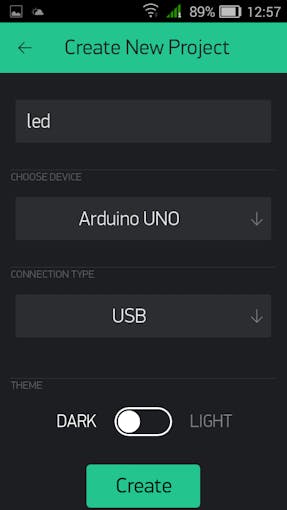
Give a name to your project. Choose device as Arduino UNO. Select Connection type as USB.
Step 3:

Check your E-mail for Author Token.
Step 4:


Select "ADD DEVICE" and add Button. Click on button you added. There opens Button Manager. In output select Digital 13th pin.
Step 5:

In Code copy and paste your Author Token.
Step 6:

Open Command Prompt. Write
cd "Your Blynk Scripts address"
then press enter.
Step 7:

Now write blynk-ser.bat -c COM3 or any com your device is connected. Press enter. Now you can control your device with Blynk.
Code
What is ESP8266 and how does it work?
ESP8266 is a low-cost WiFi module that belongs to ESP's family which you can use it to control your electronics projects anywhere in the world. It has an in-built microcontroller and a 1MB flash allowing it to connect to a WiFi. The TCP/IP protocol stack allows the module to communicate with WiFi signals. The maximum working voltage of the module is 3.3v so you cant supply 5v as it will fry the module.
Let's take an example of controlling an LED light using ESP8266 by smartphone. The ESP8266 acts as an interpreter between the LED and the smartphone. Since we are using the Blynk app to control the LED further explanations will be based on it.
Then scroll down until you see the heading "auth token."

Auth token is an authentication code that I have said before. It is to create a secure connection from Blynk app to the ESP8266 by the web server and also to identify the device while it is to be communicated.
Now choose any methods under auth tokens to save the auth code. The auth code should be entered in the program code later.
Setting up the Arduino IDE for programming ESP8266
Before programming the ESP8266 in Arduino IDE you have to change the board manager to ESP8266.
If you haven't made any projects on ESP8266 before, you have to follow these steps on the website (given below link) to install ESP8266 board manager on Arduino IDE.
https://randomnerdtutorials.com/how-to-install-esp8266-board-arduino-ide/
If you had finished installing the board manager or already had installed it then choose the board manager type as "Generic ESP8266 Module."

To communicate your ESP8266 with the Blynk app, you have to add a Blynk library to your arduino IDE folder. For that, you need to download the library file from the link below:
https://github.com/blynkkk/blynk-library/releases
Once you have downloaded it, extract the file and copy the folders. Then open your Arduino folder and click on libraries folder. Right click and click on paste button. You have successfully installed the Blynk libraries.
Files & Schematics
.png)