NodeMCU Alexa TV Control
by AndersSeverinsen in Circuits > Arduino
3752 Views, 15 Favorites, 0 Comments
NodeMCU Alexa TV Control
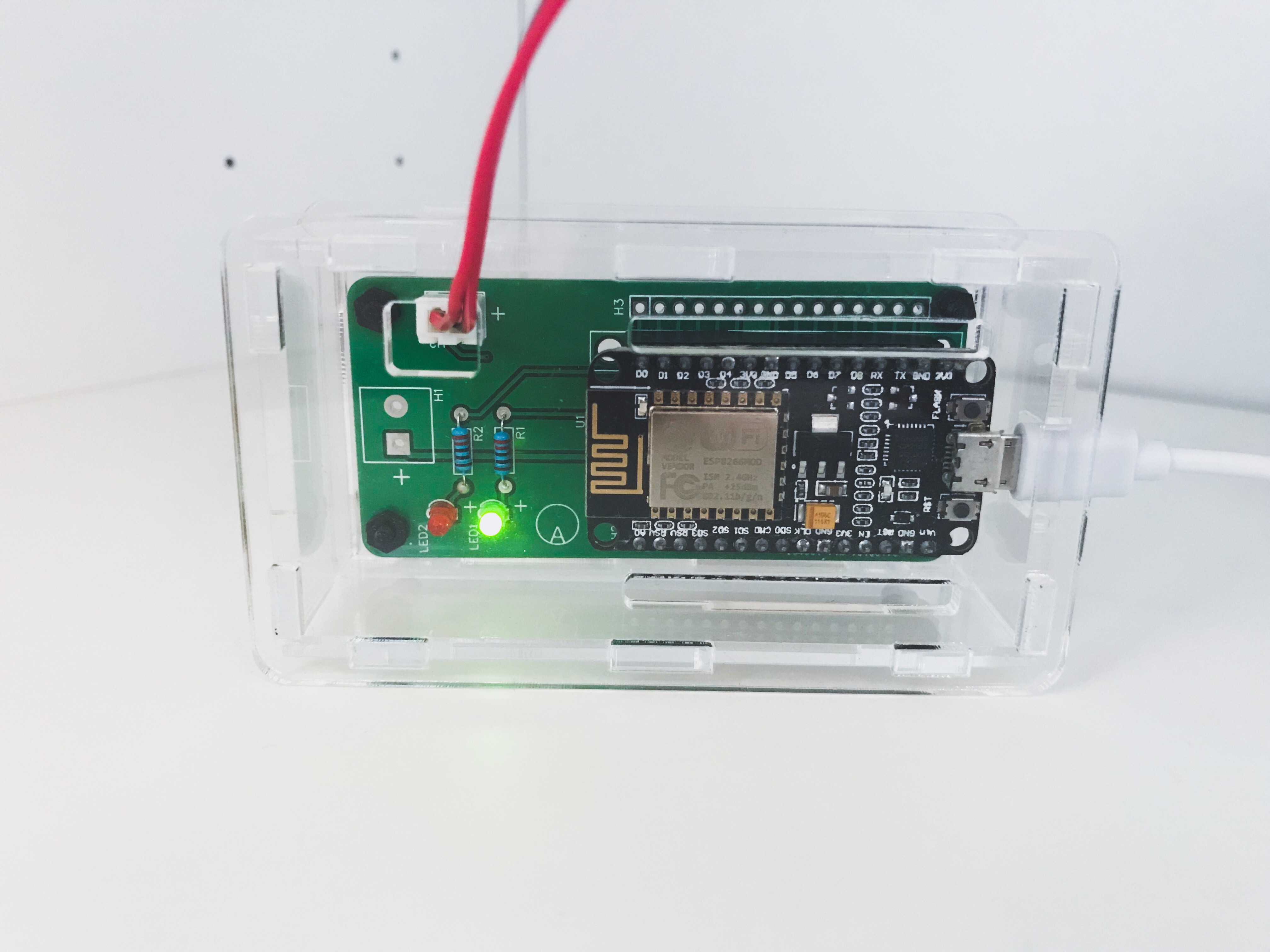
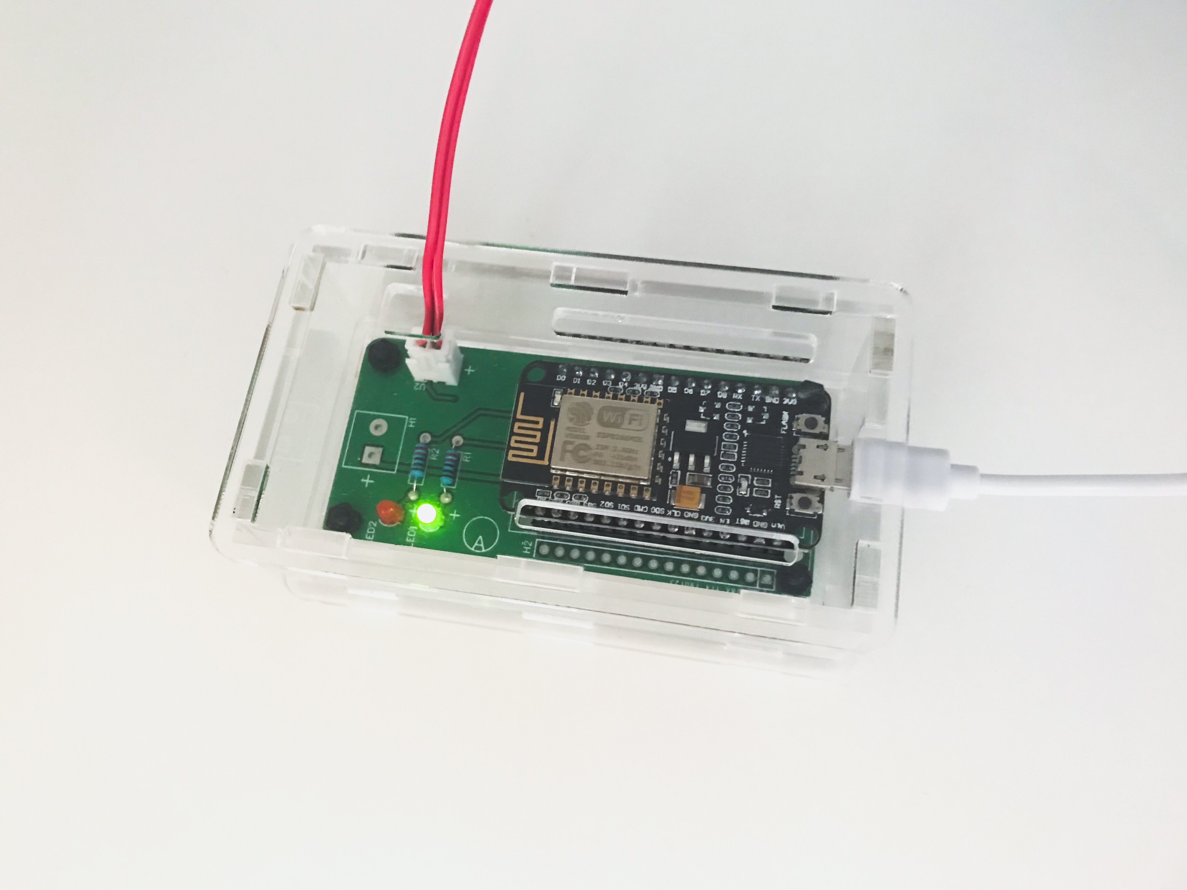
Learn how to make Alexa control you TV, with a NodeMCU.
If you like this project, feel free to vote for it in the Sensors Contest.
Supplies
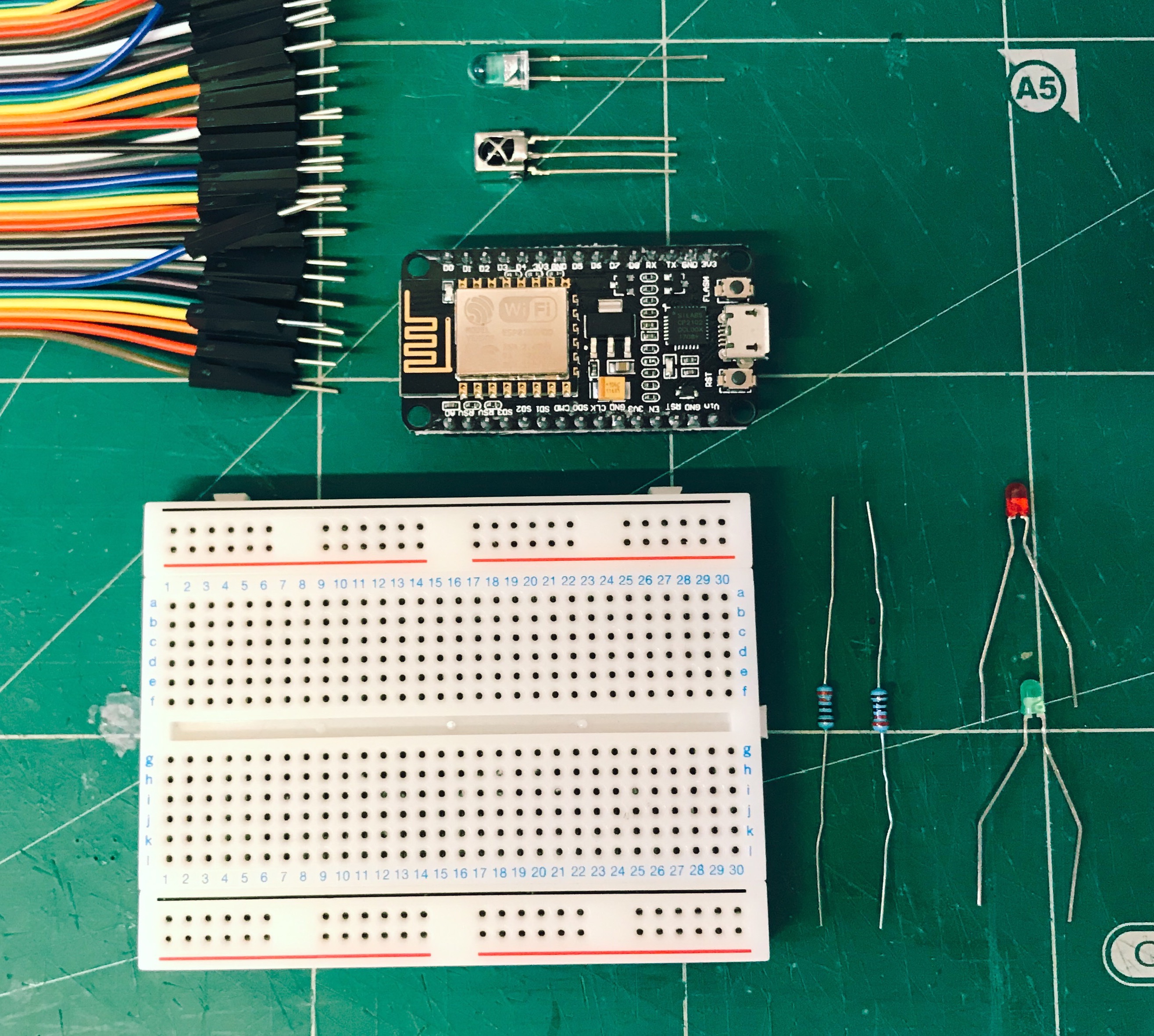
Components:
A NodeMCU Esp8266 and a Micro USB Cable with data lines
An Arduino Uno for reading the IR signals
Two 3mm LEDs (I chose a red and a green)
Two 220 Ω Resistors
A Breadboard and Jumper Cables
Optional: A Custom PCB, a Laser Cut Case, Standoffs, JST Connectors, Wire and Single Row Female Header Pins
Tools:
A Computer
Optional: A Soldering Iron, a Wire Cutter and a PCB Holder
Setting Up Sinric
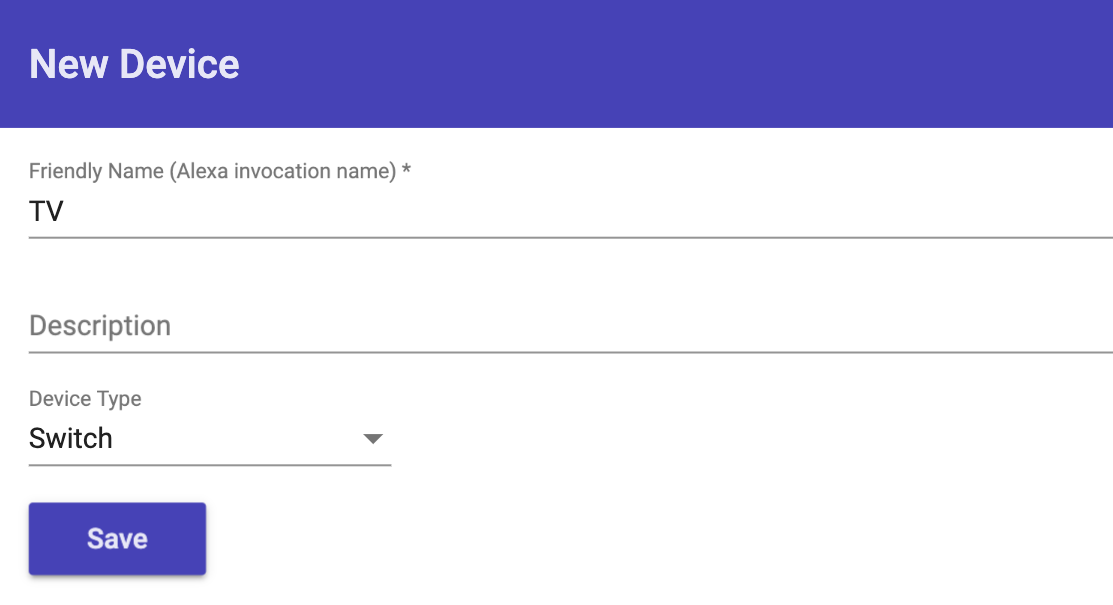
Sinric by Kakopappa
1. Go to Sinric.com and register for an account.
2. Login and COPY your API Key.
3. Create a new Smart Home Device by pressing Add, and typing in a name, and selecting Switch under Device Type. Then press Save.
4. Now you should see a new device on the dashboard. Copy the Device ID.
Setting Up the Arduino IDE
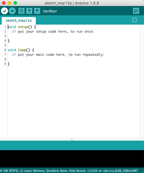
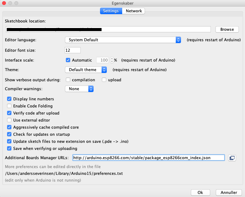
1. Download and install the Arduino IDE if you haven't already, by going to https://www.arduino.cc/en/Main/Software.
2. Open the Arduino IDE, and go into Preferences. Then under Additional Board Manager URLs, add this URL:
http://arduino.esp8266.com/stable/package_esp8266com_index.json
3. Download the ArduinoJson-v5.13.2.zip file
4. In the Arduino IDE, go to Sketch → Include Library → Add Zip Library and select the .zip file.
5. Repeat the process with the arduinoWebSockets-2.1.1.zip file:
6. Now go into Sketch → Include Library → Manage Libraries, and search for IRremoteESP8266. Select Version 2.5.3, and install.
7. Also install the IRremote library, the same way (latest version).
8. Then Exit and restart the IDE.
Reading the IR Signals From the TV Remote
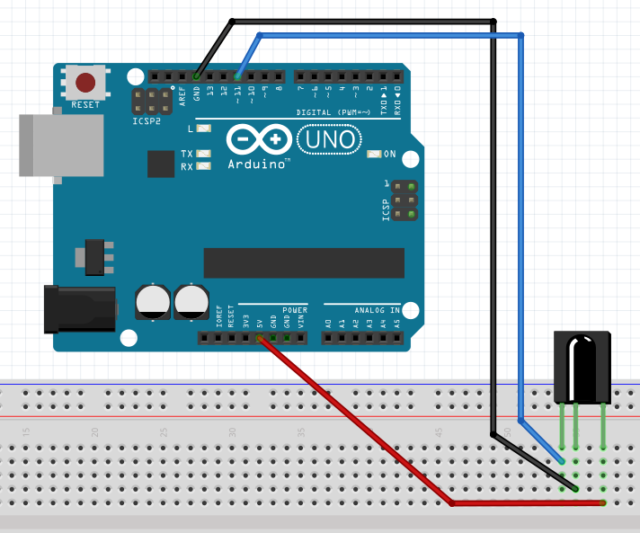
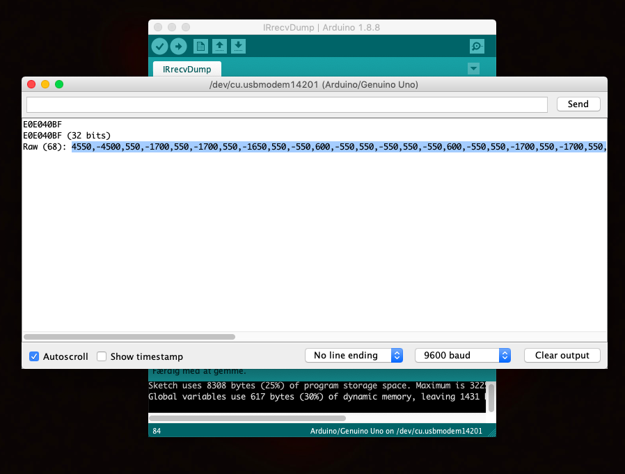
1. Start by connecting an IR Receiver to the Arduino Uno on a breadboard with Jumper Cables, as shown in the schematic.
2. Download the IRrecvDump_final.zip, unzip it, and open the .ino file in the Arduino IDE.
3. Plug the Arduino Uno into your computer.
4. In the Arduino IDE, under Tools and Board select Arduino/Genuino Uno, and under Port, select the correct port.
5. Upload the code to the Arduino, by pressing the arrow (→).
6. Open the Serial Monitor by going to Tools and Serial Monitor.
7. Set the baud rate to 9600.
8. Point you TV Remote at the IR Receiver and press the buttons you want to be able to control, and copy the Raw input for later.
9. When you are done noting the signals, disconnect the Arduino from your computer, ready for the next step.
Downloads
Setting Up the NodeMCU
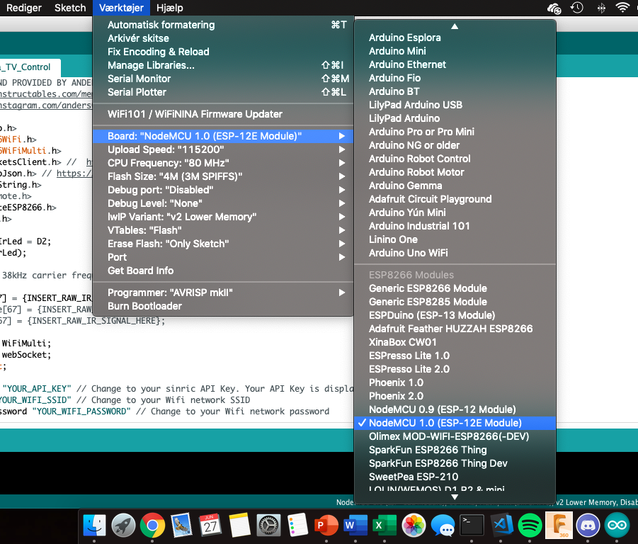
1. Download the Sinric_NodeMCU_Alexa_TV_Control.zip, unzip it, and open the .ino file in the Arduino IDE.
2. In the Arduino IDE, under Tools and Board select NodeMCU 1.0 (ESP-12E Module), under Flash Size select 4M (3M SPIFFS), and under Port select the correct port.
3. In Sinric_NodeMCU_Alexa_TV_Control.ino enter in your IR Remote Signals, Device ID, Api Key, Wifi Name and Wifi Password, in the specified places. To increase the number of devices, uncomment the specified lines of code.
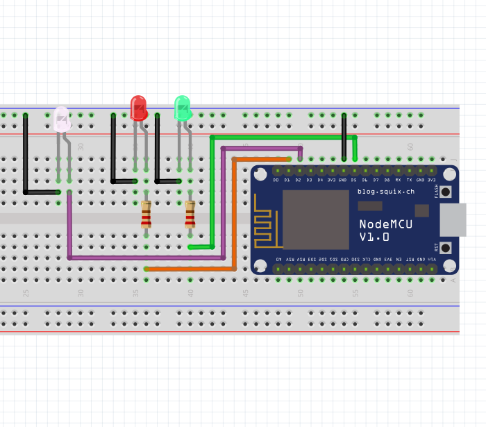
4. Connect up the NodeMCU to the IR LED, the Red and Green LEDs and the Resistors, on the Breadboard, as shown in the electronics diagram. (The red and green LEDs are not required but nice to have)
5. Connect the NodeMCU to your computer with a Micro USB cable.
6. Upload the code to the board.
7. The Green LED should light up, whenever it has connected to the Wifi.
Downloads
Setting It Up With Alexa

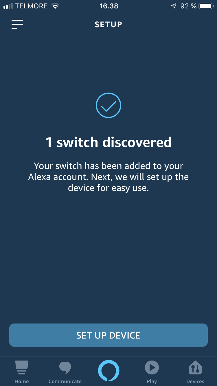
1. Install the Amazon Alexa App on your phone, and login with your Amazon account.
2. Go to Skills & Games, and search for sinric, select and press Enable, and you will be asked to login to your Sinric account.
3. Discover your device by going to Devices → + → Add Device → Other → DISCOVER DEVICES. (Make sure your Alexa is connected to the same network as the NodeMCU.)
4. Hopefully it should have discovered your device, so all you need to do is set up your device.
5. Now test it by placing the breadboard near the TV, pointing the IR LED at the TV, and saying something like: Alexa, turn on the TV. You should see the red LED blink and your TV turn on.
Optional: Custom PCB and Laser Cut Case
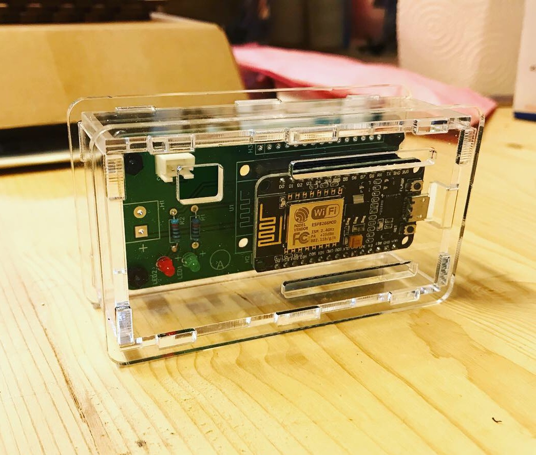
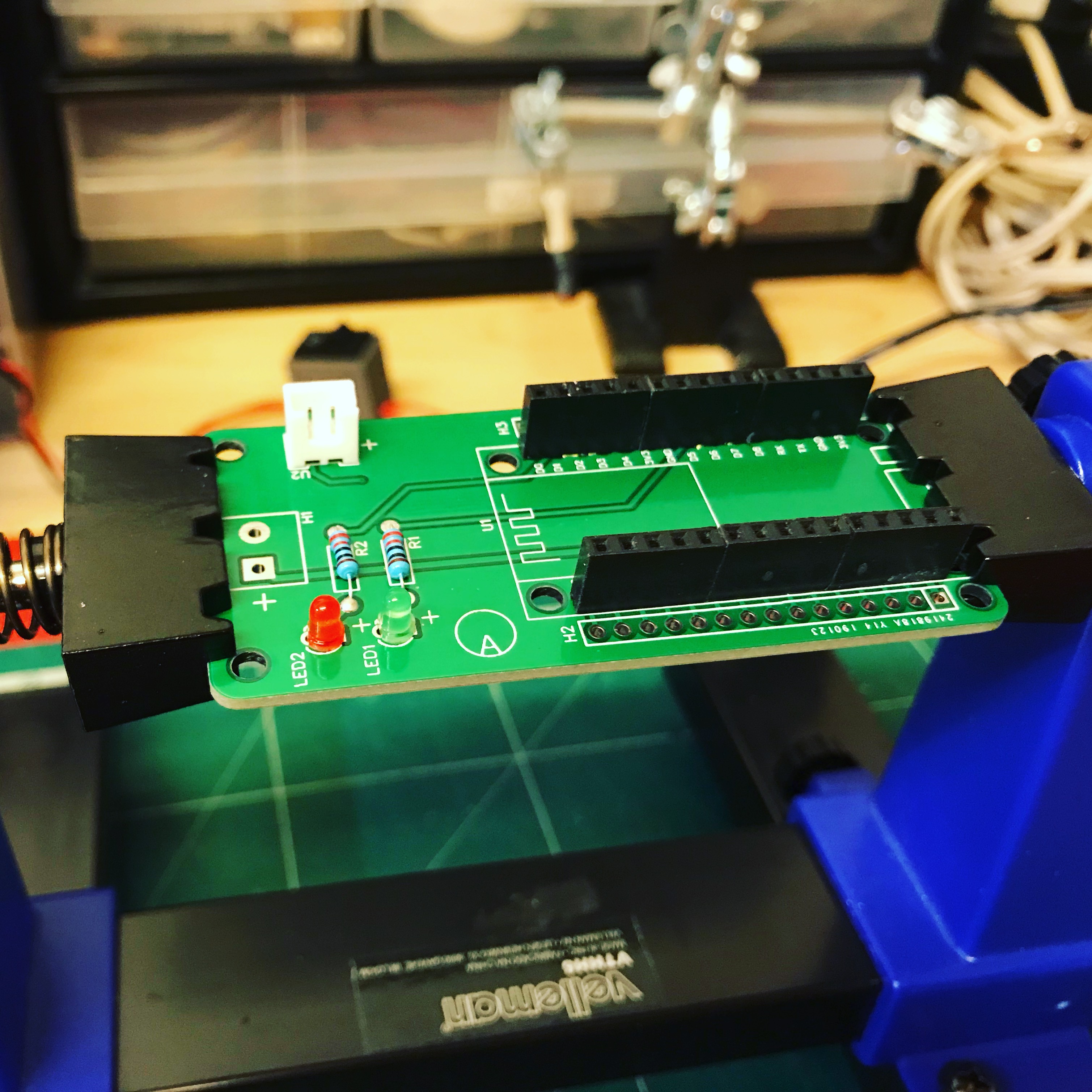
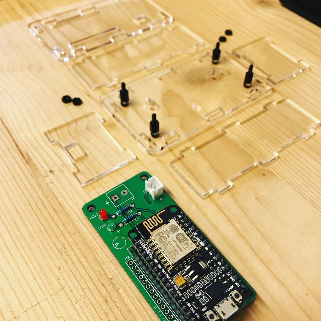
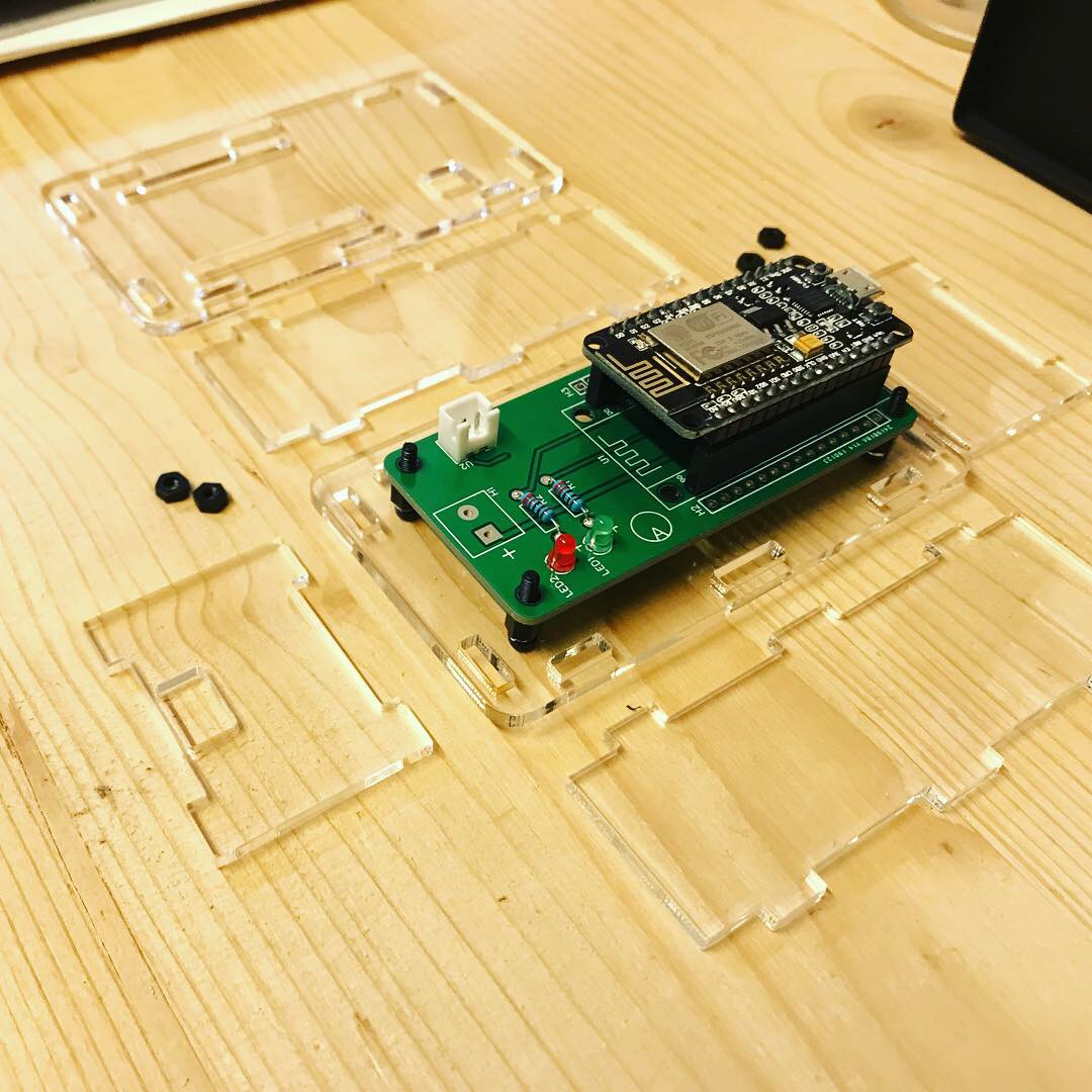
To make it look more professional and to make it more permanent, I made a custom PCB, to replace the breadboard.
I made the PCB with EasyEDA (unfortunately not Eagle because I'm not a pro at making PCBs), and ordered the PCB from JLCPCB, and the board worked first time. The IR LED can be connected to the JST connector, so the case can sit in a shelf under the TV, while the IR LED is mounted under the TV's IR Receiver.
I then made a Laser Cut case, to house the PCB, out of clear acrylic.