Nanoleaf Lamp
Hello! I'm Poornima Godavarthy and I've created a version of the Nanoleaf Lamp. This was made as part of my Principles of Engineering Class with Ms. Berbawy at Berbawy Makers.
This is a fun project that helped me improve my skillset with many of the machines in the Berbawy Makers Makerspace. I've learned to use a laser cutter and 3D printers while gaining familiarity with soldering. I've also gained an understanding of how to use an ESP 32 microcontroller in combination with Arduino programming to control the LEDs.
Special thanks to Hansi from Nerdforge for the project inspiration.
Supplies
- ESP32 (DOIT ESP 3 DEVKIT V1)
- Individually addressable LED strips
- breadboards
- P95 Acrylic
- 3D printer and filament
- Spray Paint (optional)
- Soldering Kit
CAD
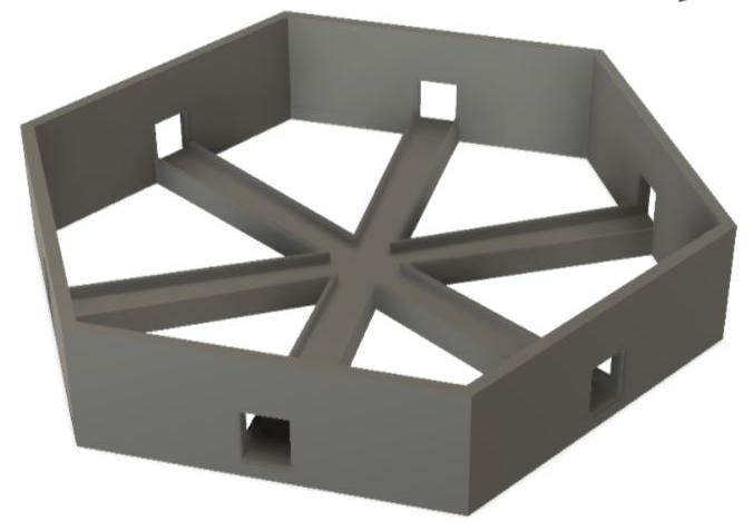
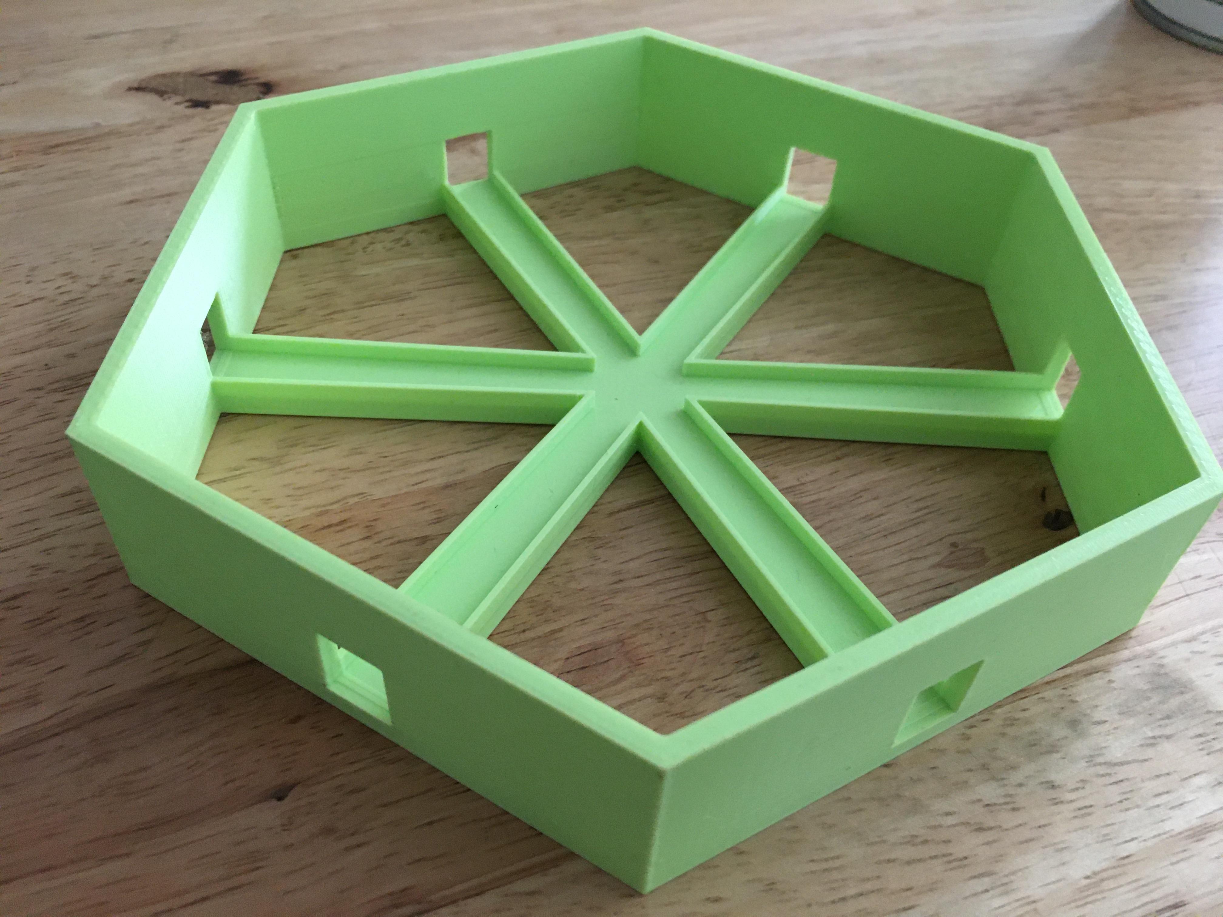
For the hexagon bases, I decided to CAD my own design in Autodesk Fusion 360.
I made sure to leave space on the bottom of the design in case I wanted to access the wires later on. I also included holes on each side to accommodate the connectors between each LED strip.
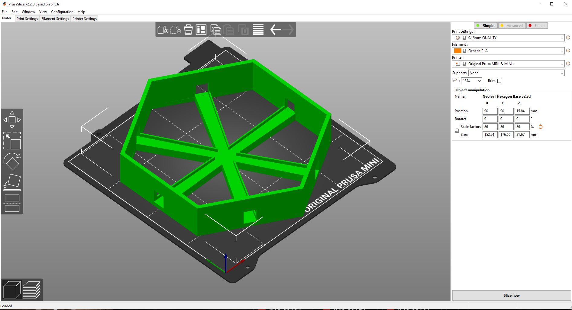
If you want the exact design, the STL file is linked here, otherwise, feel free to get creative to make your own design with customized dimensions. To slice the file, I used Prusa Slicer. The settings are listed in the linked image.
3D Printing
.JPG)
.jpg)
.jpg)
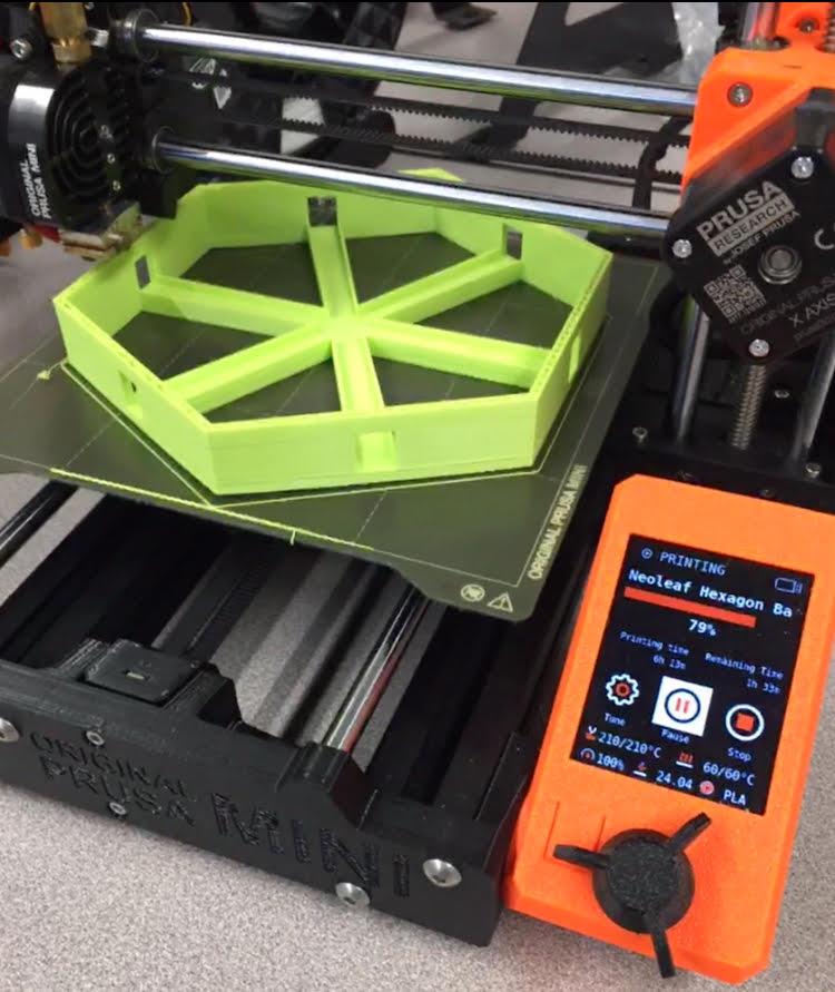
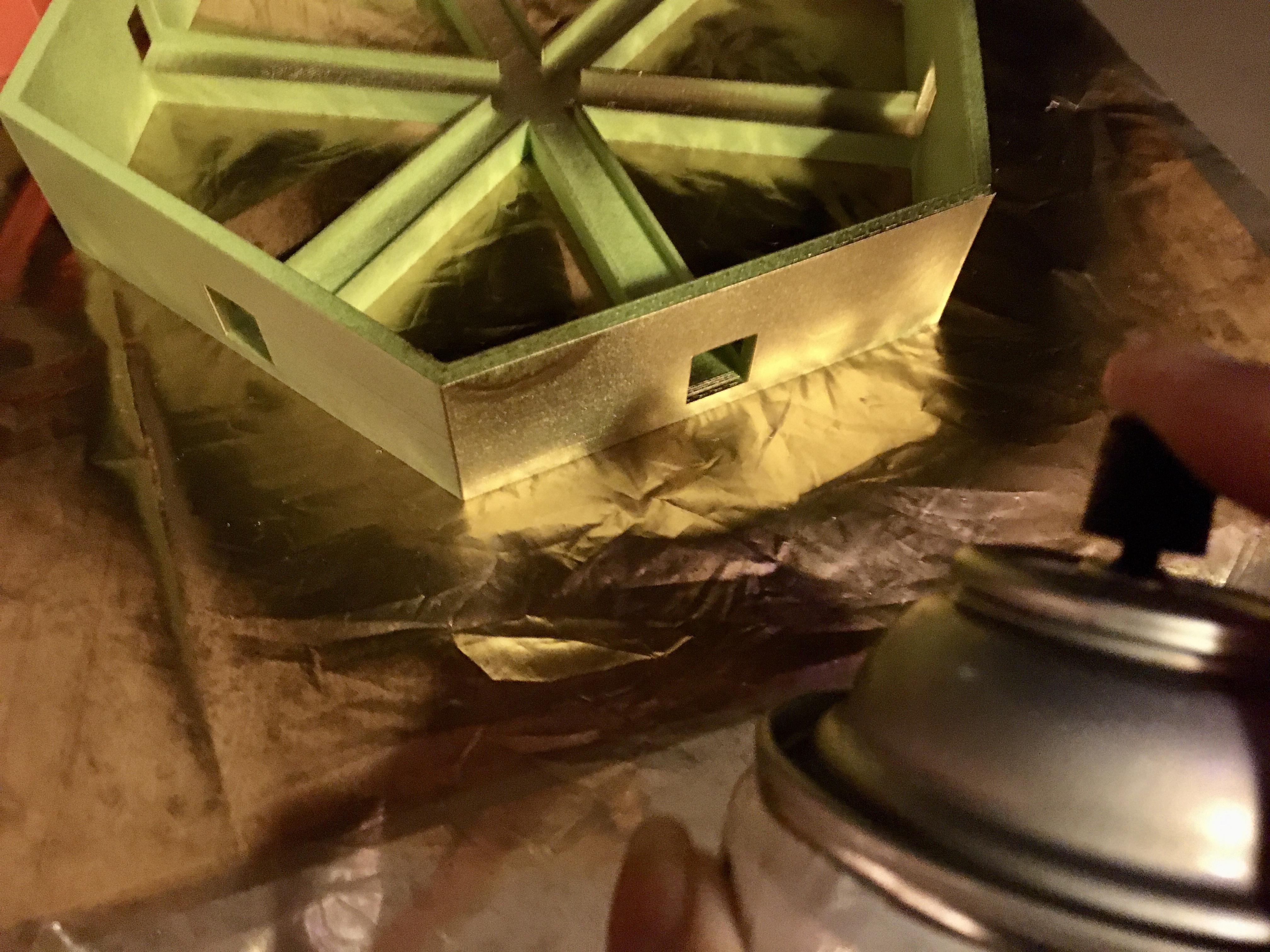
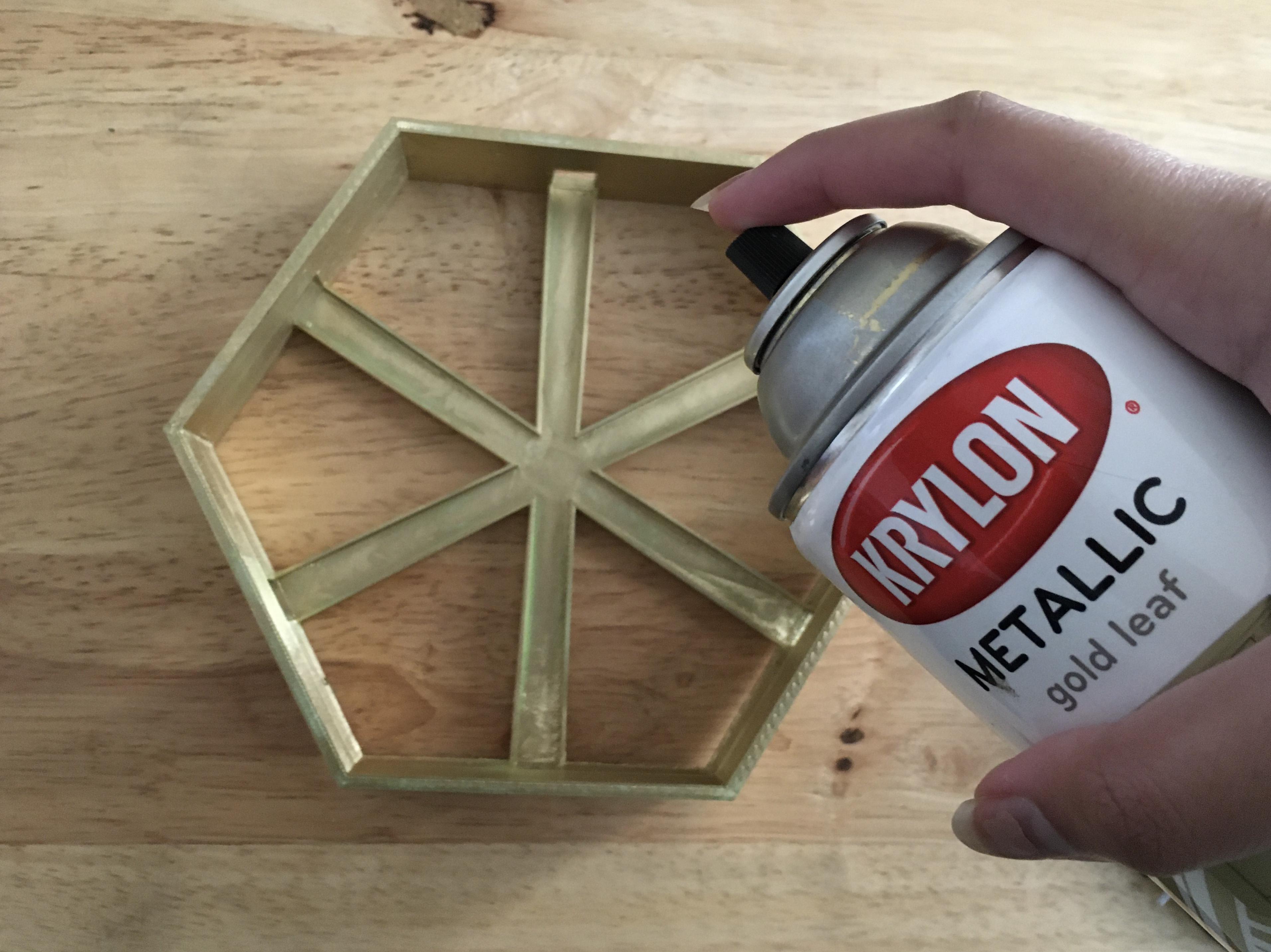
I used several Prusa Minis to print my hexagons and chose to spray paint them gold for an extra finishing touch.
Soldering LED Strips
.jpg)
.jpg)
.jpg)
.jpg)
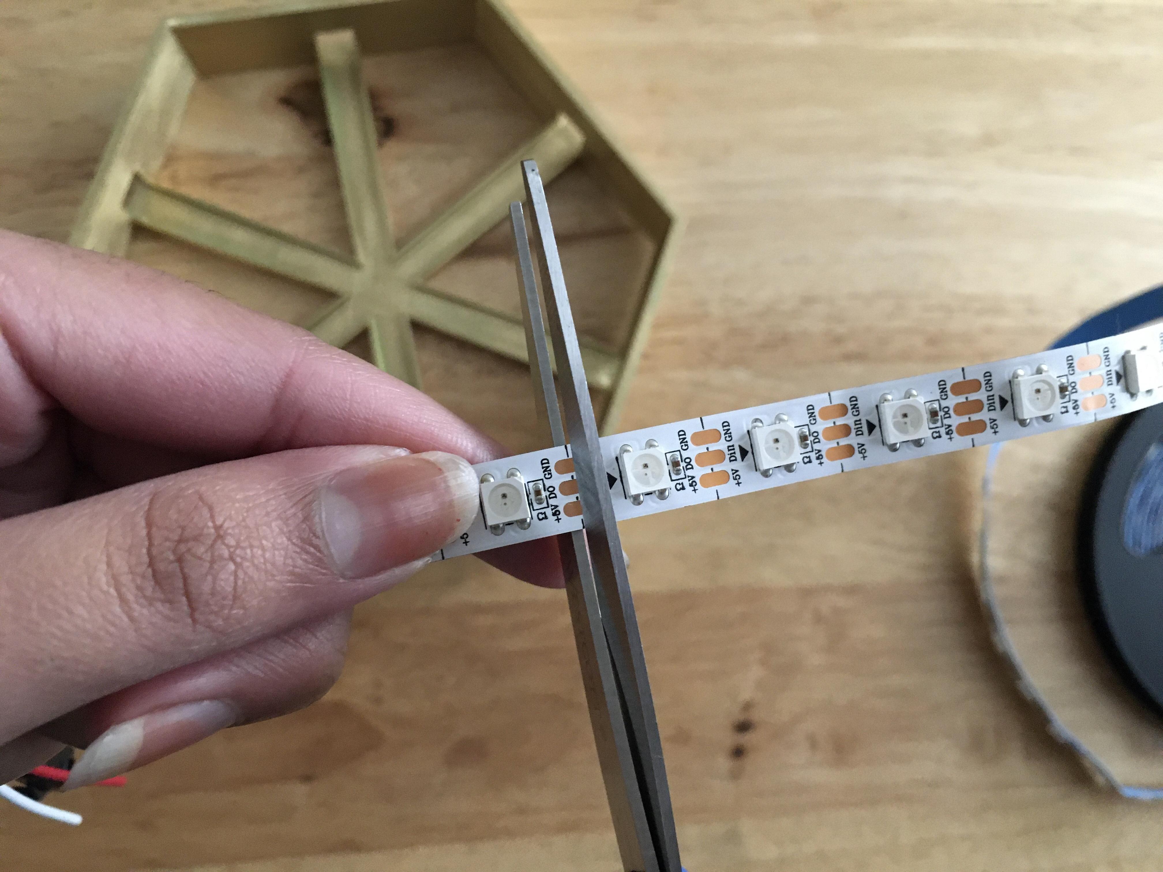
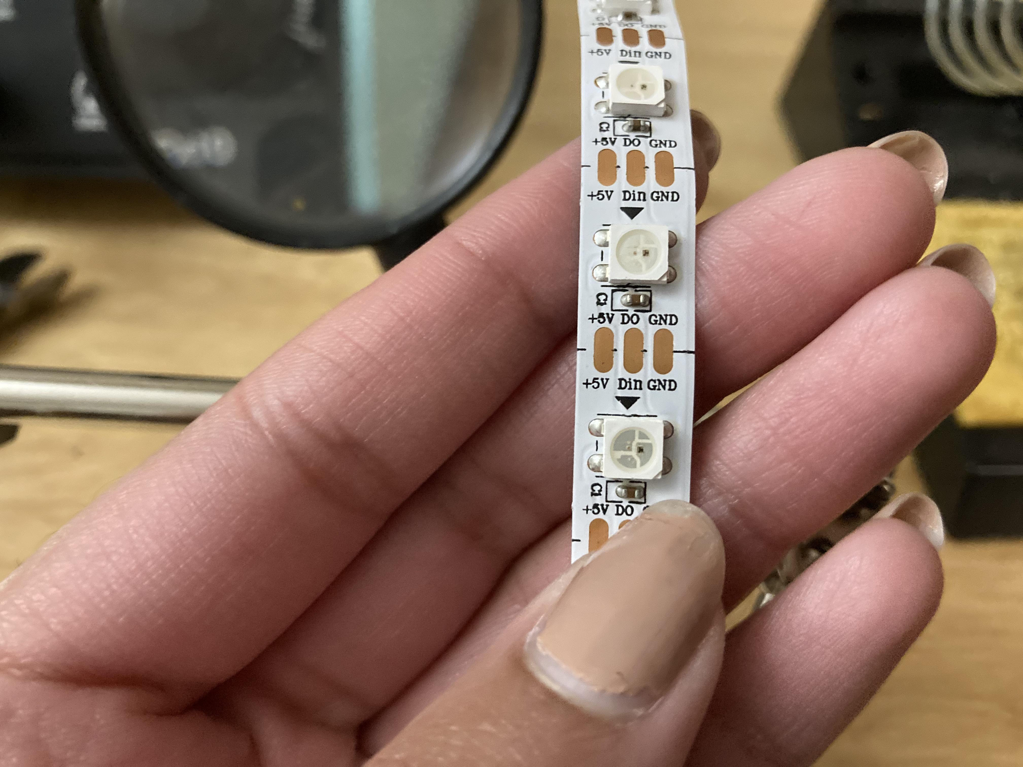
- First, measure out how many LED strips can fit in one of your bases. The one used in this tutorial has 27 per hexagon
- Then, cut the strips halfway between the copper joints to solder later
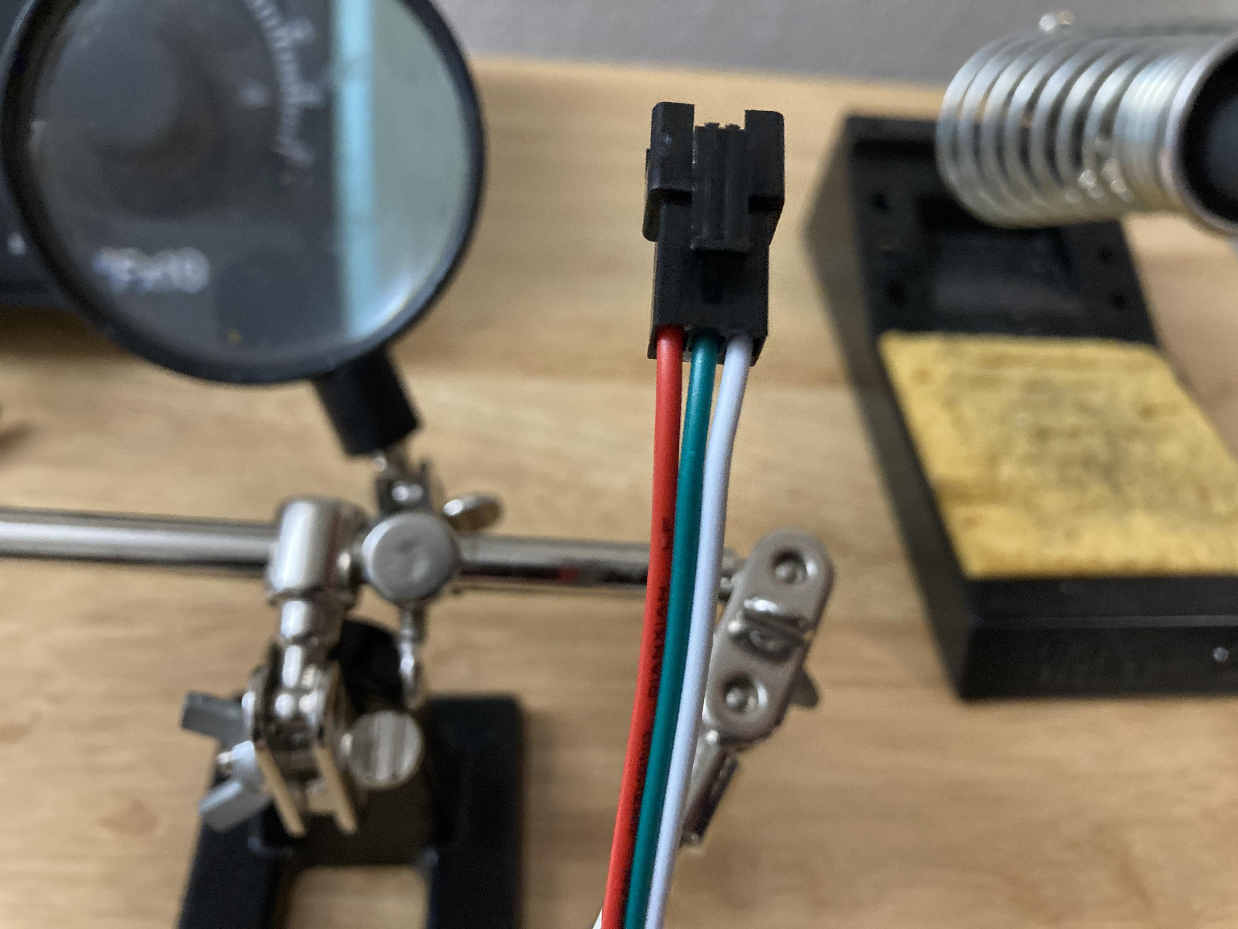
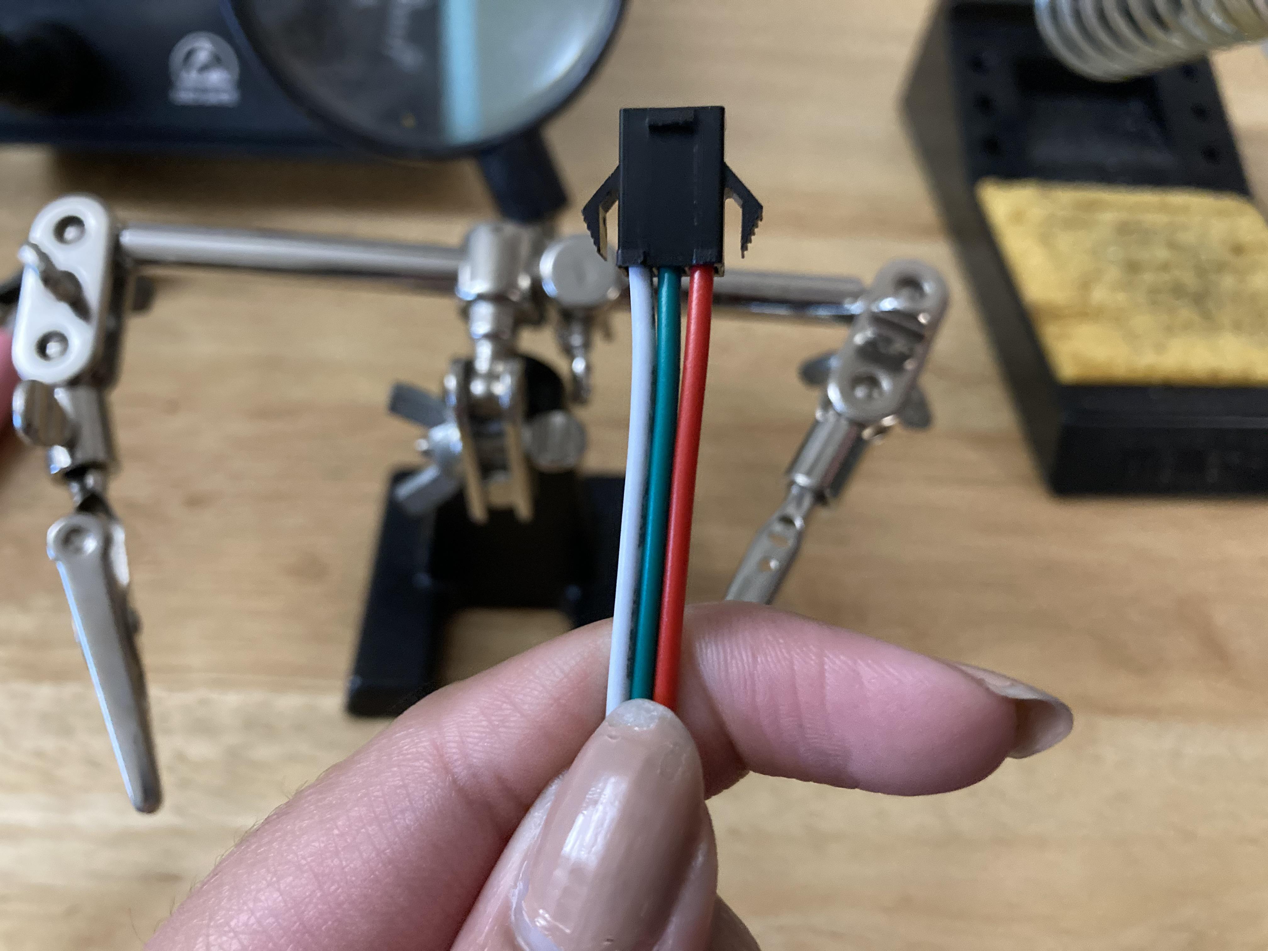
- You need one male and one female connector on each side of your LED strips
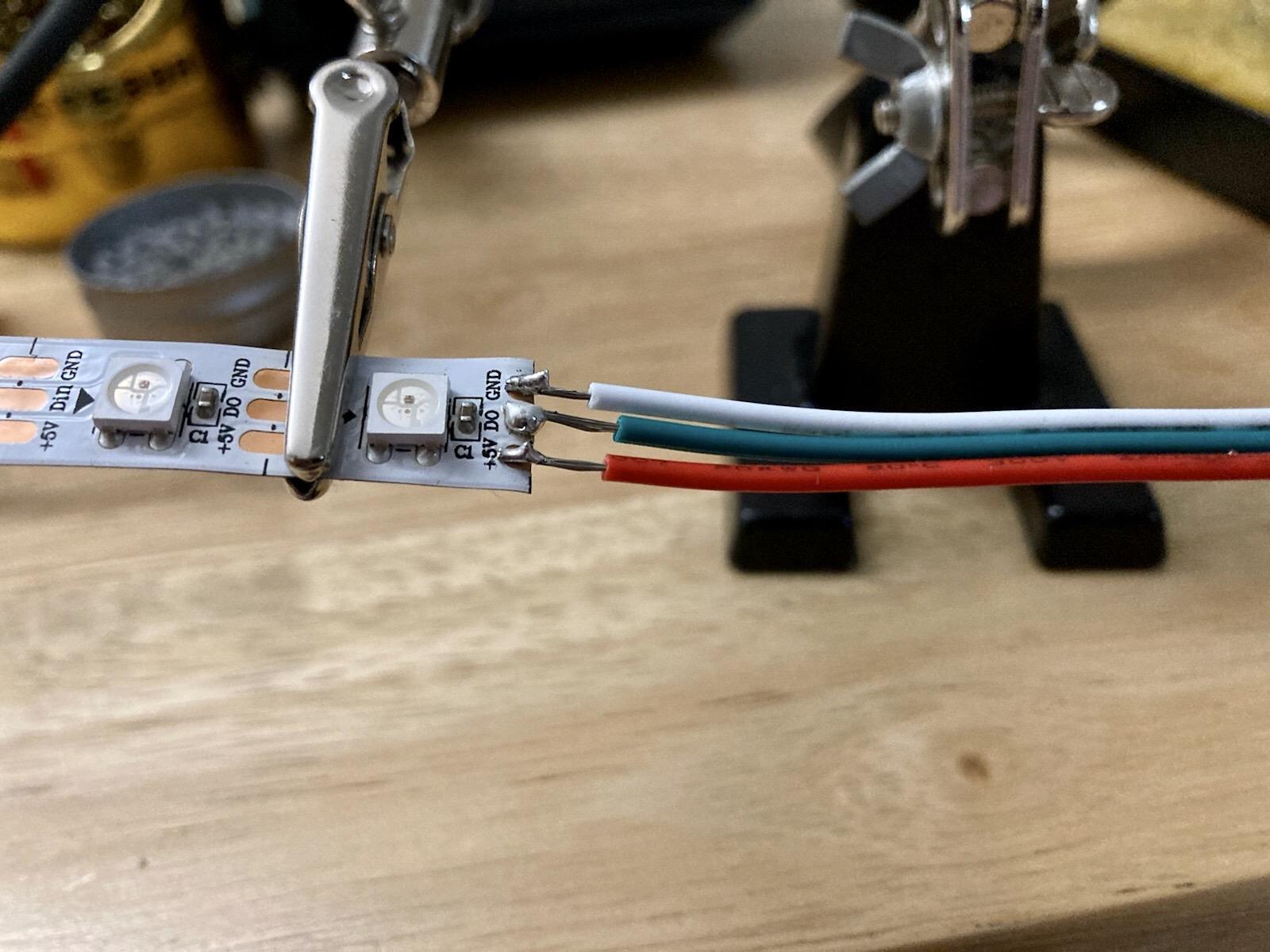
Important: make sure to solder the wires correctly to have the red to positive, green to neutral, and white to ground.
- Once you positioned your wires correctly, use helping hands or clamps to help you while soldering
- Set your soldering iron to ~600℉
- If your soldering kit comes with a sponge to wipe off excess solder, make sure to keep it wet to prevent potential accidents
- Then, carefully hold the tip of the soldering iron touching the copper on the LED strips while adding the solder
Laser Cutting the Diffusers
.JPG)
With a Laser Cutter:
- To cut the diffusers, create a new file on Adobe Illustrator based on your laser cutter's bed size. Create a Hexagon and size it according to your 3D printed base dimensions
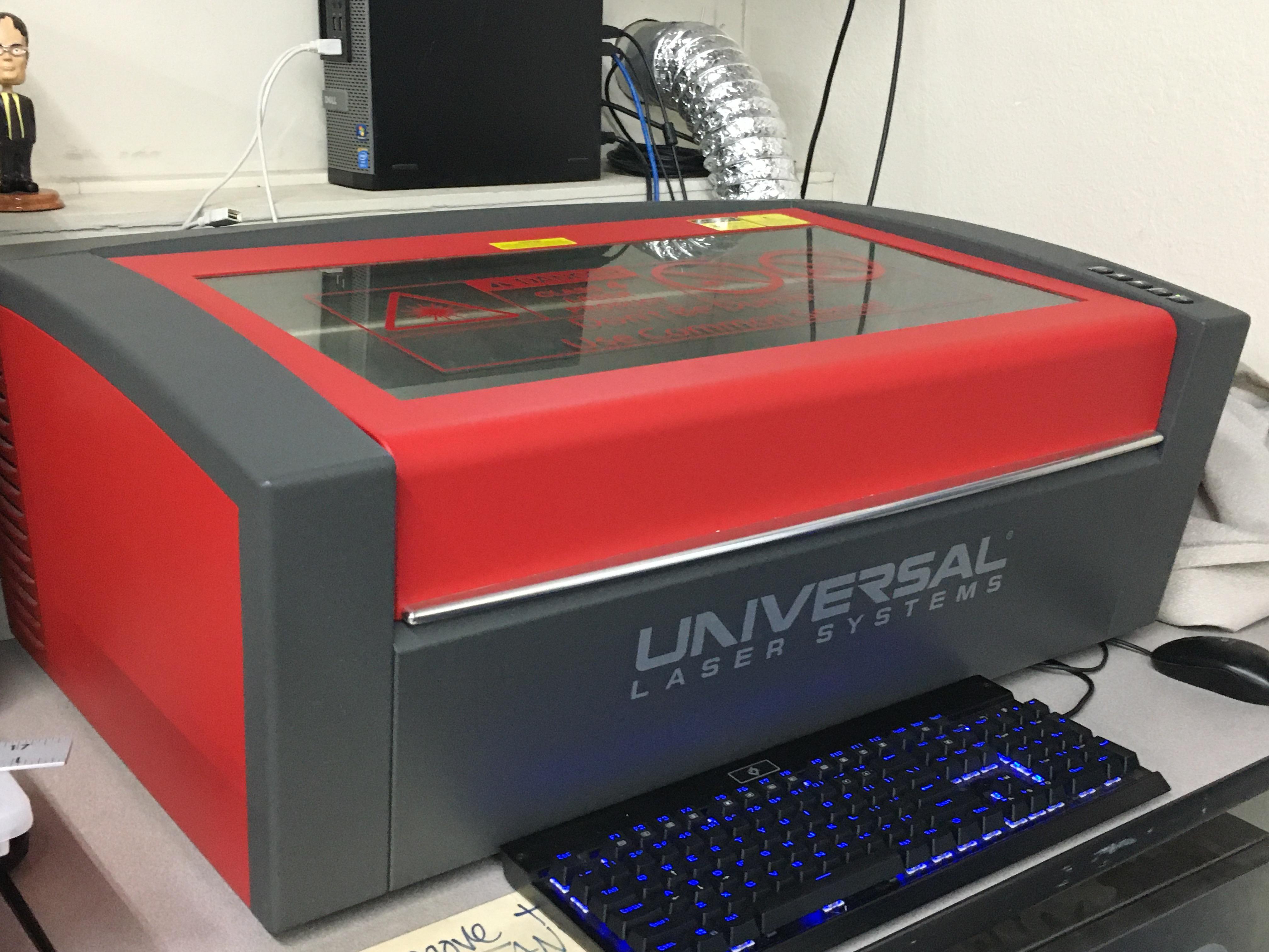
- If you're using a ULS as I did, make sure to set the color to 255 red and hairline (0.1 point) for the laser to cut
- Open the file on your laser cutter and change the settings to cast-acrylic while following your specific laser cutter's settings
Without a Laser Cutter
- If you do not have access to a laser cutter, you may use a jigsaw, acrylic cutting knife, or any other metal blade suitable for cutting acrylic
- Make sure to trace the outline on the acrylic before cutting to ensure proper dimensions
Assembling the Hexagons
.jpg)
.jpg)
.jpg)
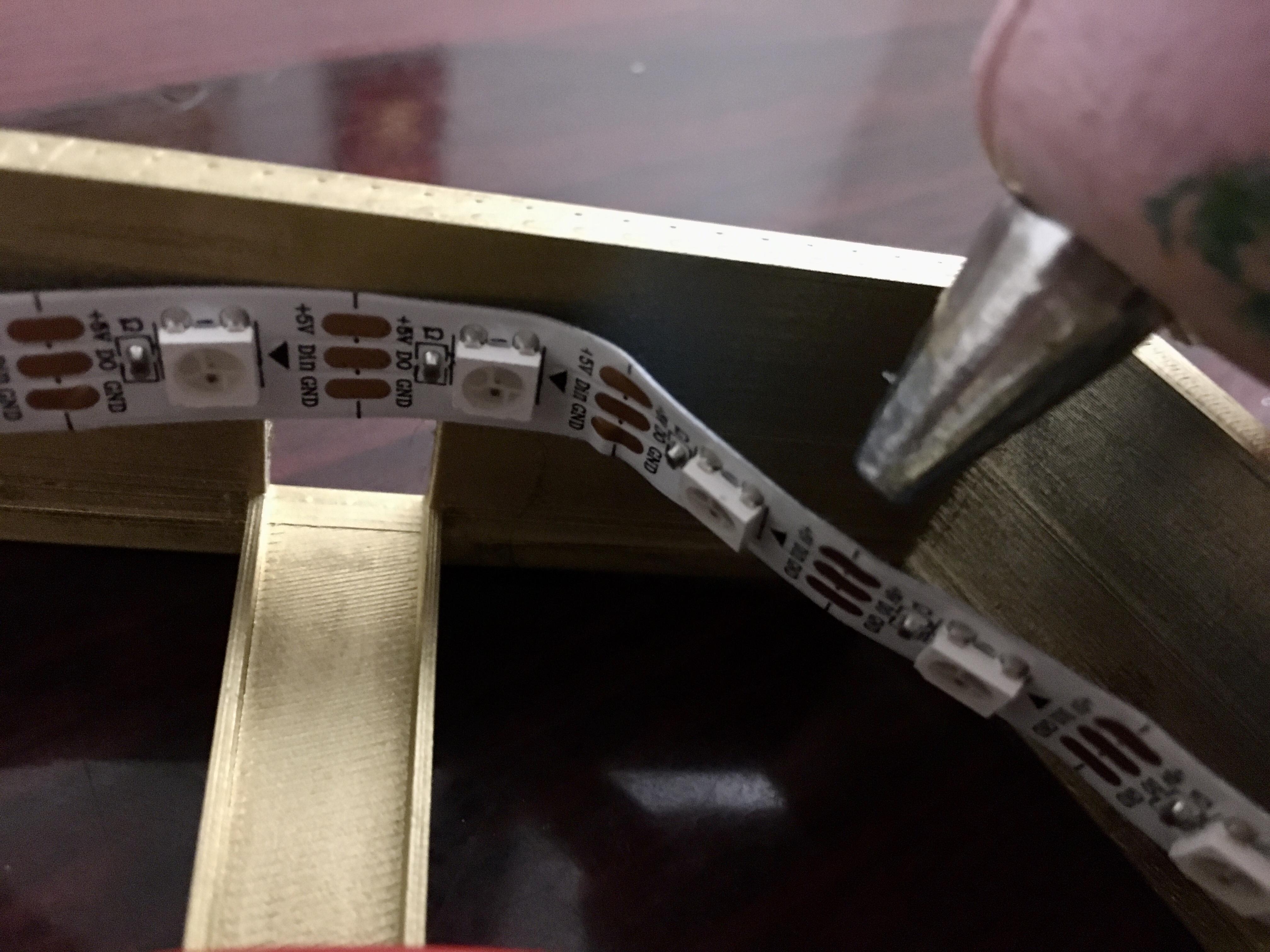
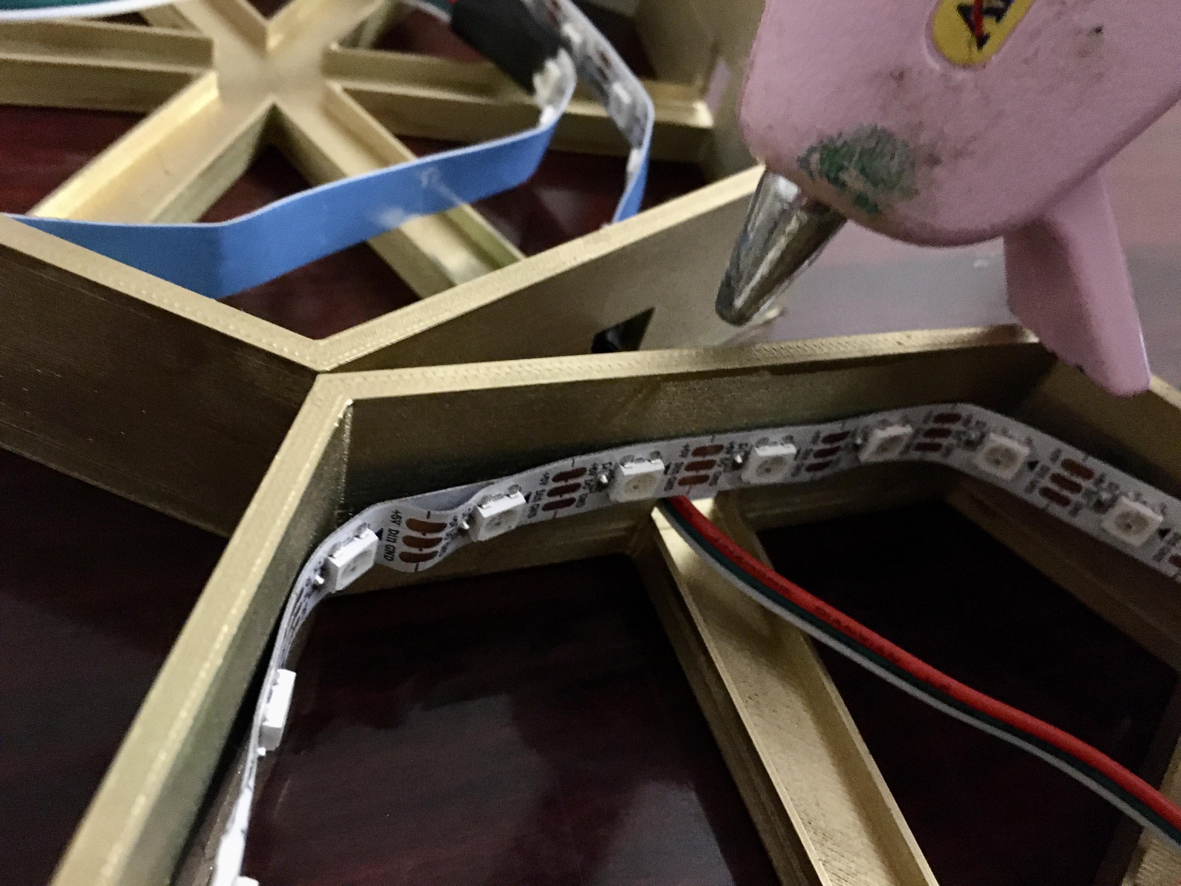
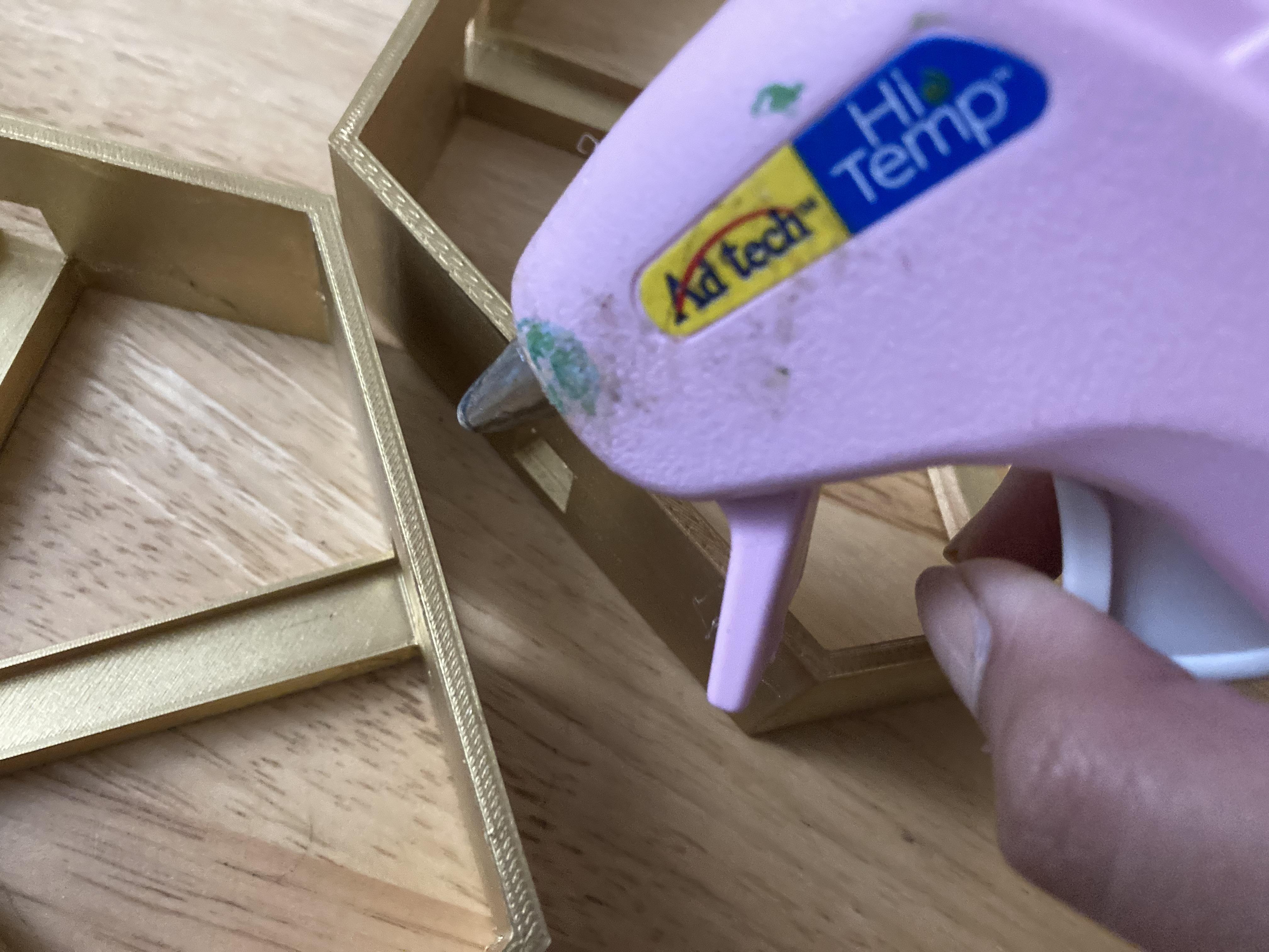
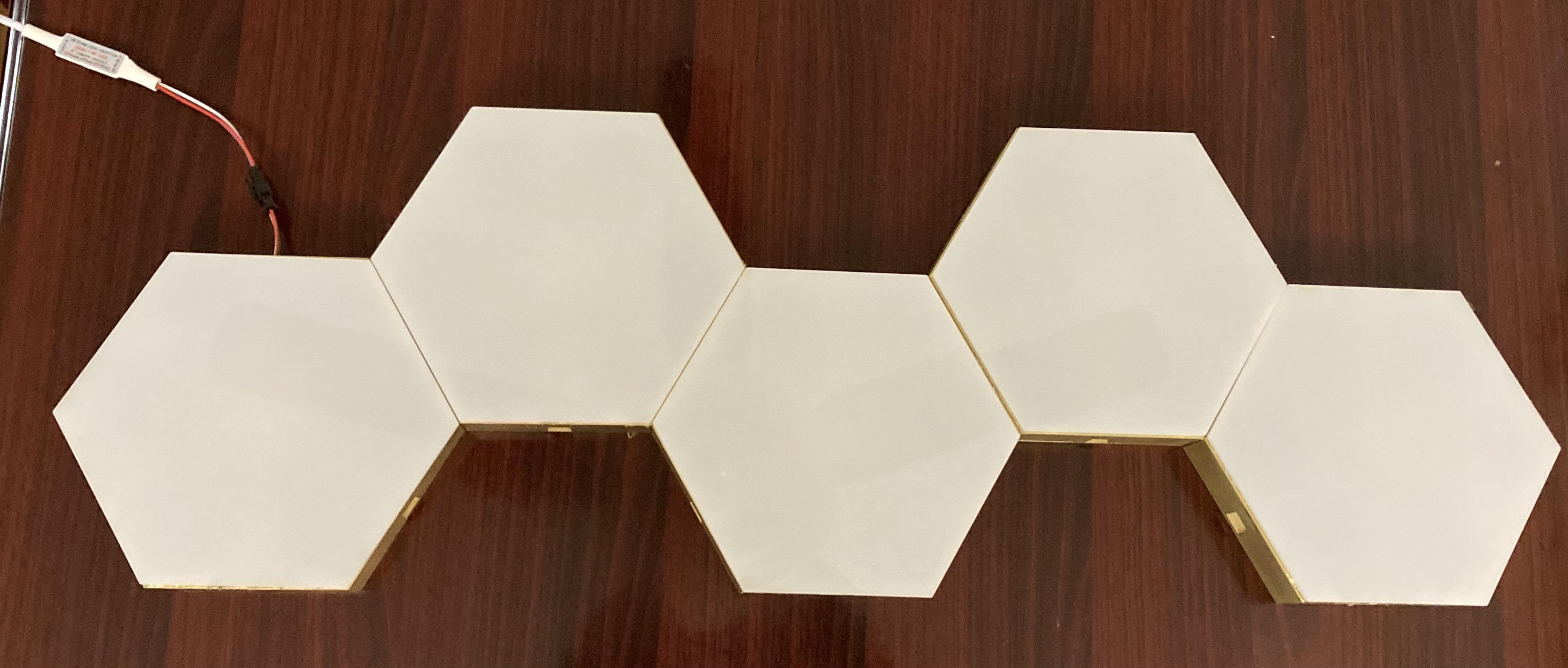
- Fit the LED strips through the hexagons and secure them using an adhesive
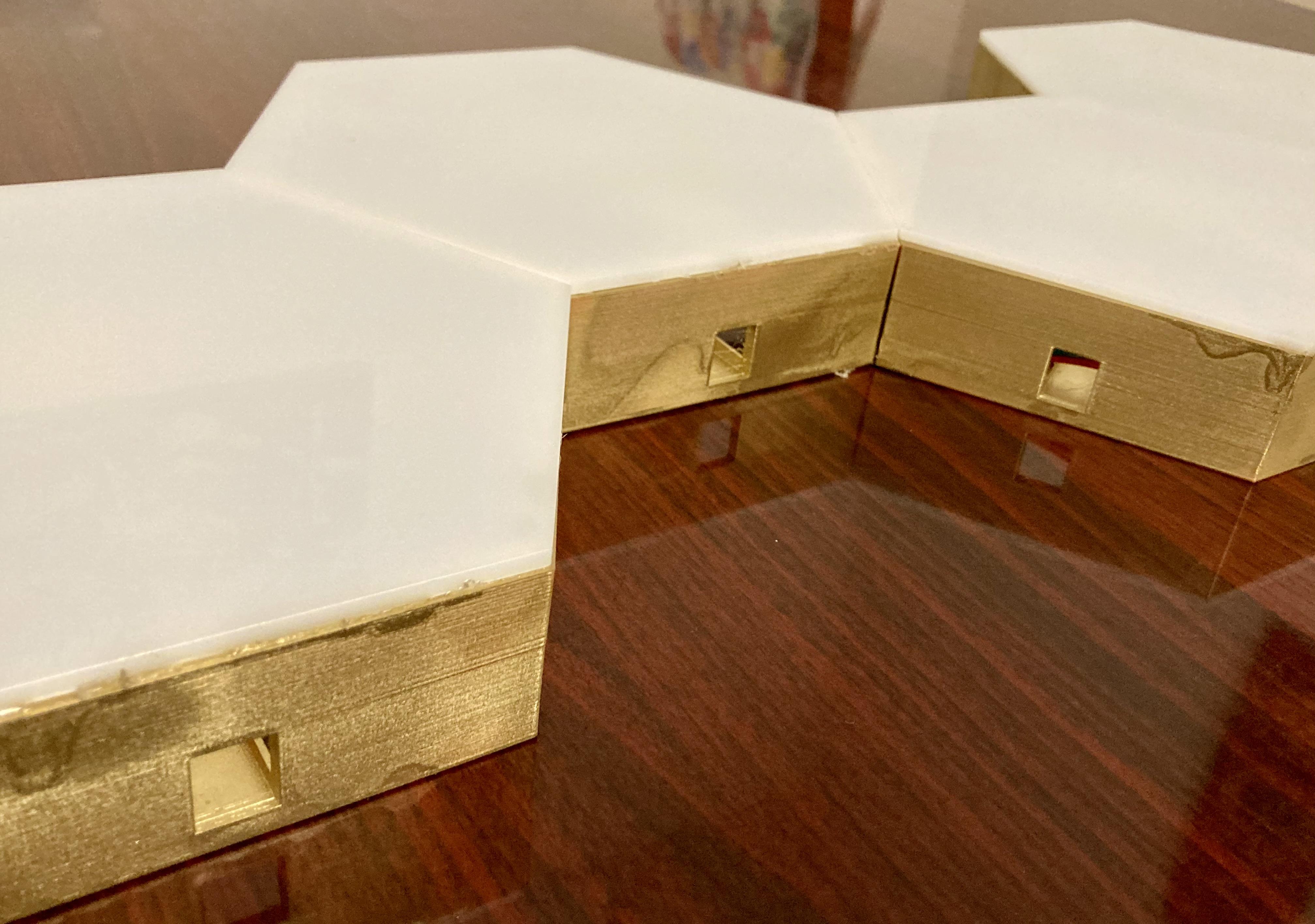
- Then assemble the hexagons together in the desired shape
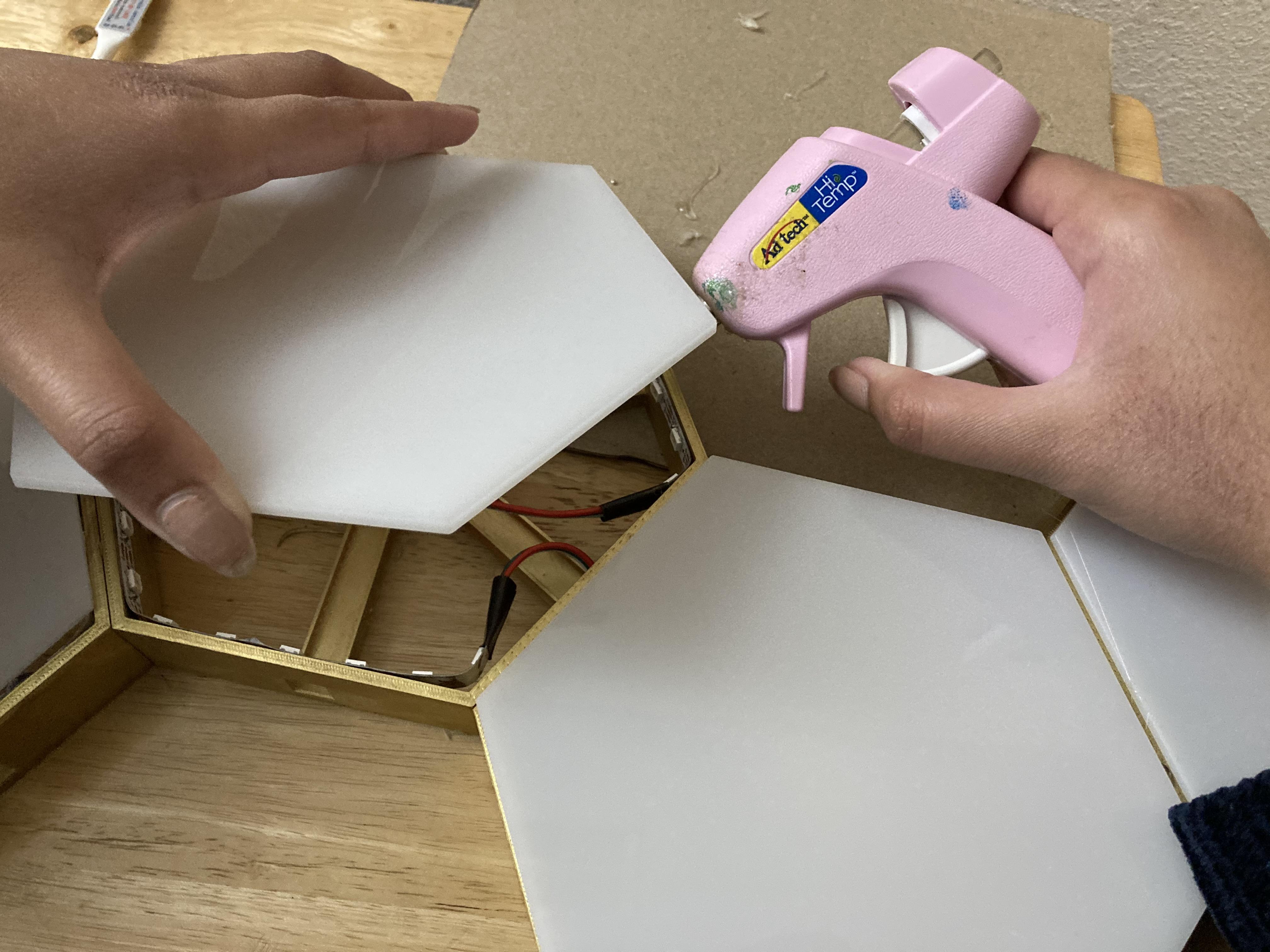
- Finally, attach the diffusers to the top of the hexagons
Tip: Though hot glue works, it's safer to use super glue or epoxy
Electronics
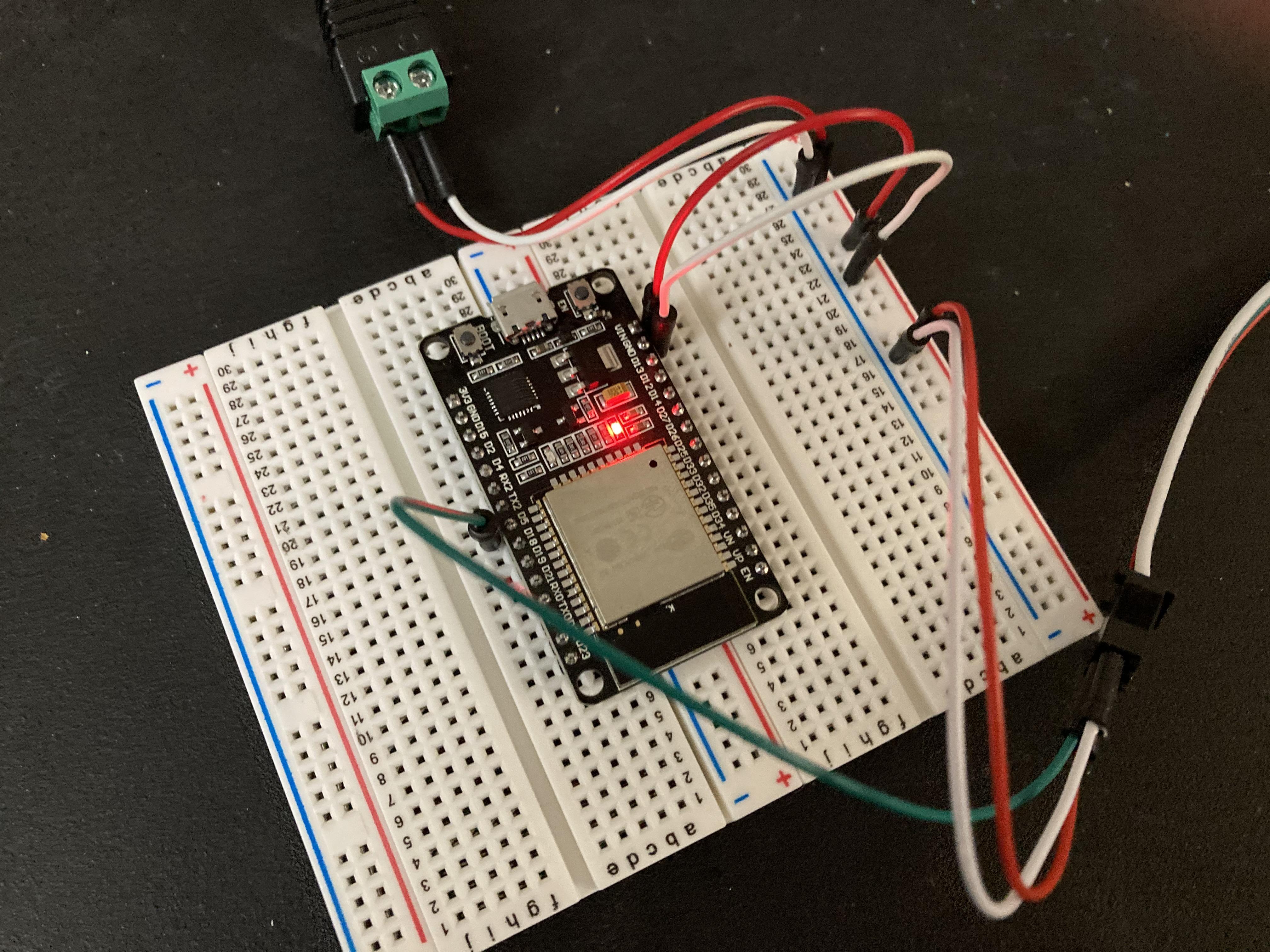
- Using an ESP 32, a 5V DC power supply, and jumper wires, connect your circuit to your breadboard as shown
- I had to use 2 breadboards for the extra pin but soldering your wires would be more practical and permanent
Setting Up the Blynk App
- Once you open the blynk app, create a new project using the ESP-32
- Blynk will provide you with an authorization code that you can use in your code later on
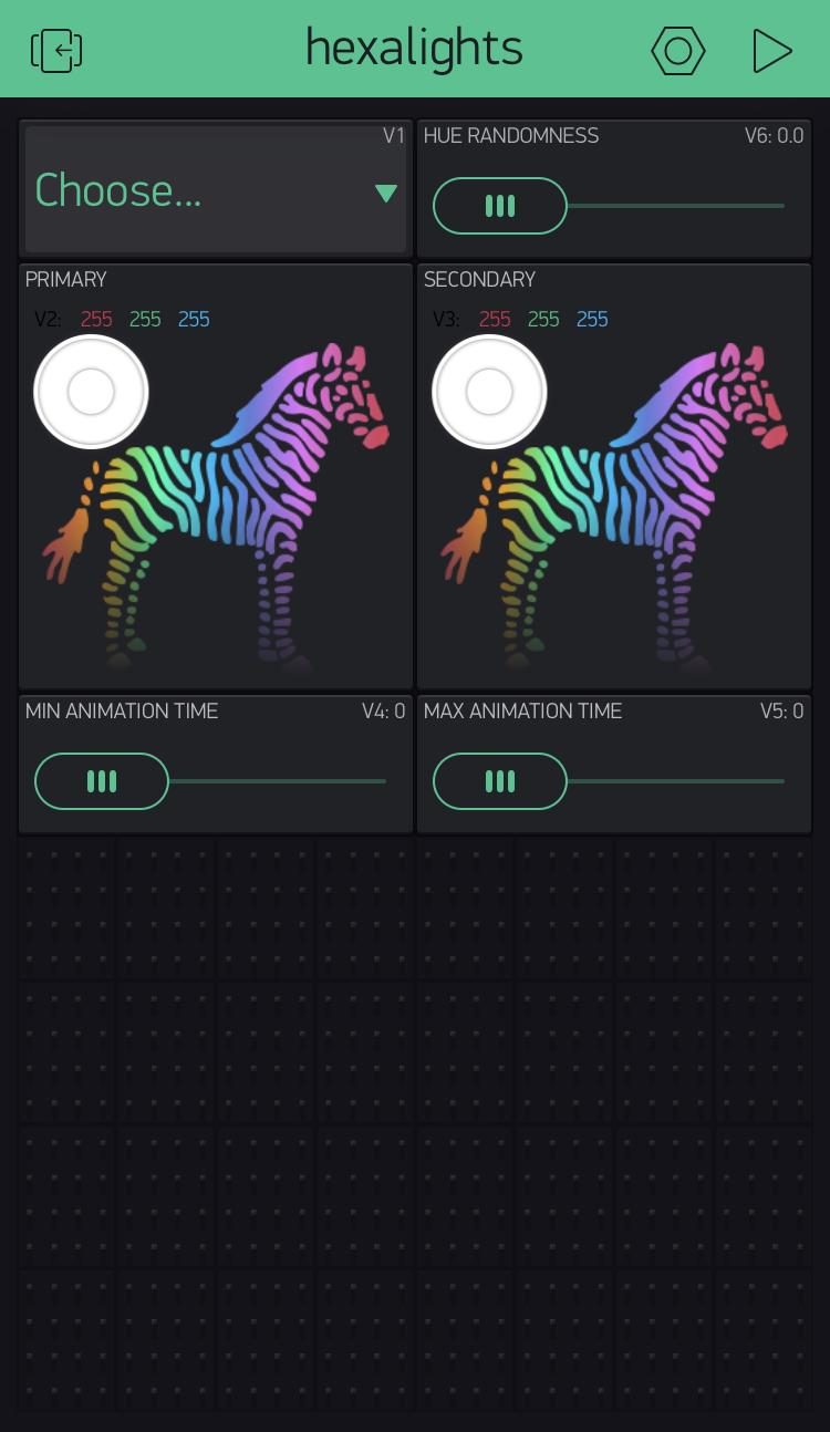
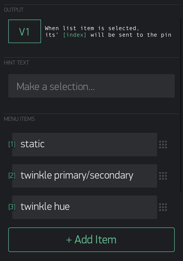
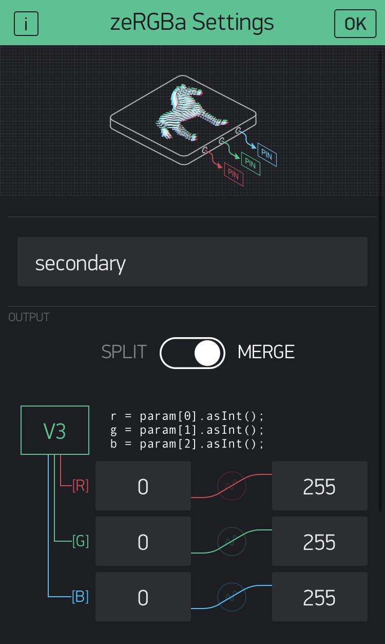
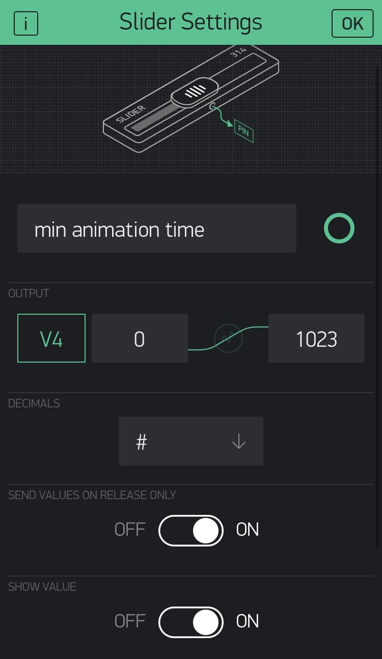
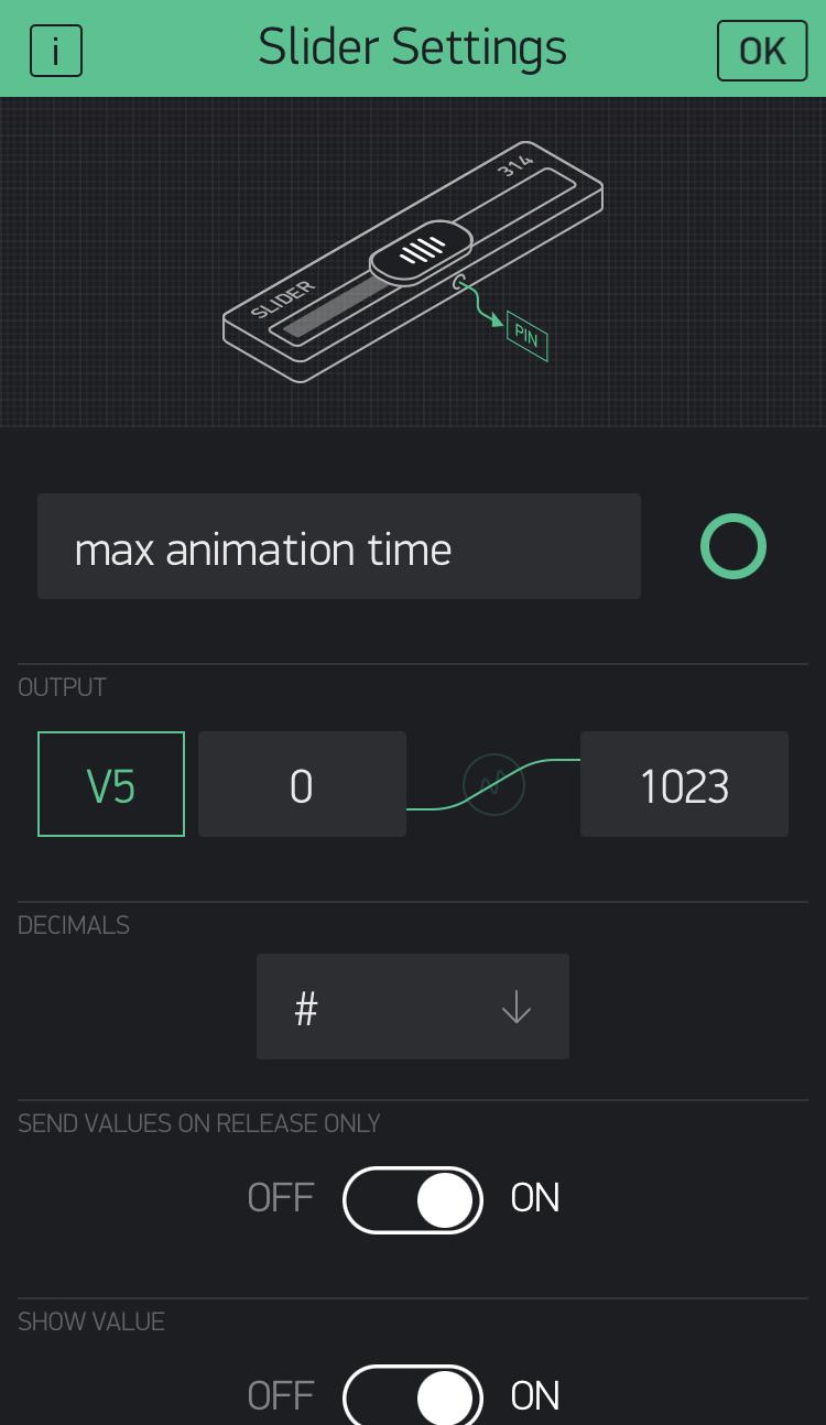
- For now, head to the panel on the right side of the screen to drag and drop the elements as shown in the first picture
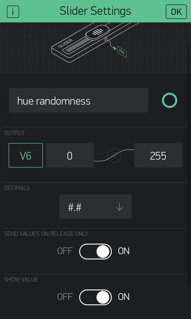
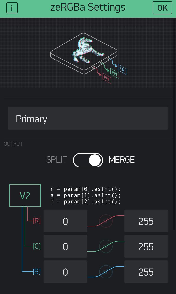
- Then, by tapping each of the elements, configure the settings as shown in the following images
Code Configuration
- The code used is from Hansi's GitHub page so please download both code files from there
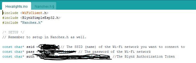
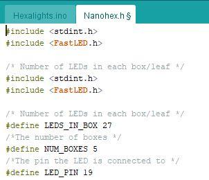
- First, copy and paste Hexalights.ino into a new Arduino sketch
- Nanohex.ino needs to be renamed to a ".h" file and I found that the best way is to copy and paste the code into a notepad and rename it there
- Once you have a ".ino" and ".h" file, move both of them into the "Hexalights.ino" folder to ensure that they appear in the Arduino workspace simultaneously
- You do need to modify the code for it to fit your design
- On "Hexalights.ino", make sure to add your wifi SSID, password, and Blynk authorization token
- On "Nanohex.h", change the number of LEDs in the box, number of boxes, and the pin on your esp 32 to match your project
Final Thoughts
.jpg)
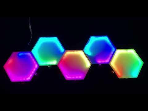
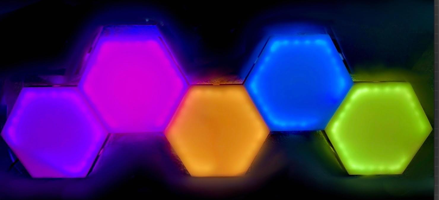
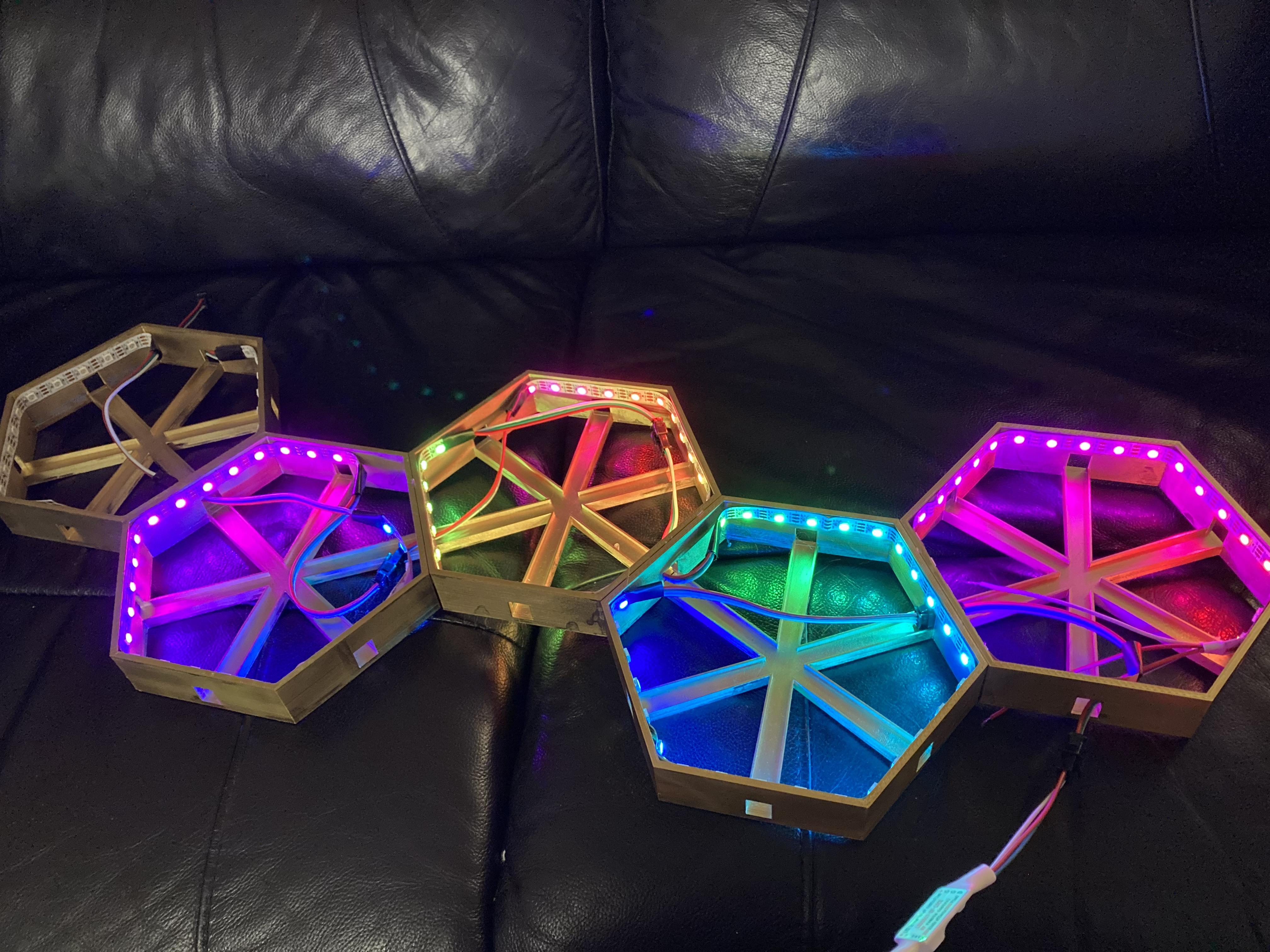
Since the LEDs can be changed, I had fun setting them to a rainbow effect :)
Overall, this was an incredibly fun project to make and I highly recommend trying it out! Although some parts were challenging, everything was worth it in the end. The lights look impressive on display and are sure to add an extra pop of color to any plain wall.
Thanks for checking out my tutorial! I hope you enjoy making your next LED project as much as I did!