NES Bluetooth Controller.
I based this tutorial on Jlang9's tutorial, though there are maybe others out there.
Adafruit do a tutorial too, but it deals with the SNES controller, so it's not 100% useful.
Parts you'll need.
- NES controller
- Sacrificial USB Cable to be cut up for the charger.
- Fine wire. I used some spare hookup wire for data for the power between plug and charger.
- Adafruit EZ Key - This basically pairs to PC's etc as a keyboard device, and sends a key press when you trigger it.
- 100mAh lipo battery - I also got this from Adafruit. it's got enough juice to run this thing, i don't know how long it will last between charges, but it's small, and does the job. i think those RC helicopters use these too, so that might be a source too. IDK
- charging circuit for the lipo - Also from Adafruit. i don't work there, just got all this stuff in the one place.
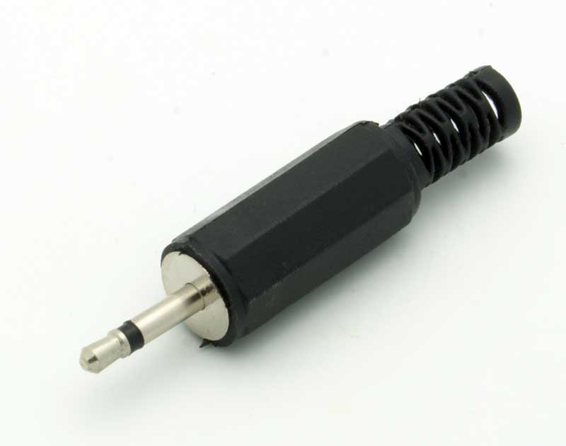
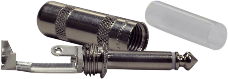
- 2.5mm mono plug - This is for a charging connector. it's a mono (not stereo) version of what looks like a mini the headphone plug. I don't know what Americans call them, maybe 0.0984251969 inches or something.
- 2.5mm mono socket - this is the socket to be used on the controller. it will be fitted where the old cable used to be.
- SPDT or DPDT switch - basically, the smallest slide switch you can get, this needs to be at least double pole single throw. which means that there are at least 3 connections on the bottom.
Tools you'll need.
- Dremel multi tool
- Soldering iron
- multimeter
- hot glue gun
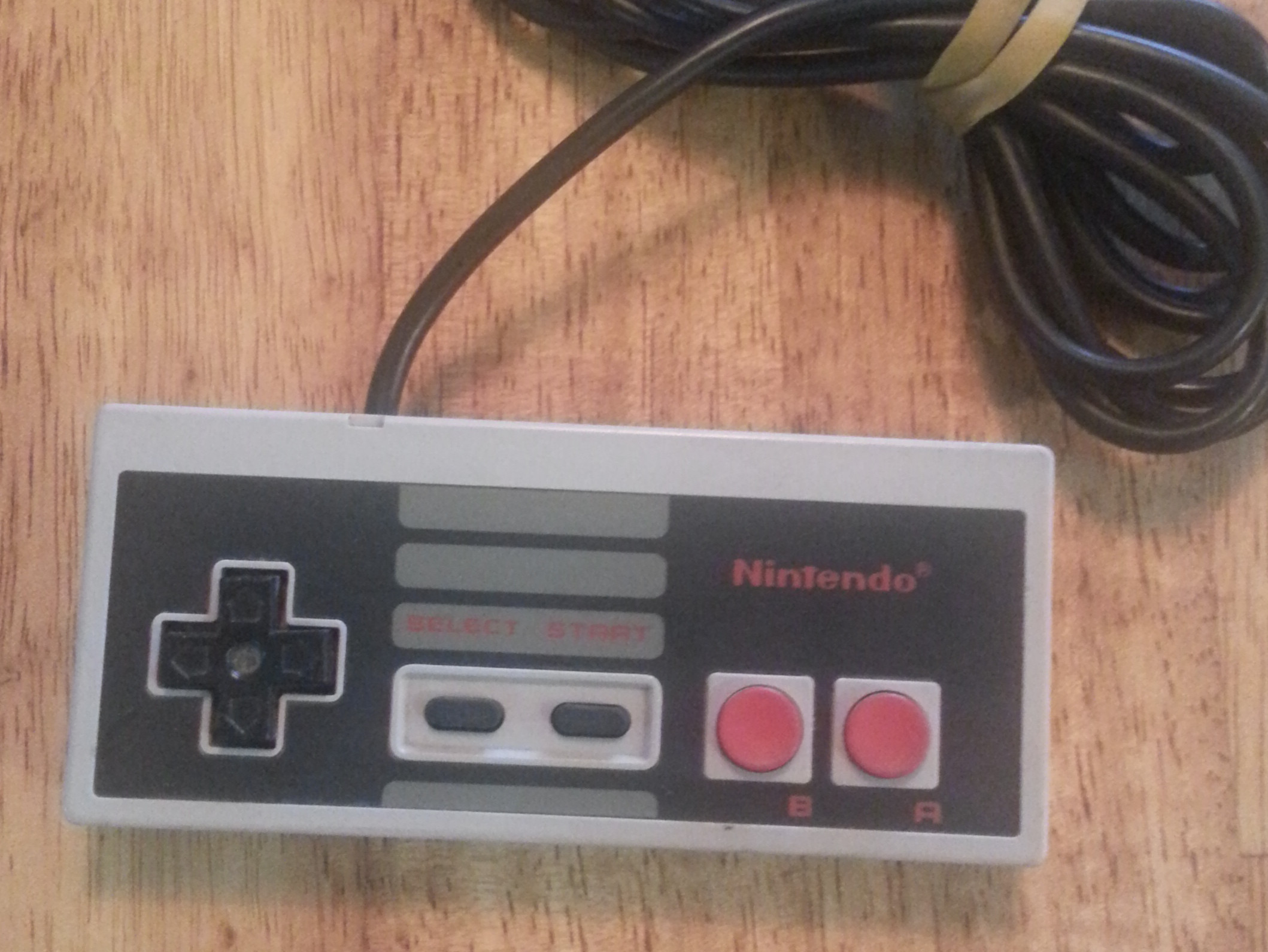
Open Up Your NES Controller
Open up your NES controller, and be sure to keep the screws in a safe place. Also hang onto the buttons, because your cat will try to eat these.
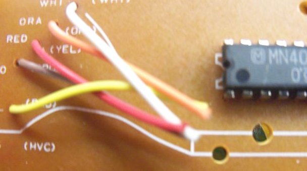
Cut the wires going into the board. de-solder the chip, and also the pin where the yellow wire connected. Leave the rest of the wire pins, because they're going to get cut off in step 2.
How It Works
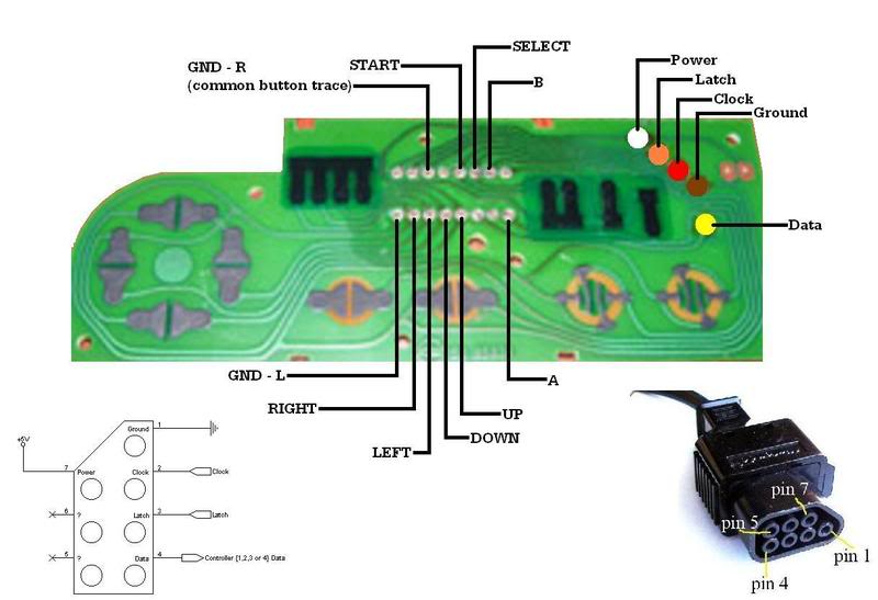
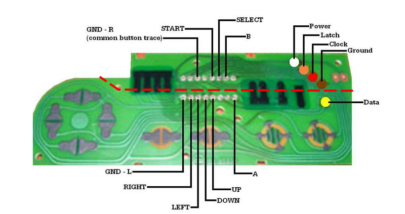
How these controllers work is that for each button there are at least 2 black pads under it. One of these pads will always go back to ground (GND-L/GND-R), and the other will go somewhere based on what button it was.
When you push the 'A', the coating on the bottom of the button joins both sides of the black pads.This completes a circuit between ground (GND-L/GND-R) and the 'A' pin of the chip. This signals the Nintendo, to make your double dragon guy jump off a ledge and die.
We're going to use most of this system, but connect the all the buttons to inputs on the EZ-Key, and the GND-L to the ground on the EZ-Key. After we do this, pushing a button will complete the circuit, but this will make the ezkey send a keyboard keypress to the computer.
Cut It Up
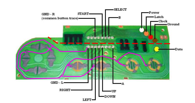
Using your dremel tool, cut along the red dotted line shown in the picture, you should have already removed the chip, because it's in the way of where we're cutting. We don't need the resistors or the chip, but they can stay where they are.
In the next step we're going to use the bottom row of the holes the chips legs were in to connect wires. the labels in the image above show what each does.
It's very important that the circuit line between GND-L and the pads isn't broken. You can use a multimeter to probe this if you're not sure. The second image shows that if you follow the The hole labeled GND-L, you'll connect to one half of every button pad
In the same way, don't break the trace between the A button, and the A-hole (heheh.)
The way we have to cut the board will cut the traces to Start, Select, B and GND-R, but we can deal with this later.
Solder to the Board
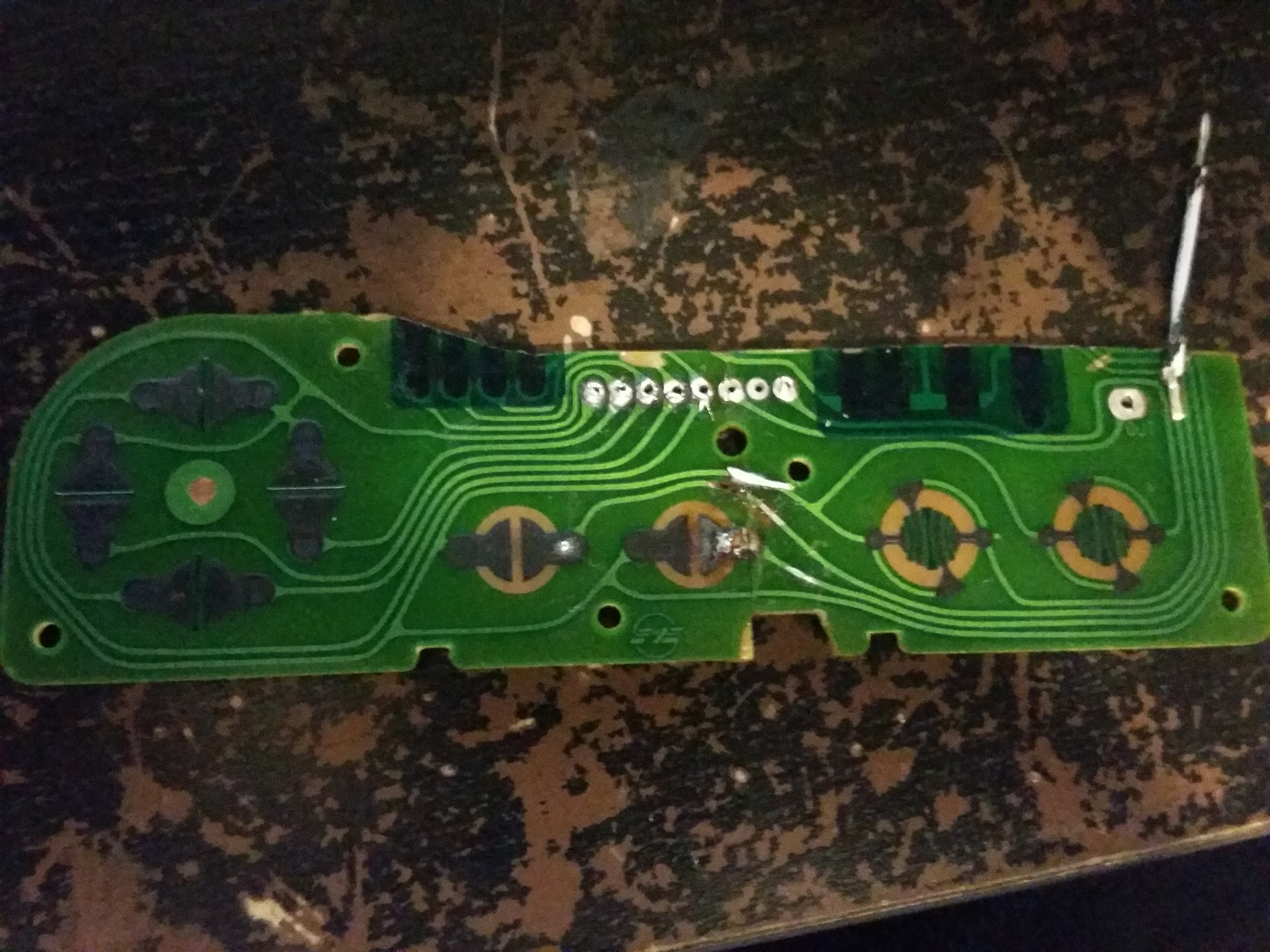
Now because we had to cut through the traces for the B, Start and select buttons, we can't use the holes where chip came out of. We need to solder direct to the board.
Using an exacto knife, carefully scrape away only the top coating of the trace for the B button, as shown in the photo. you should see the copper trace underneath.
Strip the end off, and solder a 5cm (1 31⁄32 inch) wire pointing to the top of this board into the locations shown in the picture. The wire I've soldered in is photo is too short, also I snapped this board because I'm an idiot. don't snap the board.
Put the buttons, rubber pads, and the bit of circuit board back in the controller case, and make sure the buttons push down and right. my start and select feel a bit different, but still push.
This is also a good time to make sure that your Start and Select button wires don't interfere with the locating pins on the remote body. If they do, it's better to solder them again, because bending them can pull the black button contacts off.
Dummy Fitting and Looking at Wire Lengths
Take the controller apart again, but keep the controller board and buttons still in place in the front half of the controller shell.
Dummy fit the EZkey in place, I put mine above A/B buttons, with the pins 0-12 closest to the controller circuit board. It kind of sits a little under the circuit board.
Have a look at what bits of the inside of the controller housing might need to be cut out, i can't remember which i did, but you'll be able to tell. I think some of the wire holders around the opening for the wire mouth. This will also give you an idea how long the wires will need to be to fit join to the board.
Fitting mine in wasn't that hard, but there is a trick to getting it together. i have to put the buttons and controllers' board in place first (and line it up with the alignment bits) when this goes in half of the the ezkey is under it, and half pokes out the top of the controller, it just needs to be nudged in further so the case can close.
Once you have an understanding of how long each wire will need to be, cut it, and strip the end to solder onto the EZ Key in the next step.
Soldering to EZ-Key
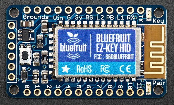
For this step, we're mostly just concerned with the bottom row (and one Ground on the top row)
The default mapping of keypress produced by the bottom row of holes is :
- #0- Up Arrow
- #1 - Down Arrow
- #2 - Left Arrow
- #3 - Right Arrow
- #4 - Return
- #5 - Space
- #6 - the number '1'
- #7 - the number '2'
- #8 - lowercase 'w'
- #9 - lowercase 'a'
- #10 - lowercase 's'
- #11 - lowercase 'd'
You can remap afterwards, but I couldn't get that working, so i just used this as
- #0- Wired to controller up
- #1 - Wired to controller down
- #2 - Wired to controller left
- #3 - Wired to controller right
- #4 - Wired to controller start
- #5 - Wired to controller select
- #6 - Wired to controller A
- '#7 -Wired to controller B
- Ground Wired to GND-L
Probing the Charging Circuit.

This step deals with wiring the charging circuit. To do this, it's very important that we know which pins on the plug go to which pins on the socket.
Get your plug and unscrew the plastic so you can see the terminals like in the first picture, then use a multimeter to confirm that the connections are what i've described in the first picture
MAKE SURE YOU CHECK THIS, NOT EVERY CONNECTION IS THE SAME, REVERSE POLARITY IS BAD NEWS AND MIGHT KILL YOUR PC IF YOU CHARGE IT FROM ONE.
After checking that, connect the plug into the socket, then probe again, this time checking which terminal (tab) at the back of the plug connects to which terminal (tab) on the outside of the socket. each tab on the socket should only connect to one tab on the plug.
Make a note of this what connects where, because we'll want to wire the + on one side to the (+) on the other.
Wiring the Charging Circuit.
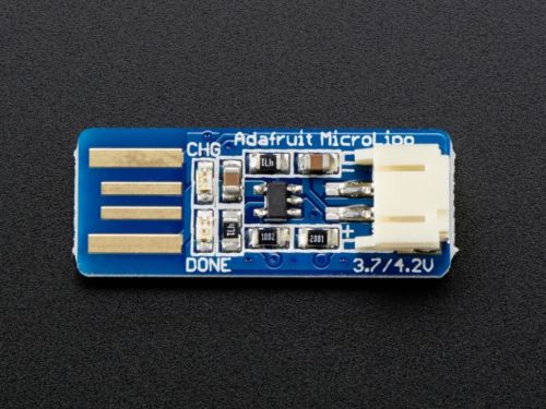

I modified the charging circuit a little to save space. Originally this formed a USB connector on one end (IN) and had a plug/socket for the +/- OUT.
I dremel cut half the length of the USB part, and removed the plastic plug connector on the other end, then just and soldered these bits on the board to save space. this might not be necessary, but it won't hurt (unless you mix up polarity).
Because of this when i refer to the + in and + out of this charging circuit. the + in is the USB looking side, and the out is the side i removed the plug from.
- Solder a wire from tip connection of the 2.5mm socket to the + in of the charging circuit.
- Solder another wire from the sleeve connection to the (-) of the charging circuit input. I don't think it says (-) on this charging circuit, but you can infer from it being the one not labelled (+)
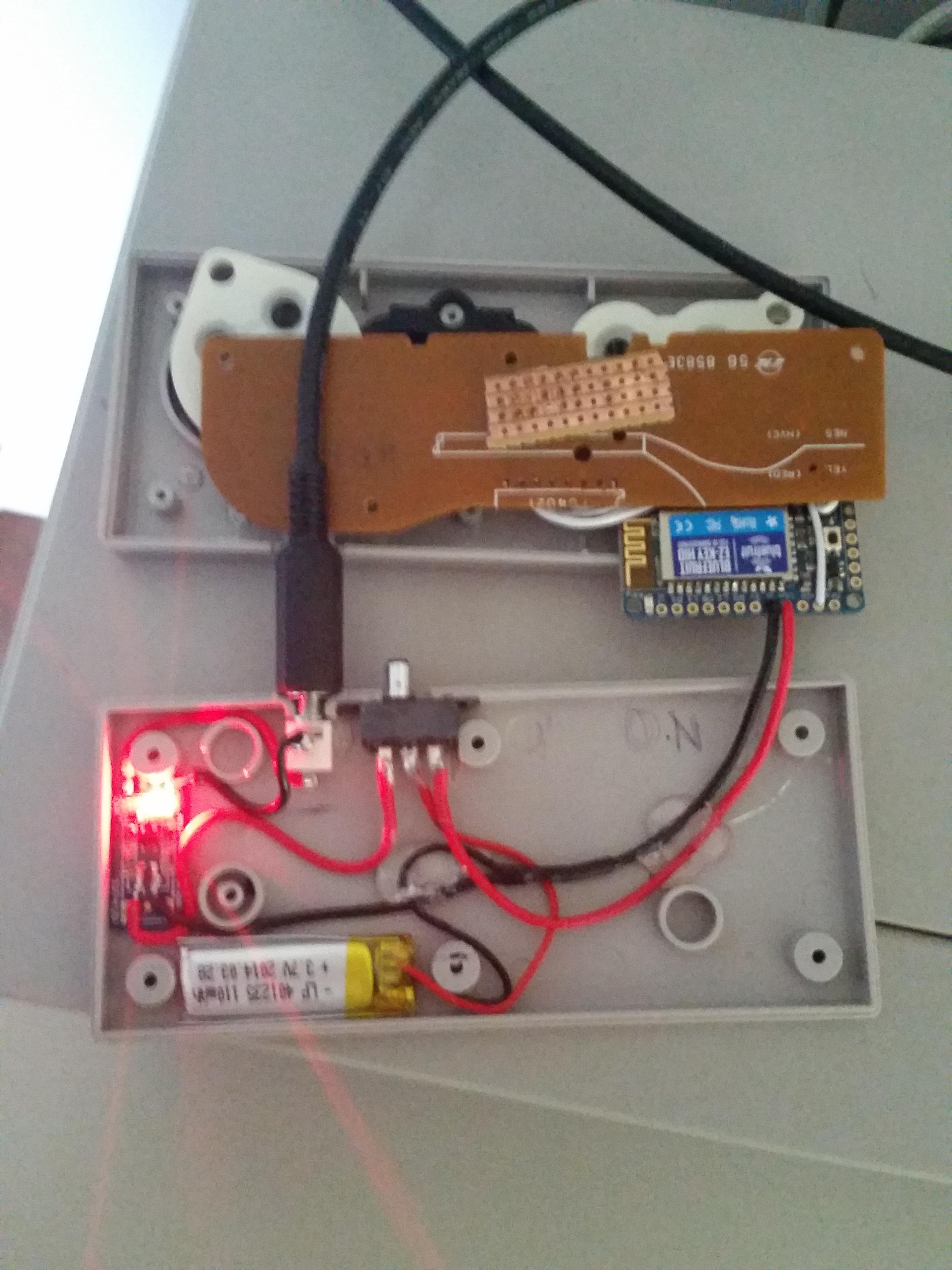
- move the switch to the left, as in the photo above
- Solder a wire from the + of the battery (red wire) to the centre tab of the switch.
- Solder a wire from the + out of the charging circuit to the left tab of the switch.
while you don't need to use red for (+) and black for (-), if your new to electronics it can help to identify stuff, it also makes it easier to work on down the track, especially when some of the parts you're using already use this colour key.
I Can't stress enough that you check polarities, especially if you're new to electronics. The only time I've messed up building something was when I've done something dumb with this.
Final Wiring

Connect the remaining tab on the switch to the V-in on the EzKey. it's not a bad idea to heat shrink or insulate these (+) connections when you're done.
Finally make a Y shape out of 2 bits of wire, and use it to join the (-) out of the charging circuit with the (-) of the battery, join the final end of this Y to the 'G' socket on the EzKey.
Final Fitting. and Tests.


Refit the components and use the dremel or exacto to make a cutout for the switch. Close it up to make sure everything fits before glueing the switch etc all down. If the battery has any charge, you should be able to turn it on and pair with a PC at this time.
Pairing instructions can be found here.
After pairing, open a text file and check the keys output what they should. if it's all working correctly, you should get 1 and 2 coming out when you press a and b. start should hit enter, select should hit space, and you should be able to use the up down left right like the arrows on a keyboard.
If any buttons don't work as expected, check to make sure none of your solder is bridging between solder points.
if no buttons work, but the device pairs, it may be the ground isn't connected correctly.
Wiring the Charging Cable.
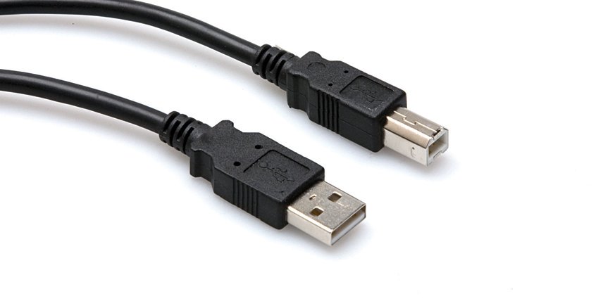

Get your donor USB cable, I used a USB-A to USB-B cable, but you can use whatever. a phone charging cable might be too thin to easily work with, but idk.
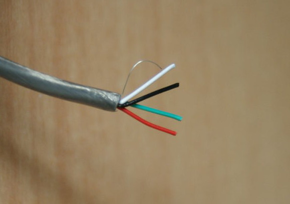
Cut off the cable end that ISN'T USB-A, then strip the outer core, exposing some silver stuff. strip that back and you should get 4 wires, red, green, black and red.
we only care about black and red, so i folded the white and green wires back, and taped them to the body of the cable.
put the cover onto the cable first, then solder the wires to the tip/sleeve. The first couple of connectors i made like this i forgot to do the right order, and felt like an idiot when i had to unsolder, and fit the cover on.
Optional
I only use my controller with one home media PC, so I paired it (using the button on the EZKey) with the controller openned up, then put it together.
Having to open the case to pair is a bit ghetto, but there is a fix.
On the EZKey, some of the unused pin holes are '3v' and 'PB'. PB is a pairing trigger, if it's connected to 3V it will trigger the "Pair" action on the EZKey.
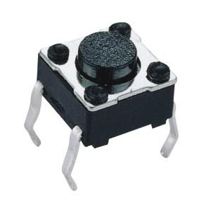
Add a wire to each of these pin holes, and then solder the other end of each wire to a momentary switch. these switches have 4 legs, make sure you solder to 2 of them which are only connected when the switch is pressed.
Drill a small hole in the back of the controller, and put the momentary switch upside down over it, so the button can be pushed through the hole. then glue the switch in place.
Make sure you don't get glue on the button itself, or it might not push properly.
You could also add an external LED so that you can tell the paired/power state of the unit, but I haven't looked into the wiring of this.