NEOPIXEL Pro Max
.gif)
.gif)


Hello Everyone.
So, this is a NEOPIXEL LED, which is a little larger than a standard PIXEL.
By using eight Regular RGB LEDs and a WS2811 LED driver to create a single pixel that is around ten times the size of a Regular RGB LED, I created a unique addressable RGB LED.
The WS2812 LED is covered in transparent epoxy at the center for encasing the R, G, and B along with the WS2812 Chip.
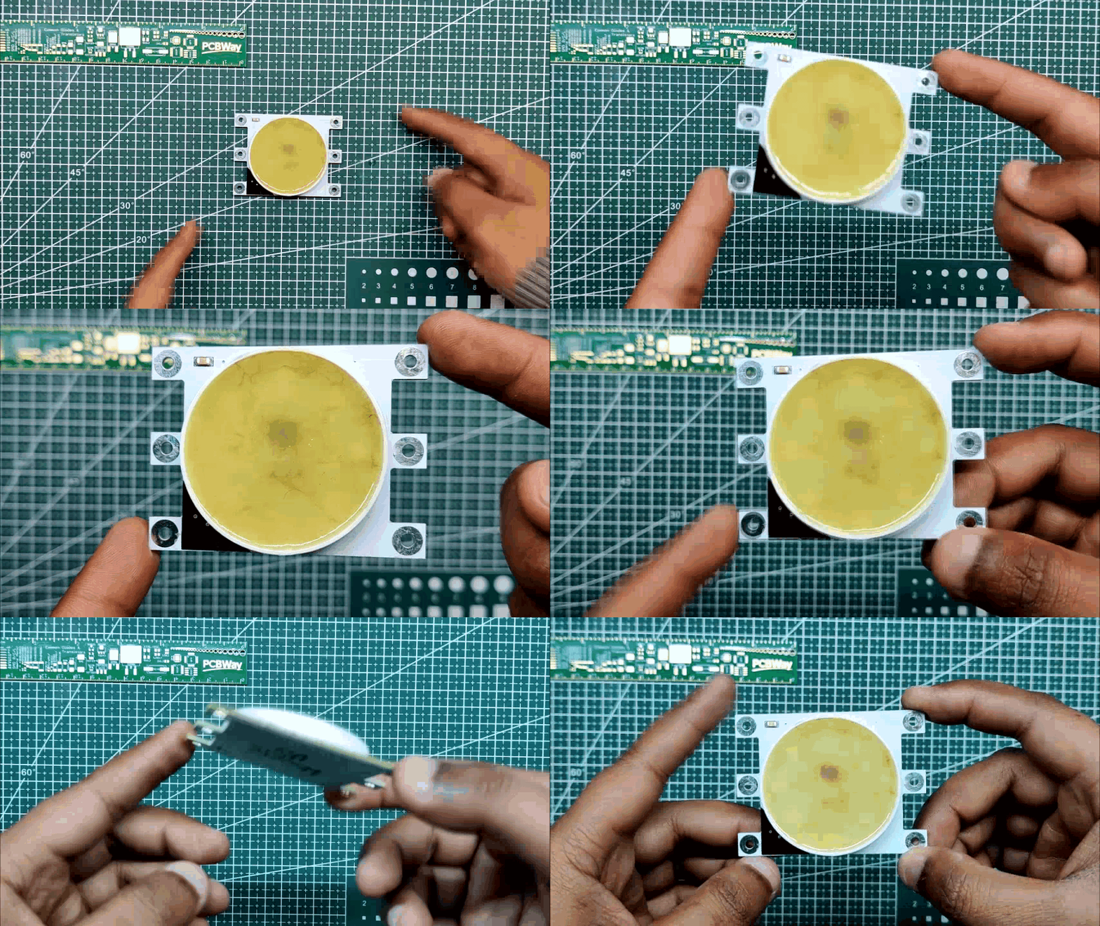
The Huge Edition of the Neopixel also has epoxy-covered circuits that are all enclosed in resin, which will prevent the board from outside causes or getting shorted out, etc., in order to recreate this concept.
This Instructables is about the whole construction process of this LED board, so let's get started.
Supplies
Following are the materials used in this built-
- 5050 RGB LEDs
- Custom PCB which was provided by PCBWAY
- 100nF 1206 Capacitor
- 3R0 Resistor 1206
- 3D Printed Ring
- WS2811 Addressable LED Driver IC
- Solder paste
- Arduino Nano for controlling the Pixel
Issues With Version 1


Let's review the last version of this project and identify its flaws before we begin this one.
https://www.instructables.com/WS2812-Big-Edition/
I included the LEDs in the previous edition in a 3S/3P configuration, which implies that three LEDs were linked in series and three in parallel.
LEDs need 12V to operate according to the arrangement, while the IC only requires 5V.
Why not step down the 12V for the IC to function by adding a resistor between the 12V and VCC of the IC, you might be asking.
That does fix the board, but since the LED requires a 12V source for power, we still require a second buck circuit in order to operate this setup with a 3.3V MCU.
I added jumper wires to link the tracks for each LED that wasn't being used in order to keep things simple and functional.
The configuration was working but needed improvement, so I made the necessary adjustments and connected all the LEDs in parallel. I even added connection pads on both sides to allow for the addition of multiple LEDs.
Version 2 Design


I created the circuit by using the WS2811 datasheet's schematic as a guide, and I utilized 8 RGB LEDs linked in parallel with the IC.
To reduce the current flowing to the RGB LEDs and then to the IC, I placed two resistors between VCC and the RGB LED positive wire.
I added six CON1 Pins to VCC, GND, Din, and Dout in order to connect with this setup. (Two CON1 Pins each are linked to VCC and GND.)
I created the board layout after completing the schematic by placing all the LEDs and other components in the center in a circle so that they can subsequently be covered with epoxy. I built an 8mm-diameter through-hole pad with a 4mm hole to connect to this massive neopixel, allowing you to attach any metal plate or wire to it.
To connect with this neopixel, I intend to use Aliogator clips.
Here's the datasheet of WS2811 IC.
PCBWAY
.gif)
.gif)


I sent the finished PCB to PCBWAY for samples after finishing it.
Since the WS2812B is white and the white solder mask looks fantastic in general, I decided to use it for this project.
The PCBs arrived in less than a week, which was impressive.
In terms of overall quality, it was outstanding. Each of the 20 boards I bought was flawless.
I've been using their service for a while, and I must say that the PCBs I received were excellent, just as I had hoped.
Check out PCBWAY for getting great PCB service for an economic price and high quality!
Board Assembly
.gif)
.gif)
.gif)
.gif)

- Board Assembly Process begins by first adding solder paste to each component pad one by one.
- Next, using a tweezer, we pick and position each SMD component in its designated location.
- Following that, we carefully lifted the entire circuit board and set it down on the Mini SMT Hotplate, which heats the PCB from below up to the solder paste melting temperature. As soon as the PCB reaches that temperature, the solder paste melts, and all the components are connected to their pads.
- PCB is now fully assembled.
Testing

.gif)
.gif)
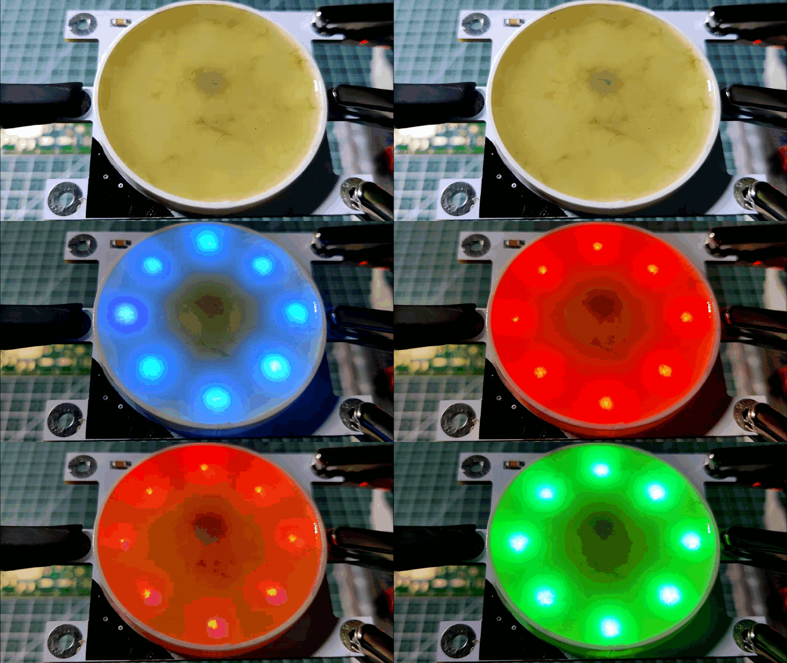
We utilize three Aligator clips attached to jumper wires to test this arrangement. To connect the neopixel to an Arduino nano board, we attach the alligator clip to its rounded pads.
For testing this pixel, I've used Adafruit's Button Cycler code connected to an Arduino Nano.
Here's the code-
#include <Adafruit_NeoPixel.h>

#define BUTTON_PIN   2    // Digital IO pin connected to the button.  This will be
                          // driven with a pull-up resistor so the switch should
                          // pull the pin to ground momentarily.  On a high -> low
                          // transition the button press logic will execute.

#define PIXEL_PIN    6    // Digital IO pin connected to the NeoPixels.

#define PIXEL_COUNT 1

Adafruit_NeoPixel strip = Adafruit_NeoPixel(PIXEL_COUNT, PIXEL_PIN, NEO_GRB + NEO_KHZ800);

bool oldState = HIGH;
int showType = 0;

void setup() {
  pinMode(BUTTON_PIN, INPUT_PULLUP);
  strip.begin();
  strip.show(); // Initialize all pixels to 'off'
}

void loop() {
  // Get current button state.
  bool newState = digitalRead(BUTTON_PIN);

  // Check if state changed from high to low (button press).
  if (newState == LOW && oldState == HIGH) {
    // Short delay to debounce button.
    delay(20);
    // Check if button is still low after debounce.
    newState = digitalRead(BUTTON_PIN);
    if (newState == LOW) {
      showType++;
      if (showType > 9)
        showType=0;
      startShow(showType);
    }
  }

  // Set the last button state to the old state.
  oldState = newState;
}

void startShow(int i) {
  switch(i){
    case 0: colorWipe(strip.Color(0, 0, 0), 50);    // Black/off
            break;
    case 1: colorWipe(strip.Color(255, 0, 0), 50);  // Red
            break;
    case 2: colorWipe(strip.Color(0, 255, 0), 50);  // Green
            break;
    case 3: colorWipe(strip.Color(0, 0, 255), 50);  // Blue
            break;
    case 4: theaterChase(strip.Color(127, 127, 127), 50); // White
            break;
    case 5: theaterChase(strip.Color(127,   0,   0), 50); // Red
            break;
    case 6: theaterChase(strip.Color(  0,   0, 127), 50); // Blue
            break;
    case 7: rainbow(20);
            break;
    case 8: rainbowCycle(20);
            break;
    case 9: theaterChaseRainbow(50);
            break;
  }
}

// Fill the dots one after the other with a color
void colorWipe(uint32_t c, uint8_t wait) {
  for(uint16_t i=0; i<strip.numPixels(); i++) {
    strip.setPixelColor(i, c);
    strip.show();
    delay(wait);
  }
}

void rainbow(uint8_t wait) {
  uint16_t i, j;

  for(j=0; j<256; j++) {
    for(i=0; i<strip.numPixels(); i++) {
      strip.setPixelColor(i, Wheel((i+j) & 255));
    }
    strip.show();
    delay(wait);
  }
}

// Slightly different, this makes the rainbow equally distributed throughout
void rainbowCycle(uint8_t wait) {
  uint16_t i, j;

  for(j=0; j<256*5; j++) { // 5 cycles of all colors on wheel
    for(i=0; i< strip.numPixels(); i++) {
      strip.setPixelColor(i, Wheel(((i * 256 / strip.numPixels()) + j) & 255));
    }
    strip.show();
    delay(wait);
  }
}

//Theatre-style crawling lights.
void theaterChase(uint32_t c, uint8_t wait) {
  for (int j=0; j<10; j++) {  //do 10 cycles of chasing
    for (int q=0; q < 3; q++) {
      for (int i=0; i < strip.numPixels(); i=i+3) {
        strip.setPixelColor(i+q, c);    //turn every third pixel on
      }
      strip.show();

      delay(wait);

      for (int i=0; i < strip.numPixels(); i=i+3) {
        strip.setPixelColor(i+q, 0);        //turn every third pixel off
      }
    }
  }
}

//Theatre-style crawling lights with rainbow effect
void theaterChaseRainbow(uint8_t wait) {
  for (int j=0; j < 256; j++) {     // cycle all 256 colors in the wheel
    for (int q=0; q < 3; q++) {
      for (int i=0; i < strip.numPixels(); i=i+3) {
        strip.setPixelColor(i+q, Wheel( (i+j) % 255));    //turn every third pixel on
      }
      strip.show();

      delay(wait);

      for (int i=0; i < strip.numPixels(); i=i+3) {
        strip.setPixelColor(i+q, 0);        //turn every third pixel off
      }
    }
  }
}

// Input a value 0 to 255 to get a color value.
// The colours are a transition r - g - b - back to r.
uint32_t Wheel(byte WheelPos) {
  WheelPos = 255 - WheelPos;
  if(WheelPos < 85) {
    return strip.Color(255 - WheelPos * 3, 0, WheelPos * 3);
  }
  if(WheelPos < 170) {
    WheelPos -= 85;
    return strip.Color(0, WheelPos * 3, 255 - WheelPos * 3);
  }
  WheelPos -= 170;
  return strip.Color(WheelPos * 3, 255 - WheelPos * 3, 0);
}
We connect LED's Din to D6 of Arduino Nano, VCC to 5V, and GND to GND.
Using TinkerCAD for Preparing Neopixel Border Ring


The potting process typically involves encasing the SMD components with an epoxy resin.
In order to hold the epoxy in place, we will pour epoxy inside a 48 mm-diameter ring that will be positioned in the PCB's center.
I used Tinkercad to model the ring because I remembered that it included pre-modeled shapes that could be modified to meet our requirements.
- By dragging and dropping the ring model into the editor, we can adjust the ring's diameter, wall thickness, and the number of sides.
- After making changes to the model, we saved it in STL format, used CURA to slice it, and then 3D printed it using white PLA.
Potting Process - Adding Border Ring to PCB
.gif)
.gif)
- We use some super glue on one side and then add the 3D-printed ring to the PCB.
- We then add super glue all around the ring's perimeter.
Filling the gap between the PCB and the ring surface with glue is crucial because epoxy could leak out via these tiny spaces.
Potting Process- Mixing the Epoxy
.gif)
.gif)
The hardener is added to the epoxy, and then they are combined. Their ratios must be equivalent; if not, the epoxy won't harden.
Potting Process- Poring the Epoxy on Electronics
.gif)
.gif)
The epoxy is then added inside the ring using a flat tool, which is used to spread the epoxy uniformly over each of the components because it is thick and viscous.
After 15 minutes, gravity will perform the work of equally dispersing the epoxy throughout the structure, and we can then place this setup in the sunshine to cure the epoxy, which will take 1-2 hours depending on the quantity of epoxy.
Final Result
.gif)
.gif)
After a few hours, the epoxy will have cured, and we will have a huge Neopixel at our disposal.
The Neopixel is then attached to the Arduino Nano using alligator clips and tested once more by running the button cycler program used before.
Conclusion
.gif)
.gif)
.gif)
We created a massive Neopixel that functions similarly to the tiny WS2812 LED.
One interesting fact is that the WS2811 chip (wafer) is reduced in size before being put on the WS2812 RGB LED. If you zoom in on a standard WS2812 addressable RGB LED, you will notice a small chip connected to the R, G, and B pads by a gold wire.
Similar to the concept, we created a scaled-up WS2812 LED using larger components like 5050 package LEDs and a WS2811 SOIC8 IC.
With Din and Dout pads on both sides, VCC pads on the top side and GND pads on the bottom of this large LED, we may connect several LEDs in a series that follows the connection of multiple addressable LEDs.
This enormous Neopixel might be used, among other things, in a large display or an RGB LED matrix that is a project for another time.
This is it for today folks, Leave a comment if you need any help regarding this project.
Special thanks to PCBWAY for supporting this project, do check them out for great PCB Service at a lower cost.
Peace out