NASA JPL PULSE Necklace With Rechargeable Batteries
by myee827 in Circuits > Assistive Tech
1029 Views, 2 Favorites, 0 Comments
NASA JPL PULSE Necklace With Rechargeable Batteries
.jpg)
This project was inspired by the original tutorial that the Jet Propulsion Lab at NASA created during the height of the Covid-19 pandemic. Because there was a shortage of personal protective equipment at the time, engineers at JPL created this necklace to remind people to not touch their faces and to help limit the spread of germs. The original tutorial uses a coin cell battery, but this modified tutorial uses rechargeable batteries to be more sustainable!
Purpose: The pendant will vibrate and make buzzing noises whenever someone brings their hands close to their face. As a result, wearing this necklace can help prevent the spread of germs and infectious diseases such as the common cold, the flu, SARS-CoV-2 (colloquially known as Covid-19), and more.
Project goal: To create an updated version of the PULSE Necklace that utilizes rechargeable batteries instead of single-use coin cell ones.
Supplies
Tools:
- A Computer
- 3D Printer with plastic filament
- A soldering iron
- Pliers
- Wire Cutters
- Holders for soldering
Materials:
- 1K ohm resistors
- PNP transistors
- Pololu sensor
- Solder
- Two 1.5V batteries
- A Battery holder (for two 1.5 V batteries)
- Slide switches
- Heat shrink or electrical tape
- Red and black electrical wire
- Black paint or nail polish
- A Breadboard
- String
Computer Programs:
- Autodesk Fusion 360 (or a similar 3D modeling program)
- Tinkercad Circuits
- Prusa Slicer (if using a Prusa 3D printer)
All photos, computer files, and more for this tutorial can be found in this folder!
Building and Testing the Circuit
.jpeg)
.jpeg)
.jpeg)
.jpeg)
.jpeg)
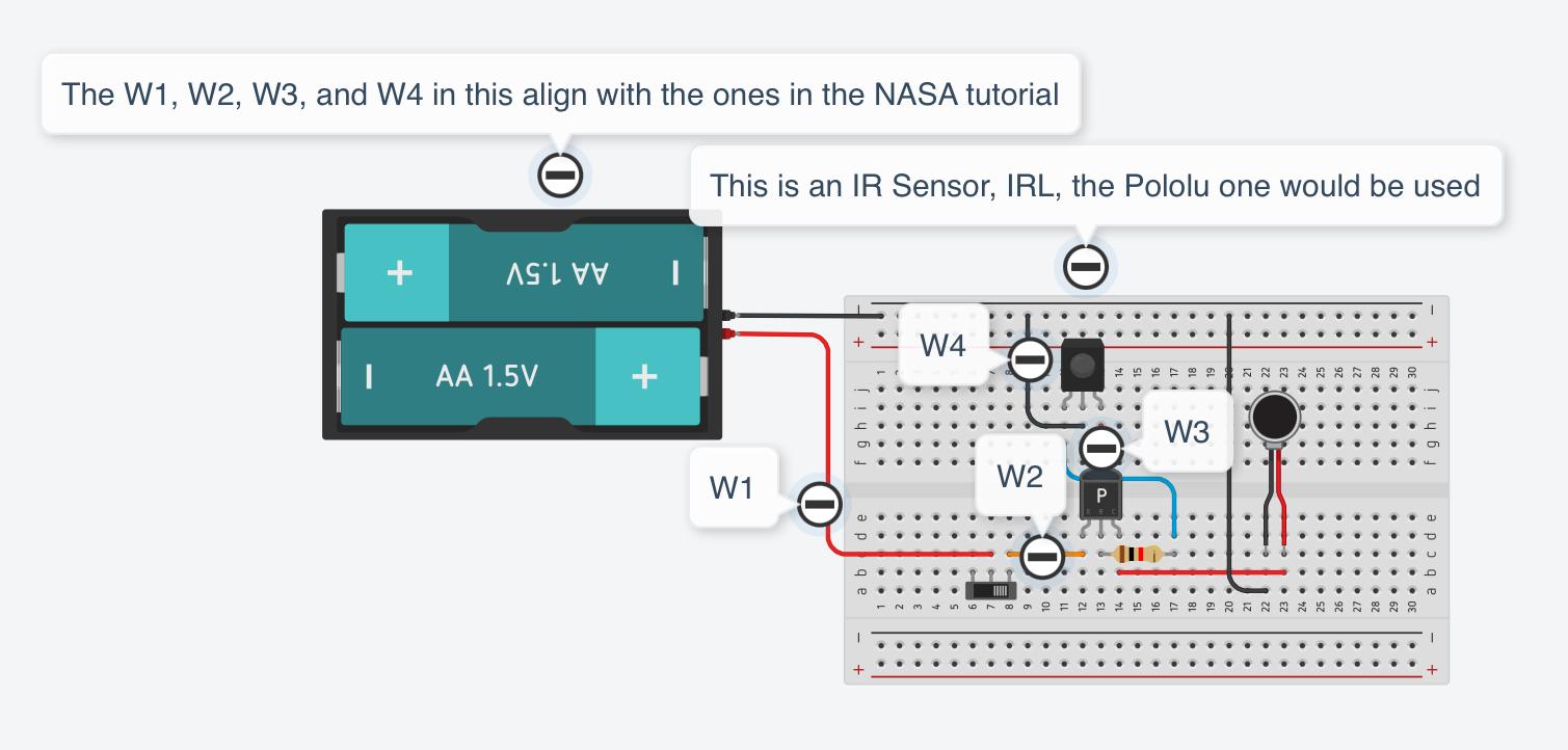
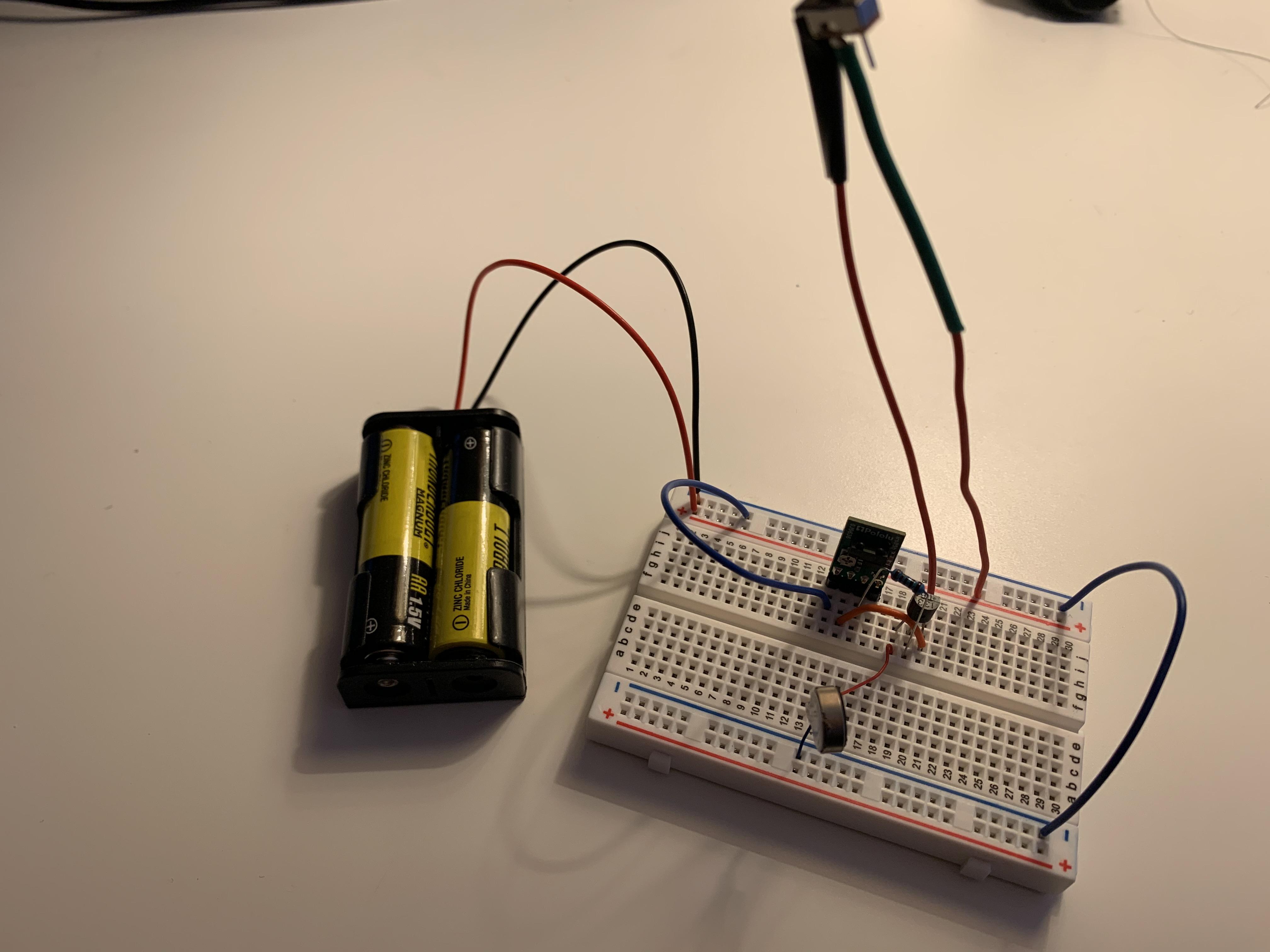
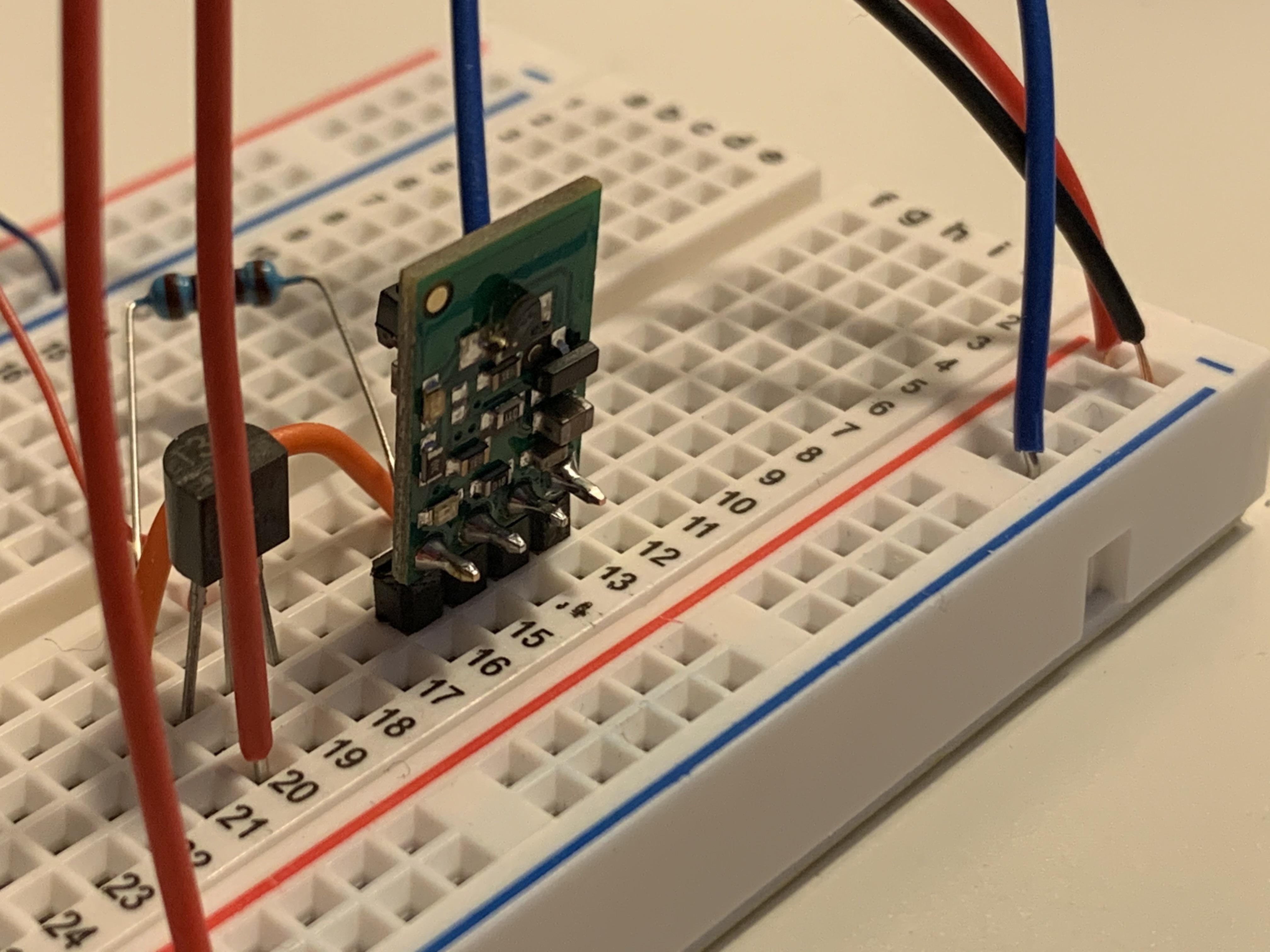
1) The first step in creating this project is to create the circuit on Tinkercad. While the original tutorial provides an electrical diagram, doing this allows you to visualize the circuit when assembling it with the breadboard
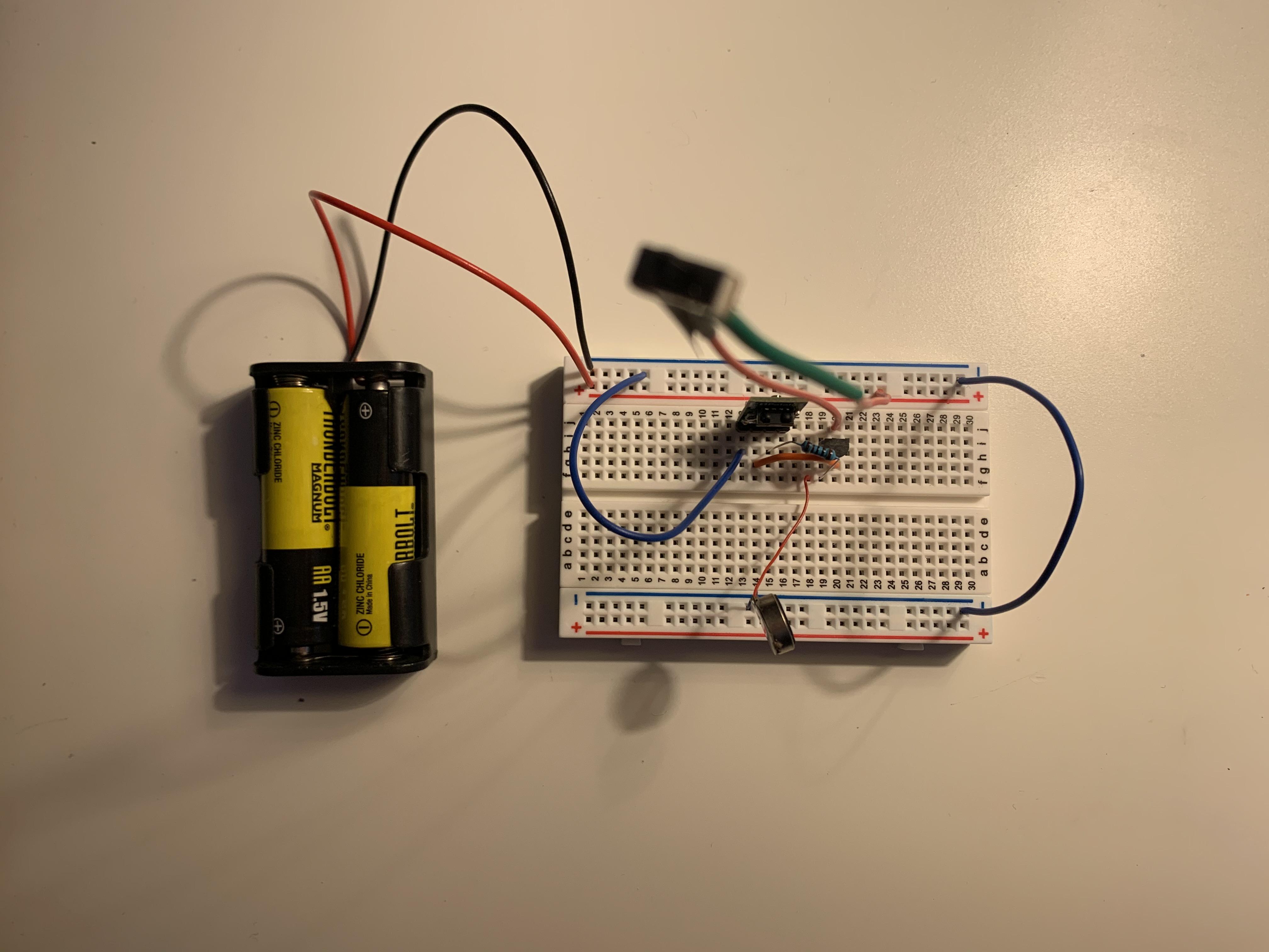
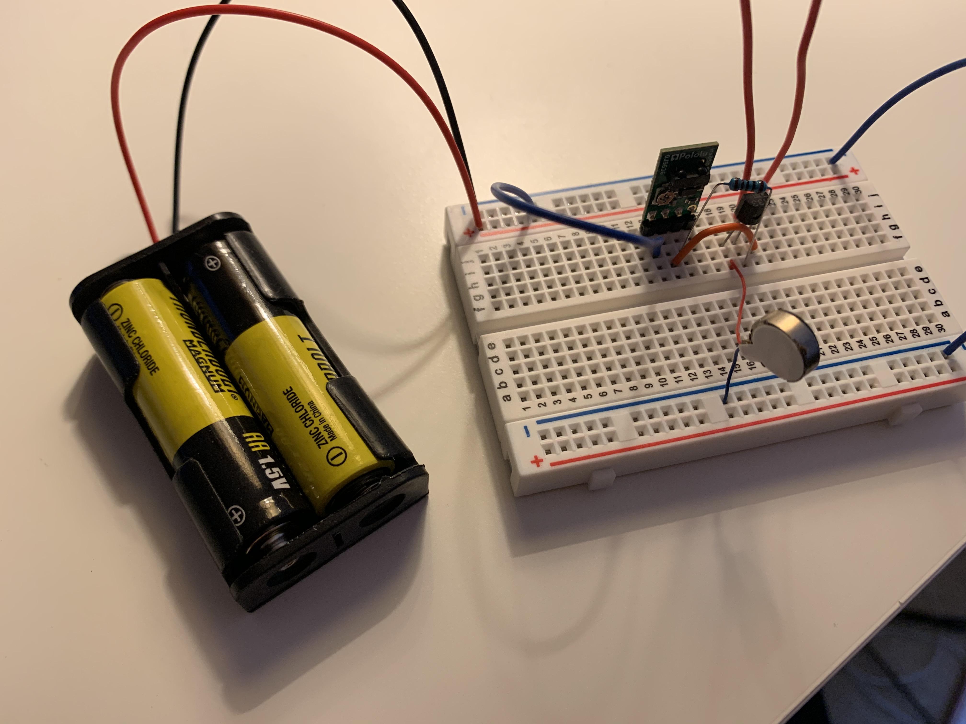
2) The next step is building and testing the circuit using the breadboard. Rather than going straight to soldering the piece together, taking this additional step can ensure that you will assemble it correctly. Having the circuit with the breadboard would also allow you to have a frame of reference for when you will solder the pieces together.
Designing the Bottom Pendant Piece
.jpeg)
.jpeg)
.jpeg)
.jpeg)
.jpeg)
3) Once you got the circuit to work, start making the pendant on Fusion 360 by using NASA's original design as a reference.
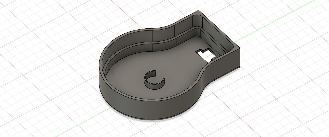
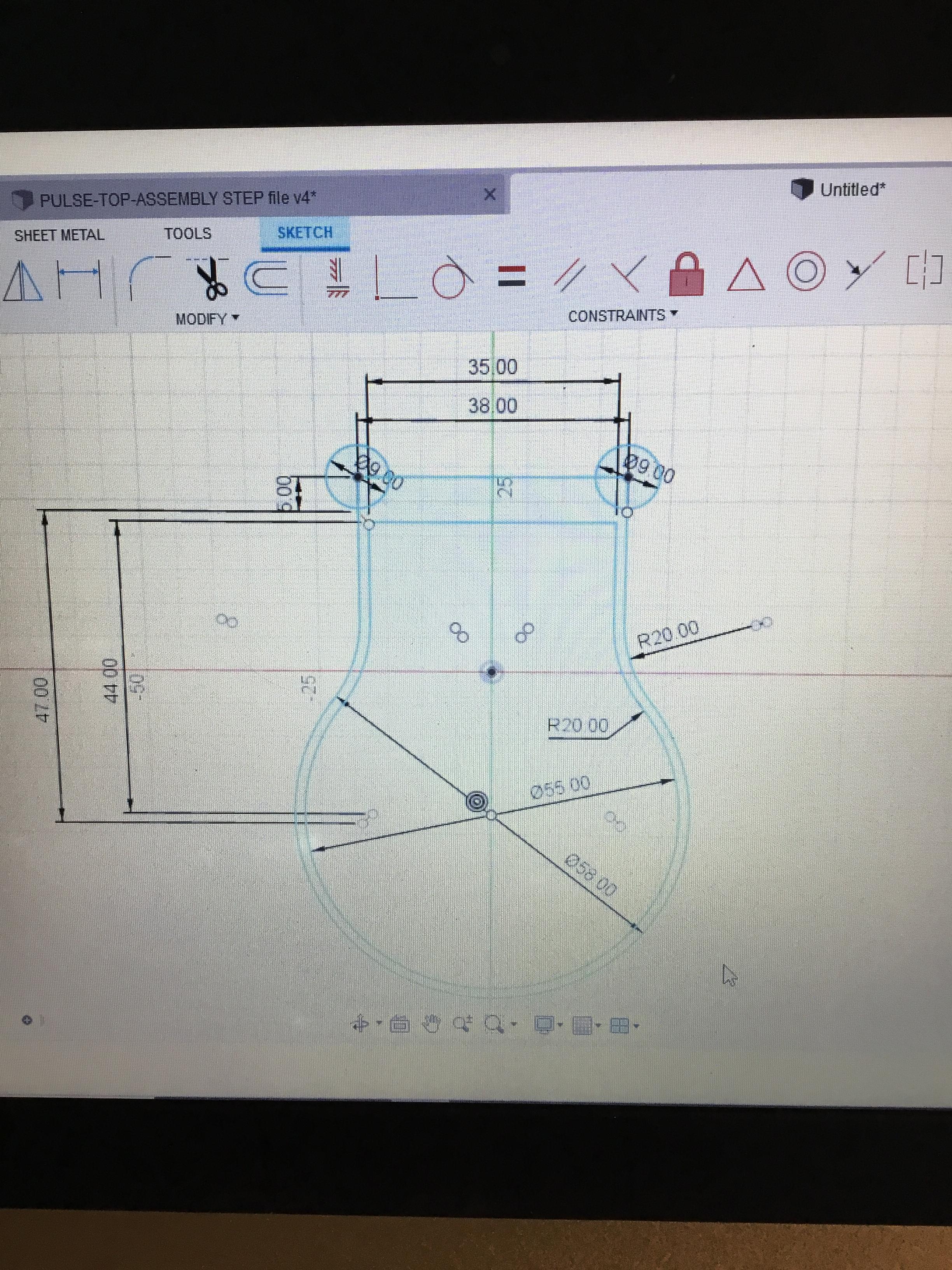
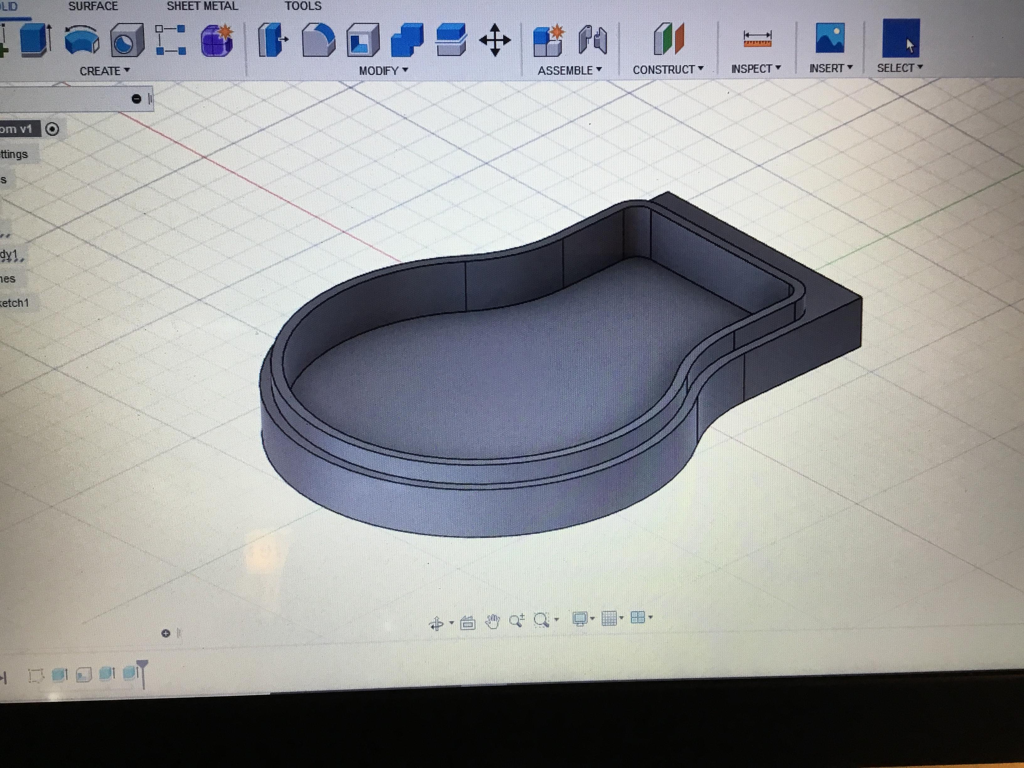
4) First, work on the bottom piece of the pendant. Start out by using the center diameter circle tool to draw a circle and the center rectangle tool to sketch a rectangle that was centered on the circle's rim. Then, use the trim tool on Fusion 360 to remove the inside pieces of where the rectangle and circle intersected.
5) Repeat step 4 to create another circle and rectangle so the circles were concentric and the rectangles were centered.
note: in the picture, I drew circles at each corner, but this is actually not necessary since you will not be needing these parts of the sketch at this step.
6) Then, use the fillet tool to round out the corners where the rectangle and the circle intersected. Fillet each side by 20mm. (All measurements in the picture on the left are in millimeters)
7) Once you have this basic sketch, extrude it. Extrude the interior part of the sketch by 10.5 mm and then use the shell tool to hollow the inside (I shelled it by 1.5mm). Then, extrude the outside part of the sketch by 7.5 mm.
8) Extruded the bottom of the pendant by 1.5 mm so that it will have a thicker base.
9) To create the opening for the necklace string, extrude the top face of the pendant by 5 mm
10) Then, on one side of the top part of the pendant, draw a center diameter circle with a 4 mm radius. After, extrude it so that it will create a hole through the other side.
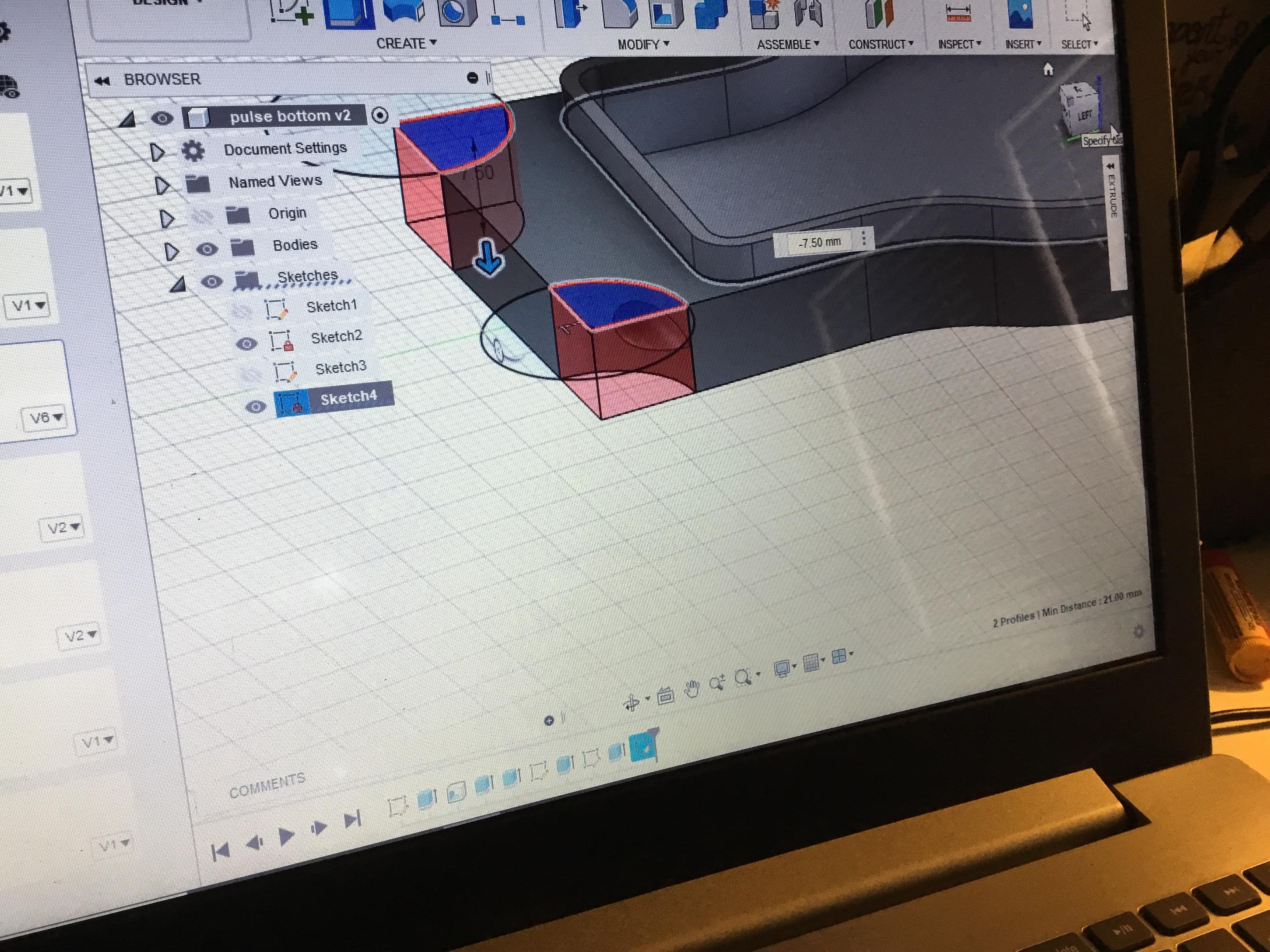
11) Next, sketch 17 mm radius circles centered at the top left and top right corners of the pendant.
12) Select each of these circles and extruded them by -7.5mm, which is the height of the outer part of the pendant.
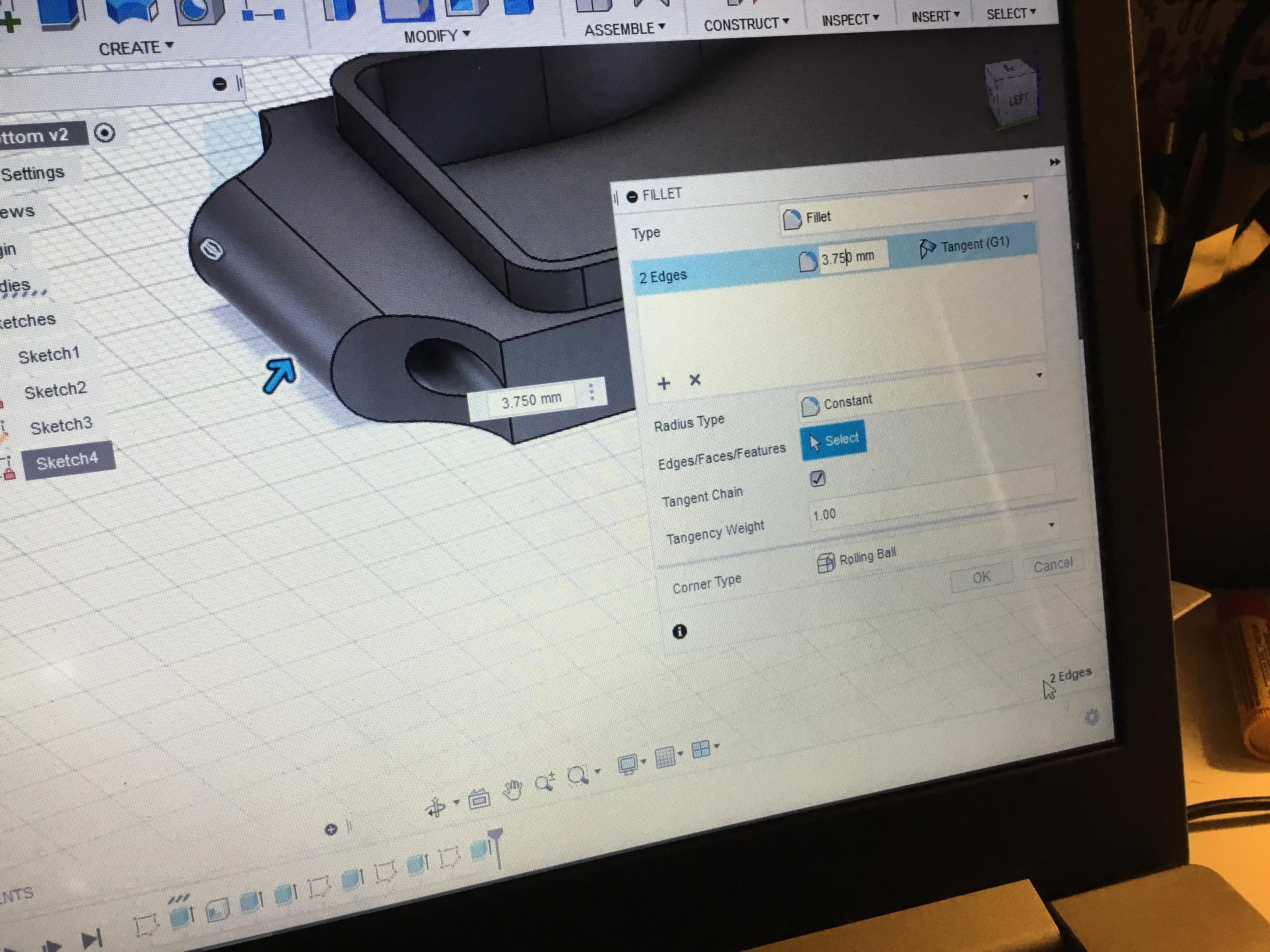
13) After, use the fillet tool to round the top edges of the pendant by 3.75mm and the bottom edges by 2.5mm. Also, fillet the upper corners of the pendant by 2.5 mm.
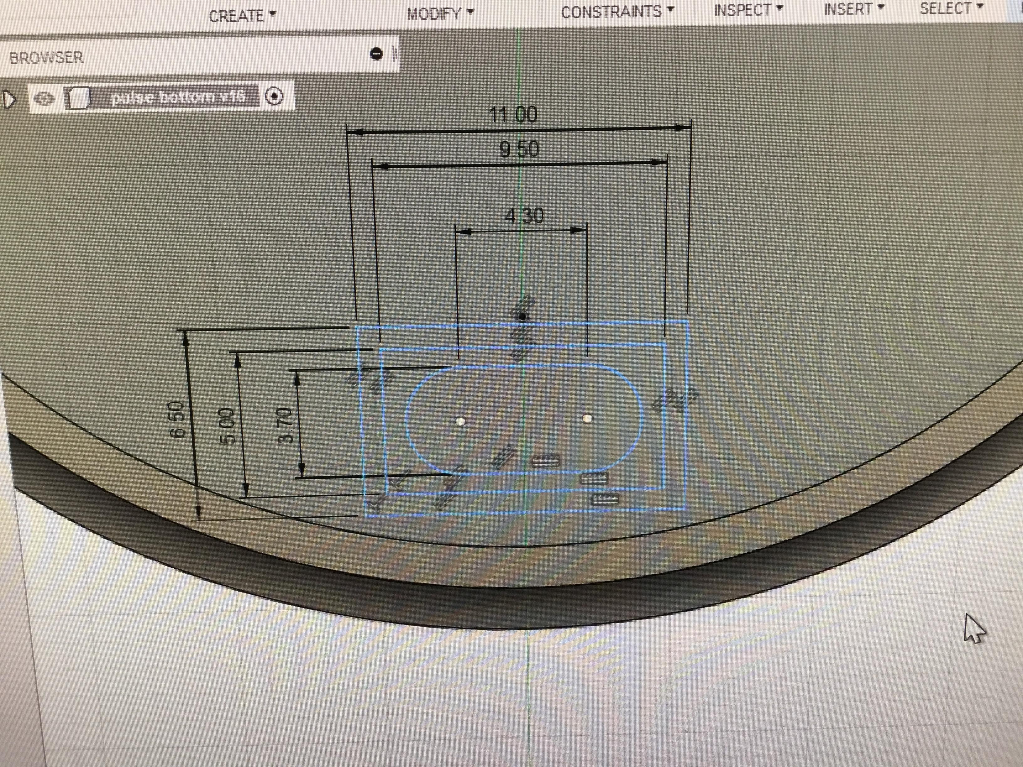
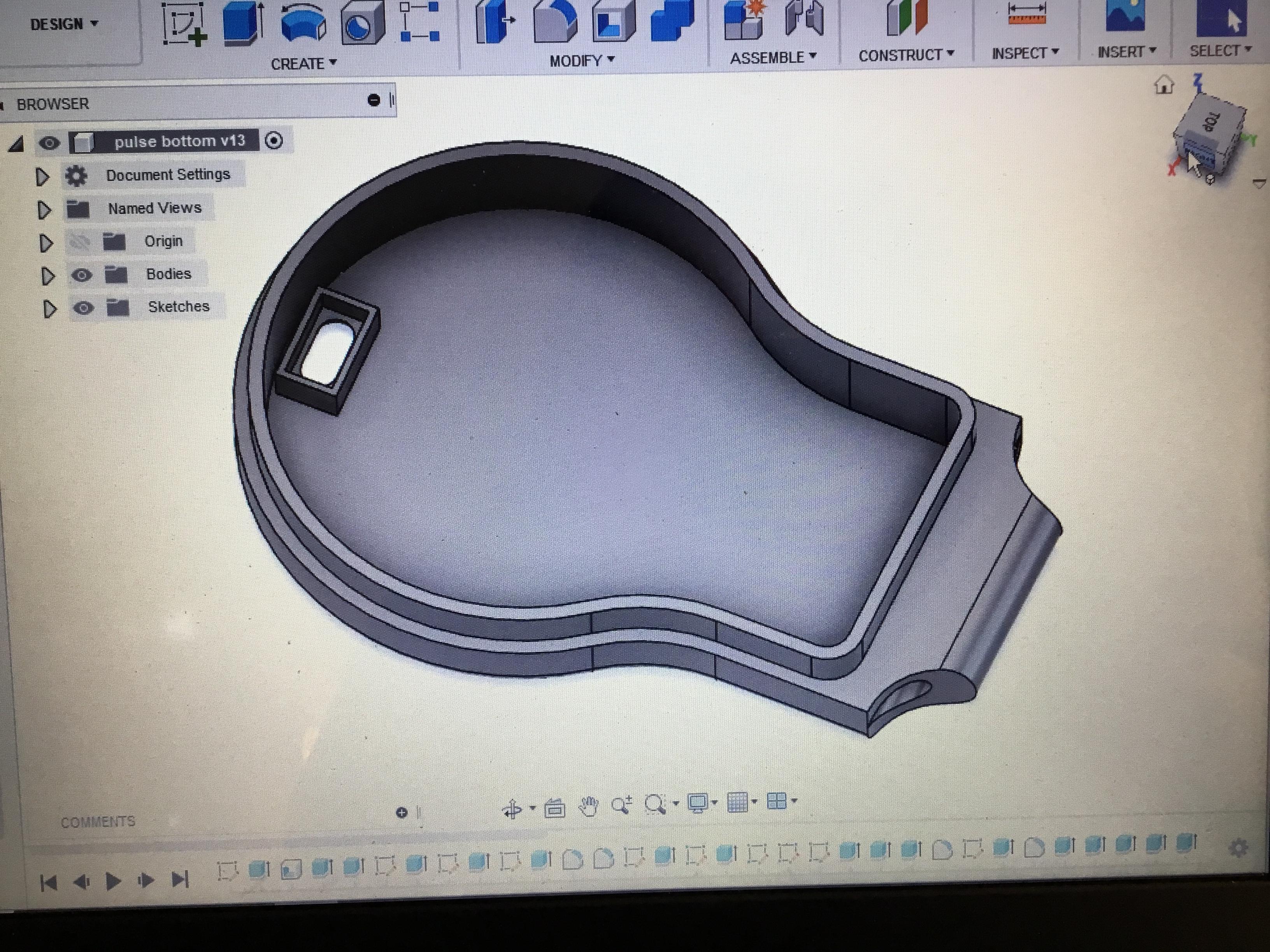
14) To create the compartment for the switch, create a new sketch with the inside of the pendant as the face and used the center rectangle tool to create a 6.5mm x 11mm rectangle centered at the bottom of the pendant and a 5mm x 9.5mm rectangle centered within that one.
15) Inside the smaller rectangle, draw a 3.7mm x 4.3mm rectangle and use the center diameter circle tool to create circles with a radius of 1.85mm on either side of the rectangle. Afterward, use the trim tool to cut out the excess parts of the rectangle and circle. The fourth picture on the left shows how the sketch should look.
16) In the part that is shaped like an ellipse, extrude it by -3 mm so that it will cut a hole through the bottom of the pendant.
17) In the outline of the rectangle, I extrude it up by 4 mm. Also filleted the opening of the slide compartment by 3 mm.
Designing the Top Pendant Piece
.jpeg)
.jpeg)
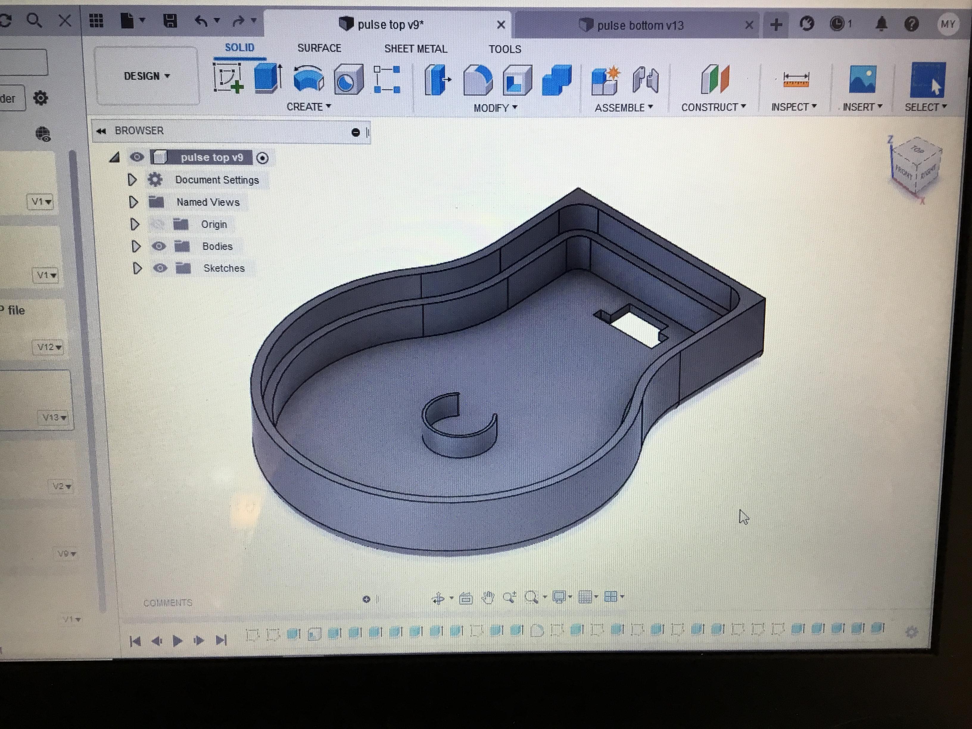
18) Next, repeat steps 1-6 to begin creating the top part of the pendant.
19) Then extrude the outer part of the pendant by and 17.5 the inner part of it by 8.5.
20) Now repeat steps 7-8 and 13.
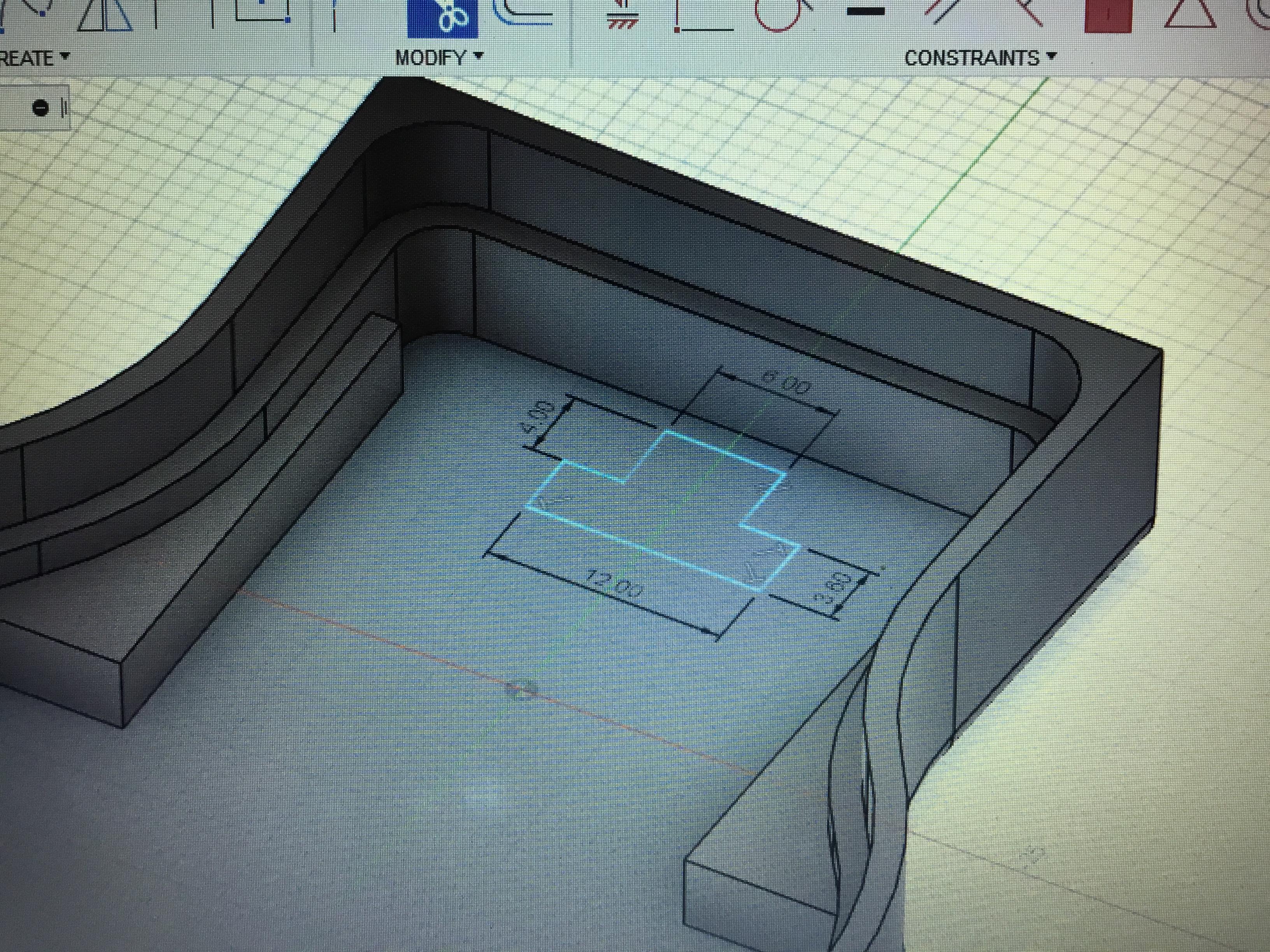
21) To create the opening for the sensor, use the sketch tool and selected the bottom face of the top piece. Then, selecting the center rectangle tool, sketch a 4 mm tall, 6mm wide rectangle centered at the top of the bottom face of the pendant (see the first picture on the left for reference).
22) Directly below it, sketch a 3.6 mm tall, 12 mm wide rectangle using the center rectangle tool.
23) Once you have finished this sketch, select the shape and extrude it by -3.00 mm.
24) After extruding this part, go back into the sketch by right-clicking on it and selecting edit sketch.
25) Staying in the same sketch, use the center diameter circle tool to draw two concentric circles at approximately the middle of the pendant. The circles have diameters of 10.1 and 11.1 respectively.
26) Next, draw another center diameter circle centered at the top of the larger circle. The measurements of this circle do not matter, as long as it's large enough to let the wires of the buzzer through and small enough to maintain the shape of the other two circles as to hold the buzzer. For your reference, the radius of the circle I created was 4.5mm.
27) Then, use the trim tool to remove the excess parts of the circles and to achieve the desired "C" shape.
3D Printing
.jpeg)
.jpeg)
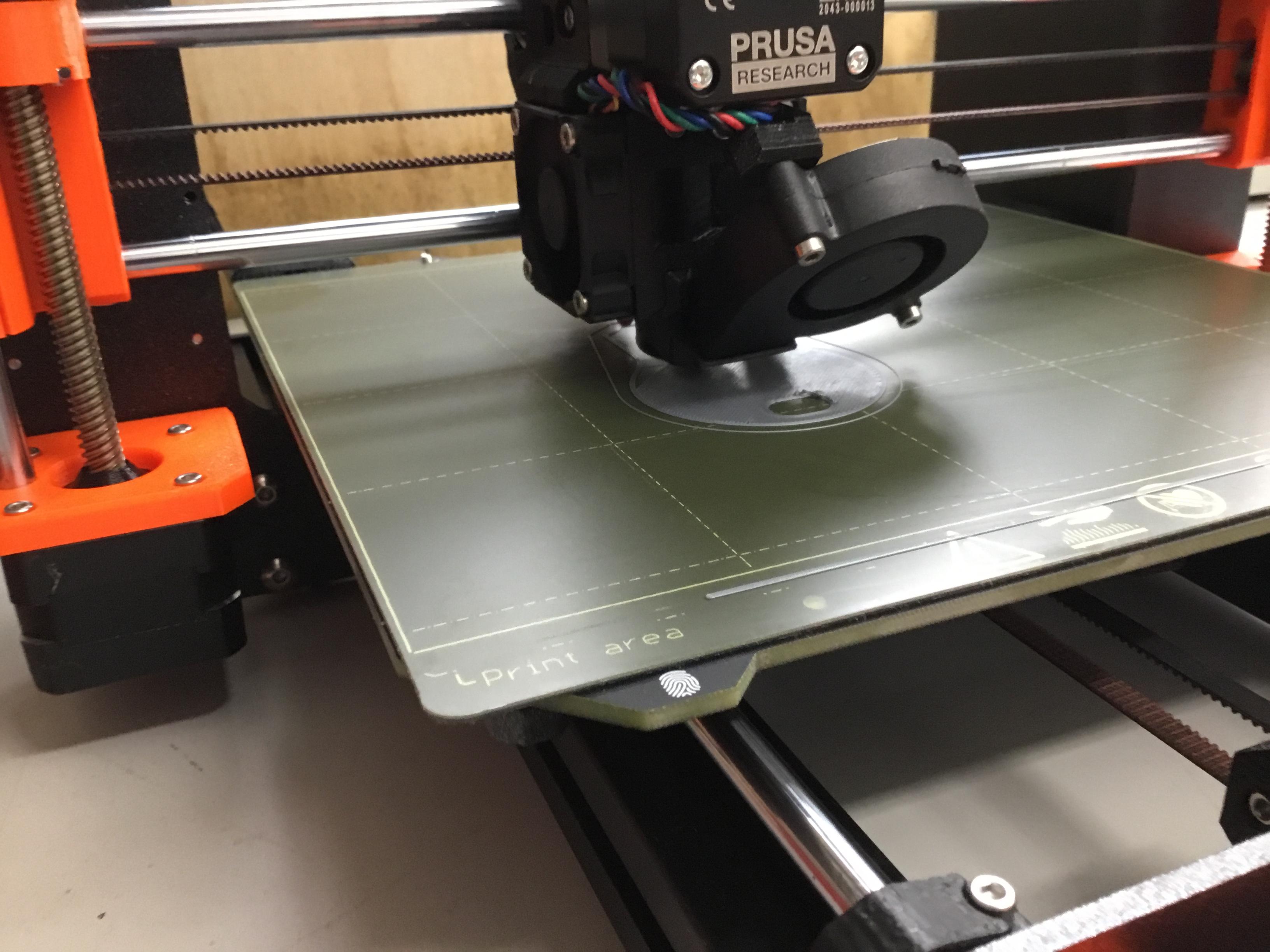
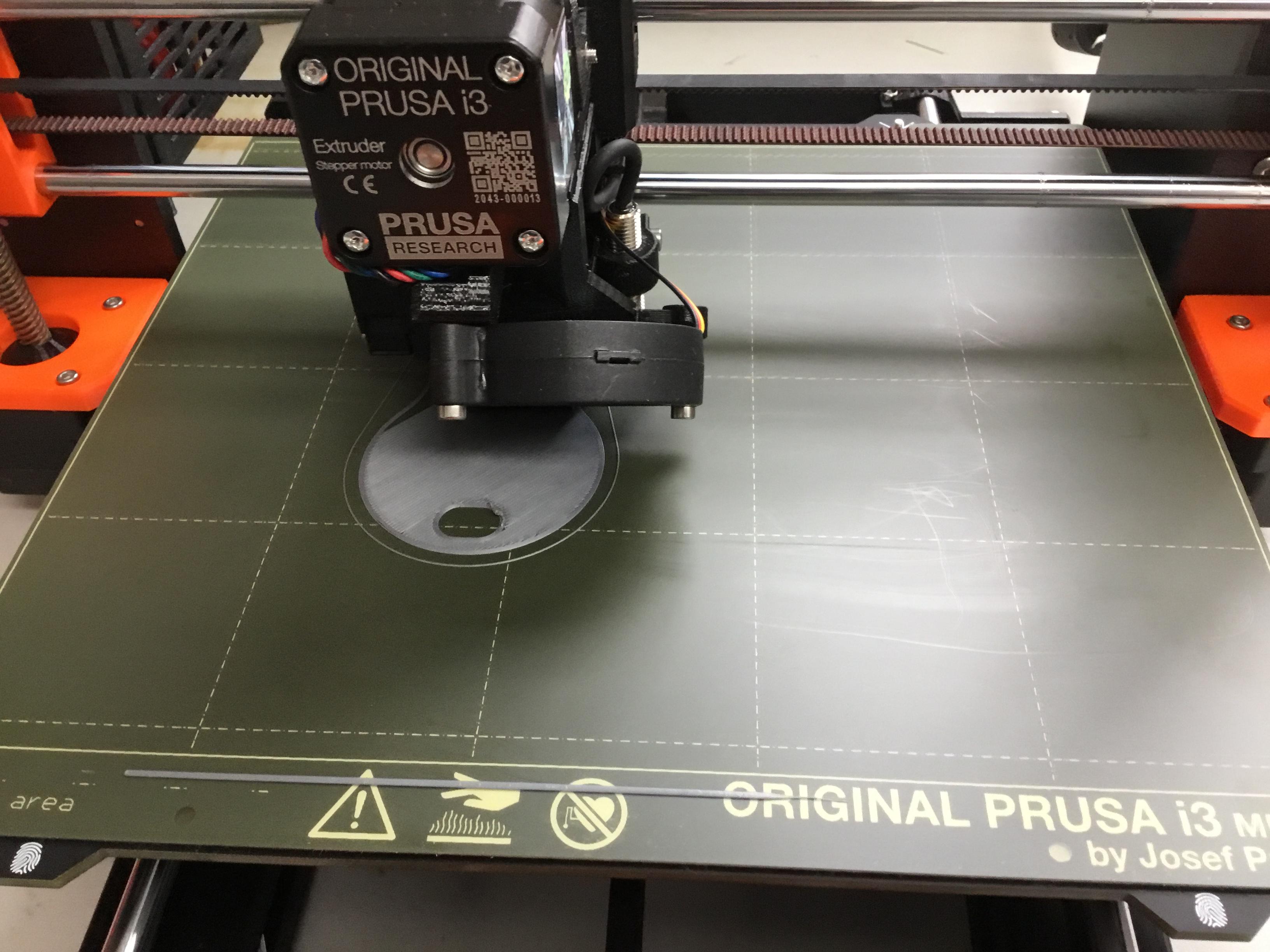
28) Once you are satisfied with the pendant, 3D print it. You can use whatever 3D printer and printing program you have, but I personally used the Prusa printers.
29) In Fusion 360, go to "file," and select "3D print." Do not use Fusion 360 to send the project to a local printer.
30) After pressing "ok" and saving each file as an STL file, move over to the PrusaSlicer program.
31) Import one file into the PrusaSlicer program and selected the 0.15mm option for printing. Then, press "create G-Code."
32) Using the G-Code files for the top and bottom pieces, print the two pieces.
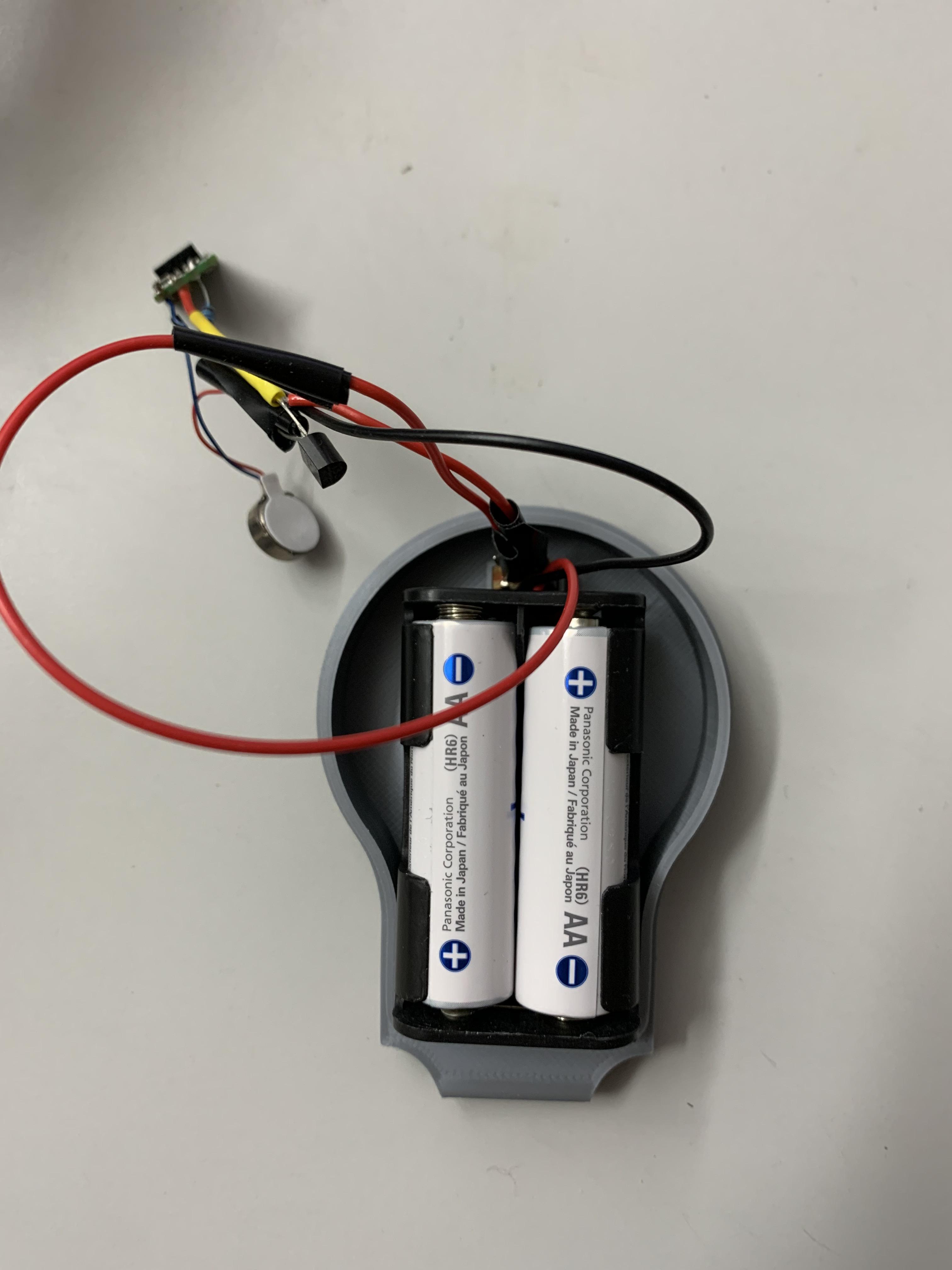
33) Once you get the circuit to fit into the pendant as desired and have added the string to make the pendant into a necklace, you are finished!
Previewing the Pendants
Here's how each piece of the pendant should look!
Project Demonstration

Here is a video of how the pendant should work!