Mycroft Mark II Developer Kit Assembly
by oojoshua in Circuits > Raspberry Pi
6807 Views, 24 Favorites, 0 Comments
Mycroft Mark II Developer Kit Assembly
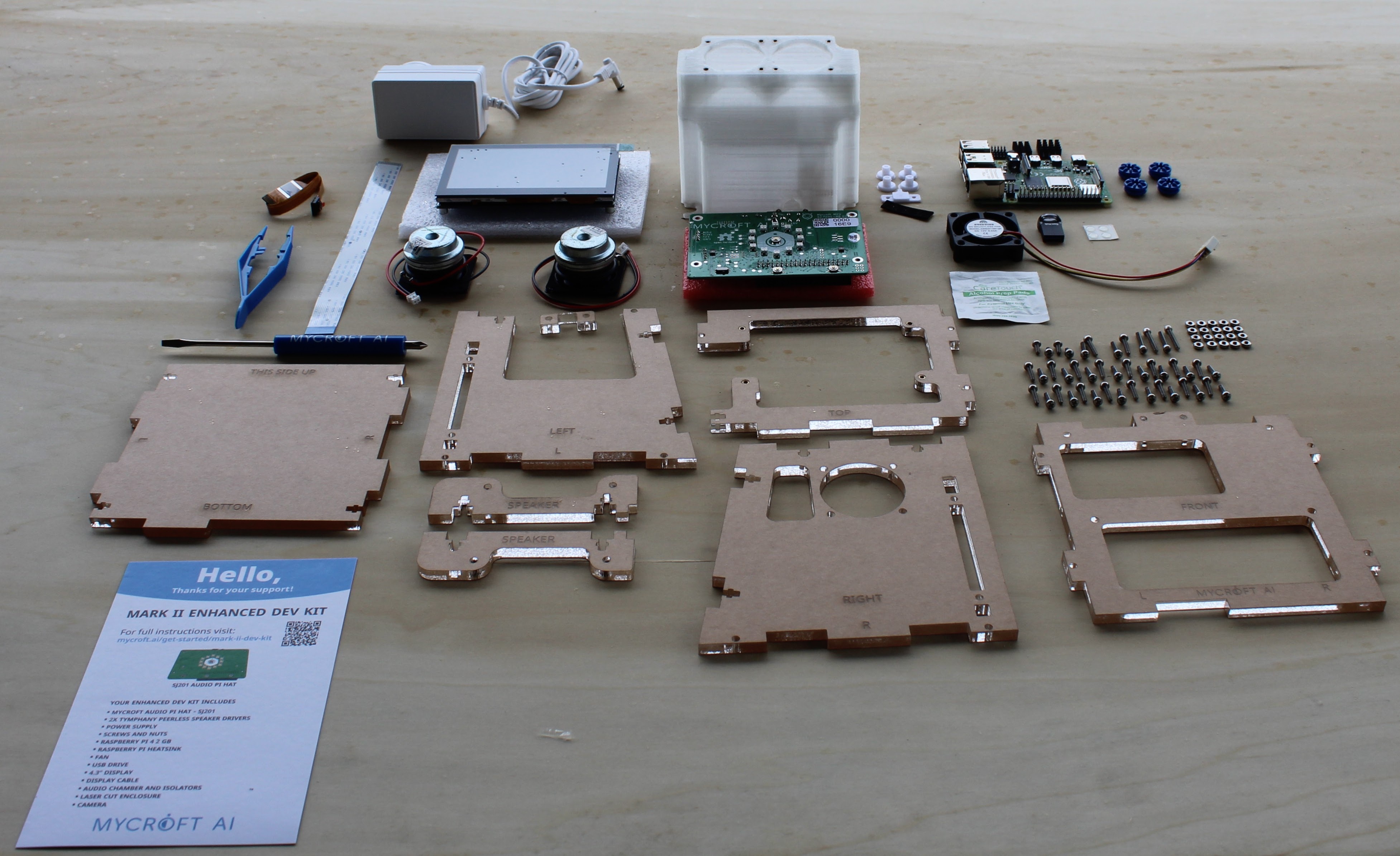
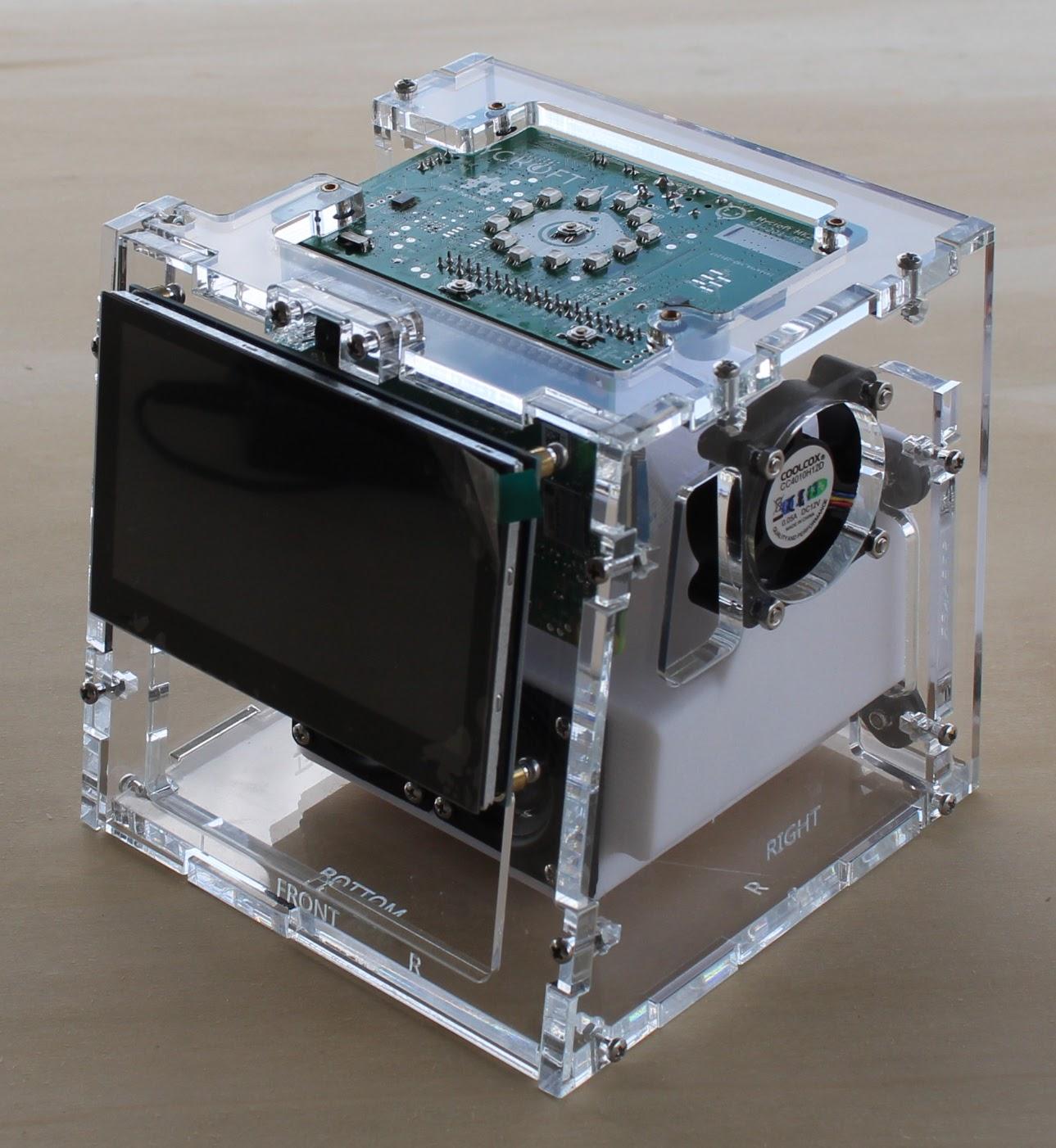
These are instructions for assembling a Mycroft Mark II Developer Kit.
BEFORE YOU START:
Download this image to your desktop/laptop computer.
If you don't have an enhanced developer kit from Mycroft and need files to cut and 3D print, you can find them in our hardware Github repository.
Supplies
The kit should contain:
1x audio Chamber
32x 2.5mm x 10mm stainless steel panhead screws
4x 2.5mm x 6mm stainless steel panhead screws
4x 2.5mm x 12mm stainless steel panhead screws
4x 3mm x 16mm stainless steel panhead screws
16x 2.5mm thin profile stainless steel nuts
4x 3mm stainless steel nuts
4x vibration damping grommets
4x vibration damping inserts
4x vibration damping gaskets ( 2.5mm inner diameter )
4x clear adhesive pads
2x speaker drivers
1x cable retaining clip
1x USB flash drive
1x 4" touchscreen
1x display cable
1x camera module
1x 40mm cooling fan
3x heat sinks
1x SJ201 printed circuit board
4x vibration damping
1x Raspberry Pi
1x alcohol wipe
1x left side acrylic cutout
1x right side acrylic cutout
1x bottom acrylic cutout
1x top acrylic cutout
1x front acrylic cutout
2x speaker mounting tab acrylic cutouts
1x camera alignment acrylic cutout
1x phillips head screwdriver
1x tweezers
1x 12v power supply
Apply Vibration Dampers to the Top of the SJ201 PCB
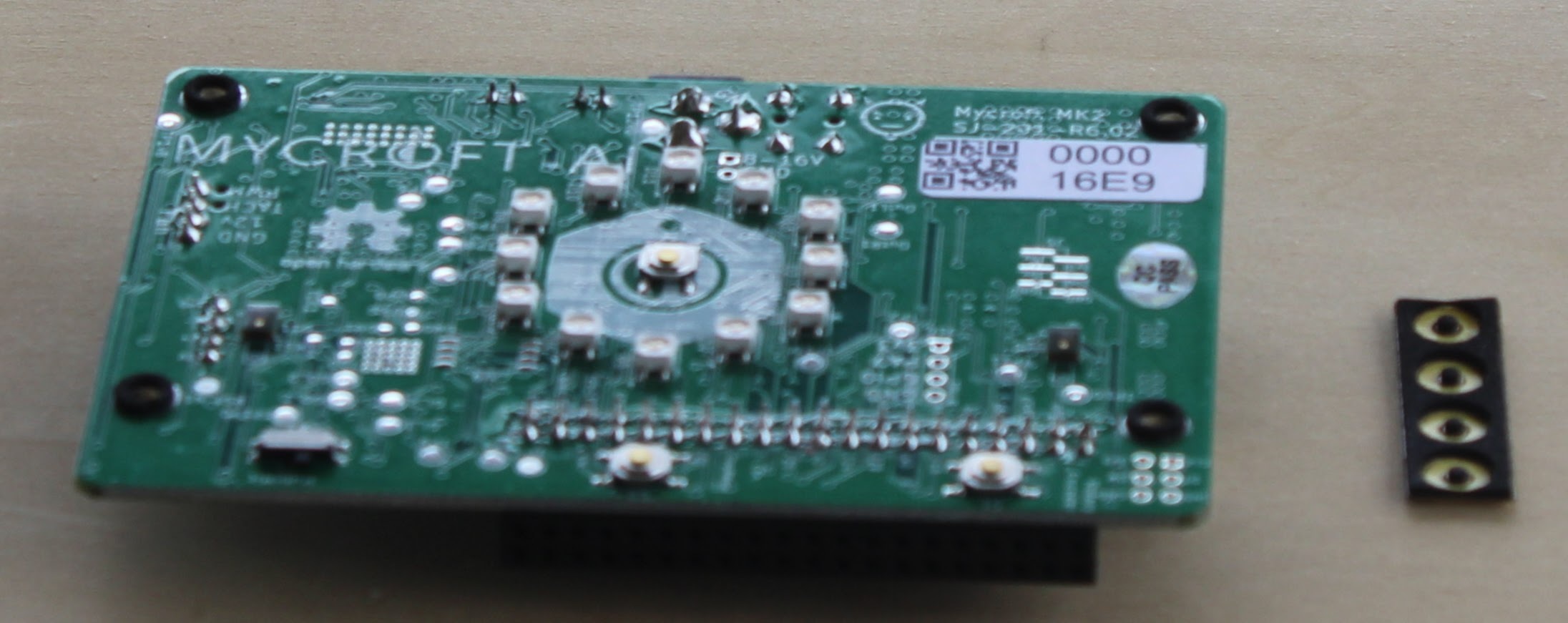
With the Simon Jester board upright, apply the vibration dampers to the top of the printed circuit board.
Attach SJ201 to the Bottom Side of the Cut Acrylic Top
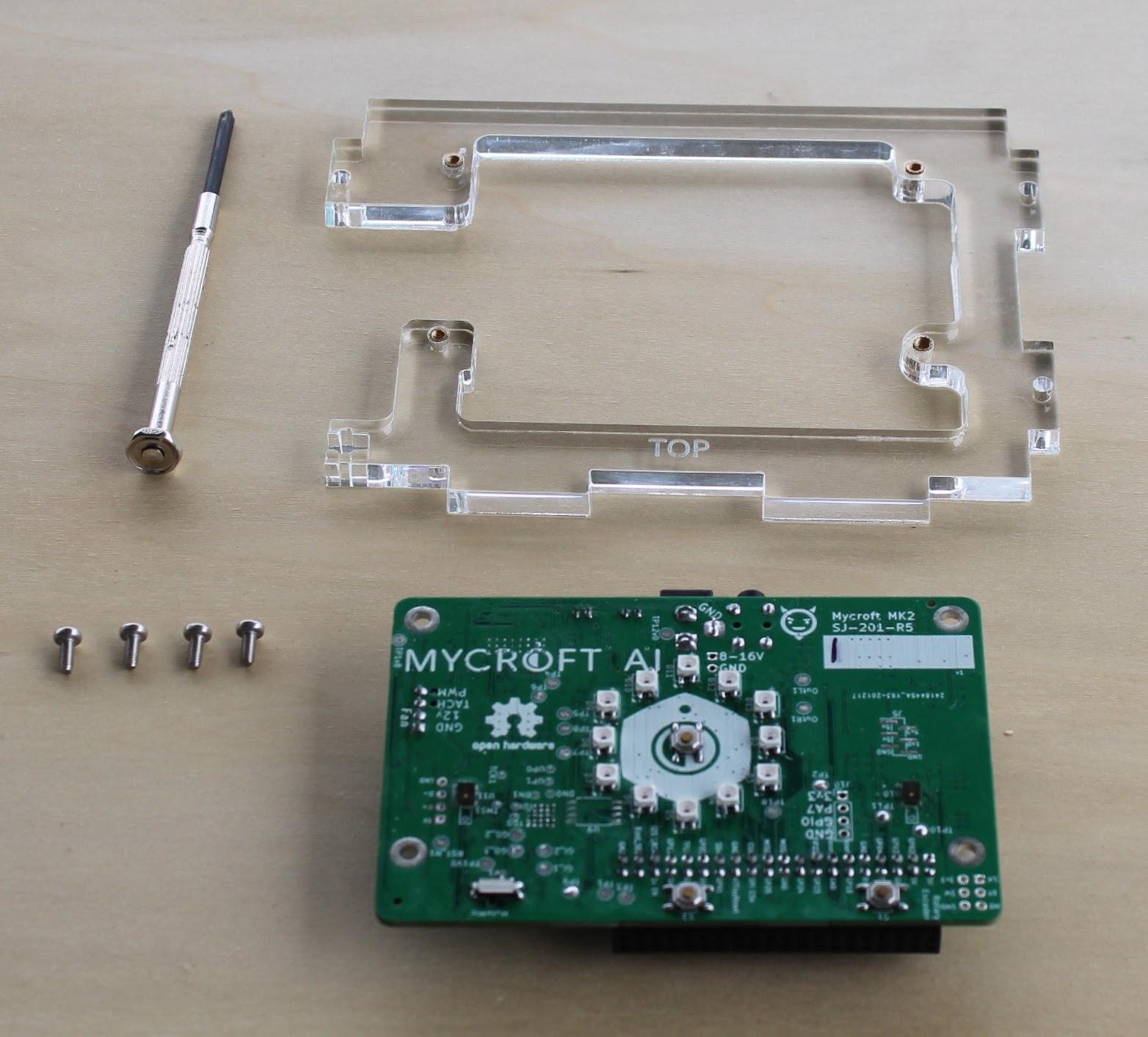
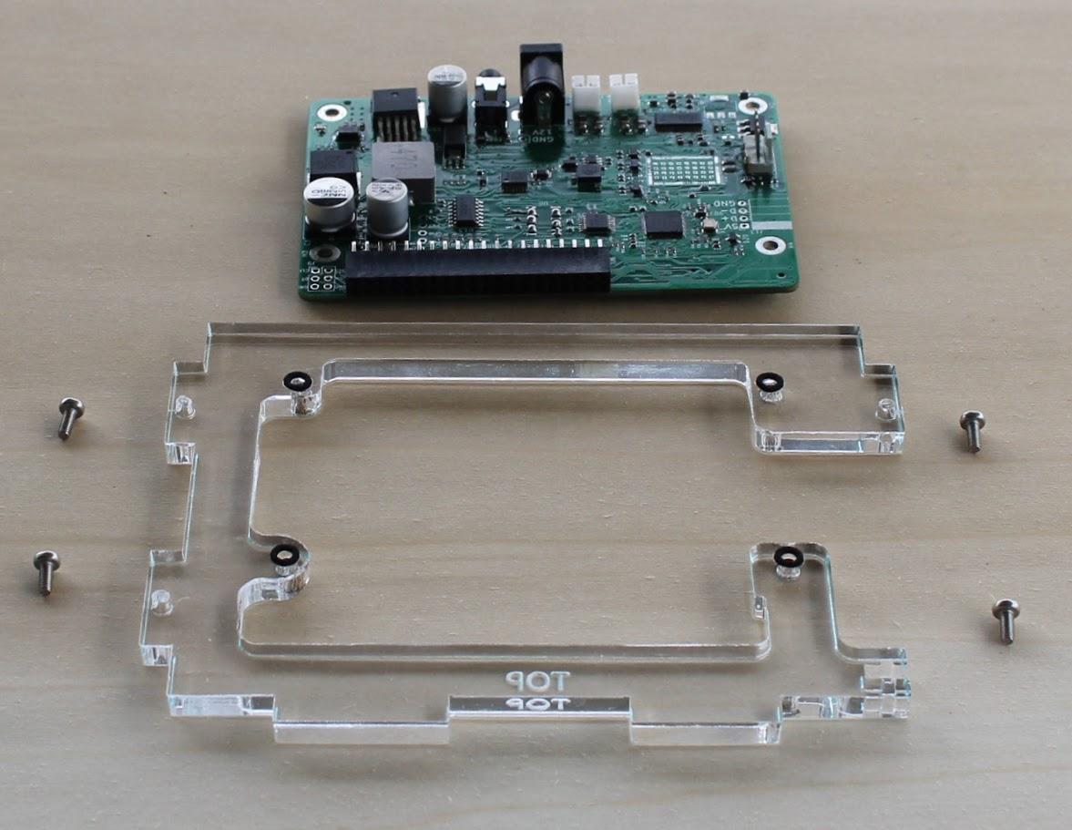
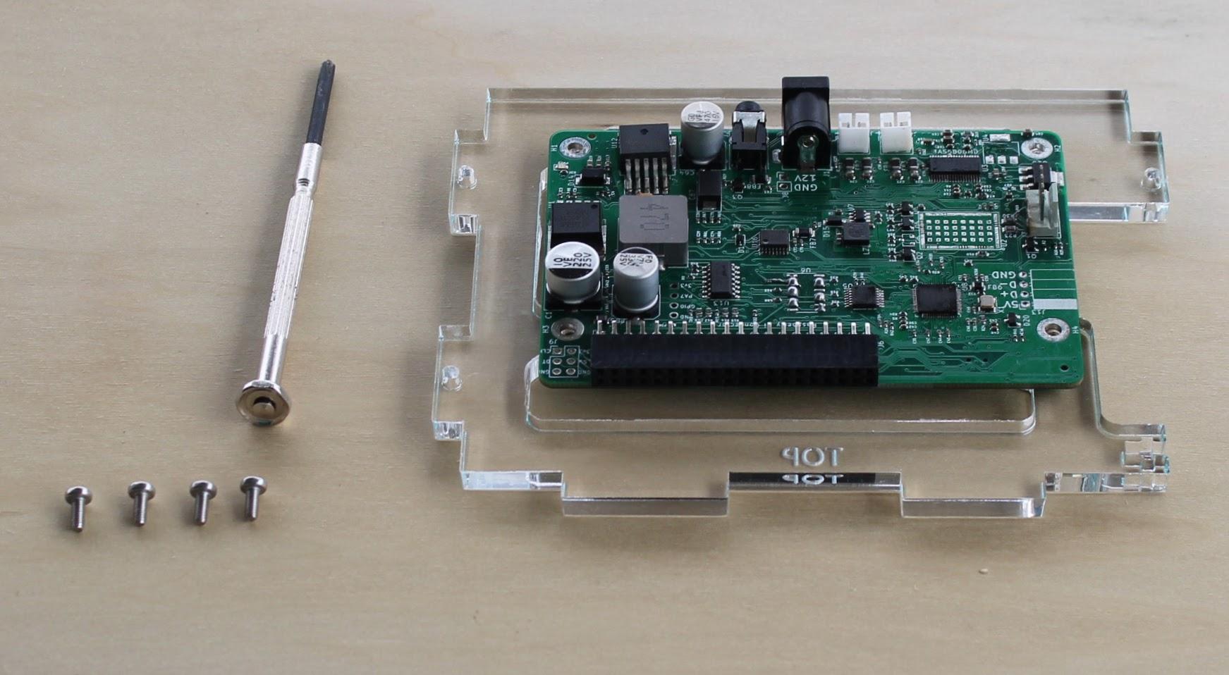
First add the small vibration isolation gaskets to the bottom side of the acrylic cut top.
Next align the SJ201 to the bottom of the cut acrylic top.
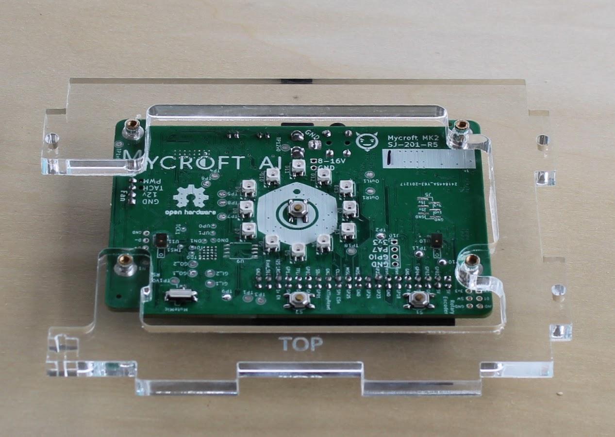
Insert 4x 2.5mm x 6mm stainless steel screws to secure the SJ201 in place.
When you are finished the SJ201 should be mounted to the bottom of the cut acrylic as shown.
Assemble the Speaker Enclosure
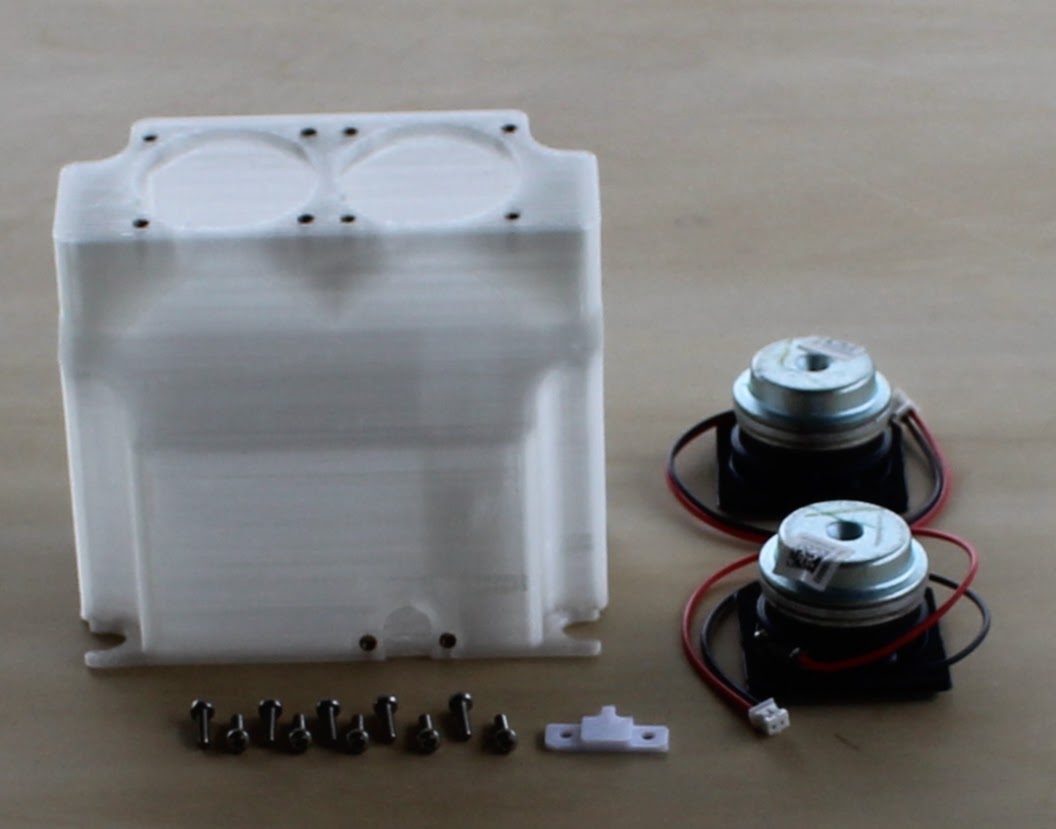
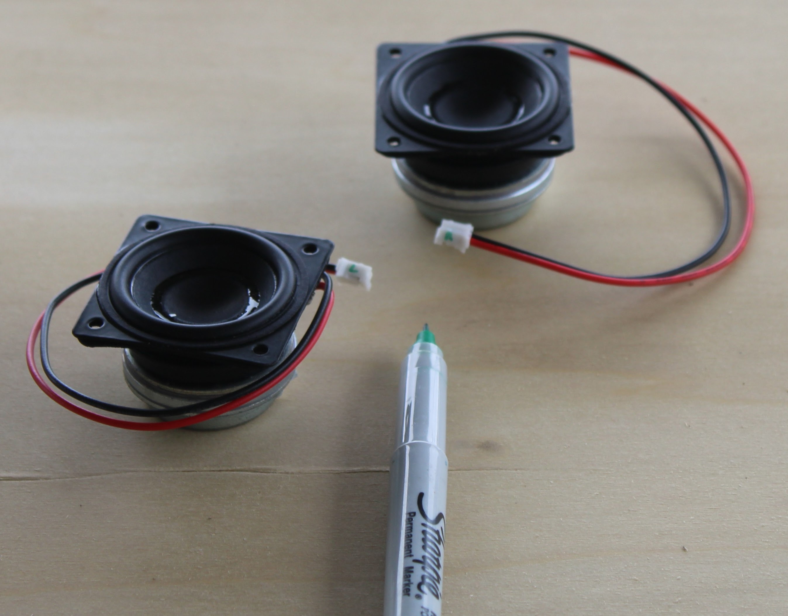
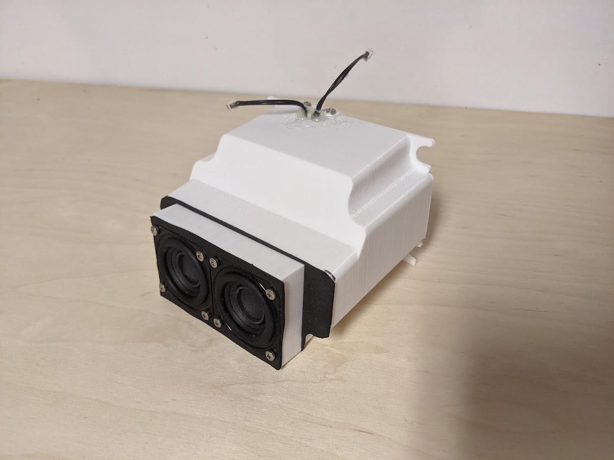
It is helpful to label the speaker wires "left" and "right" using a small permanent marker.
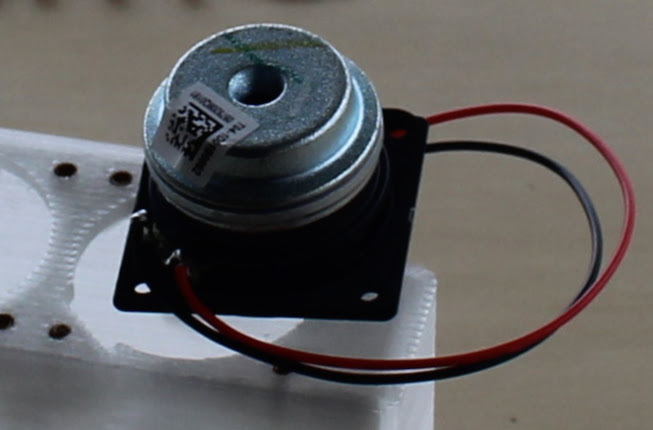
The small slots in the speaker enclosure are intended to allow the soldered speaker connectors to pass through the hole. Align the speakers so that the solder joints pass through the hole.
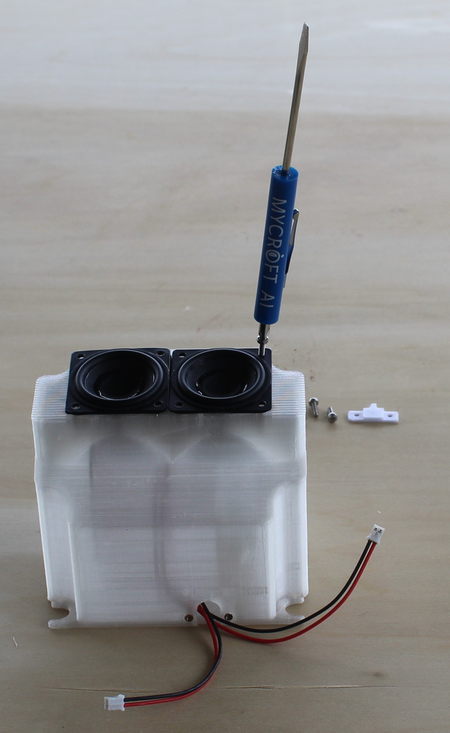
Insert the speaker drivers into the audio chamber and fish the wires through the speaker wire hole.
Secure the speakers with 8x 2.5mm x 10mm stainless steel pan head screws.
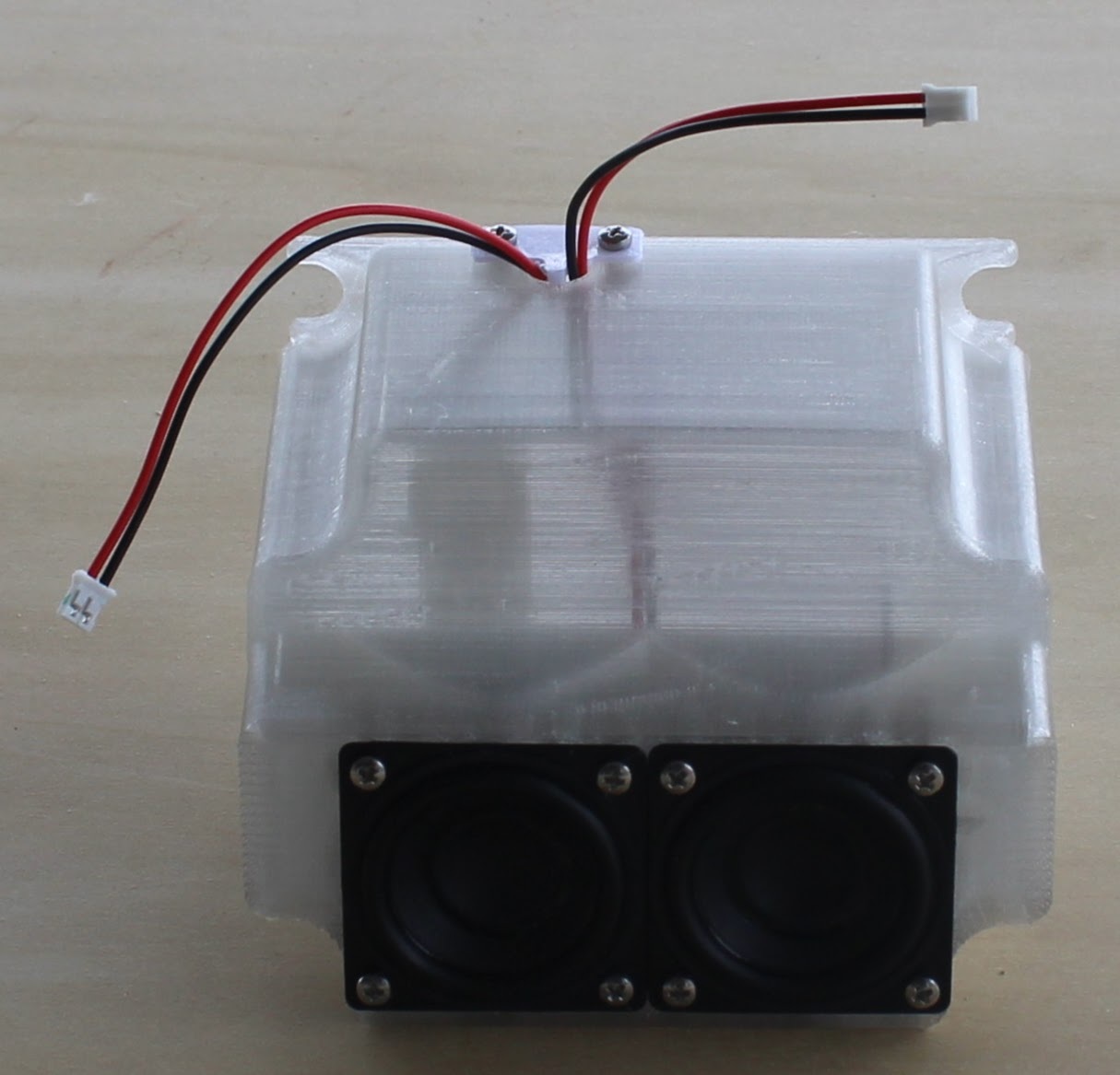
Add the speaker holder clip and secure the clip to the speaker wire hole making sure that one wire runs on either side of the clip's tab.
Secure the speaker holder clip with 2x 2.5mm x 10mm stainless steel pan head screws.
If you received a Dev Kit after August 23, 2021 it will come with a 3D printed adapter and two gaskets to assemble on the front of the speaker enclosure. The reason for the adapter is that the speaker drivers are from a different manufacturer and the fit is very tight in the original speaker enclosure. Apply the adhesive backed gasket to the face of the speaker enclosure. Apply the other gasket to the face of the adapter. The goal is to create a sealed envelope for the speaker enclosure. Next secure the speakers with longer 8x 2.5mm x 20mm screws. The screws will go through the adapter and into the threaded inserts on the speaker enclosure.
NOTE: If you have a hot glue gun you can use a small dab of hot glue to seal the wires to the tab. This makes the audio chamber air tight and may ( slightly ) improve sound quality.
Attach Fan and Both Left and Right Speaker Mounting Tabs
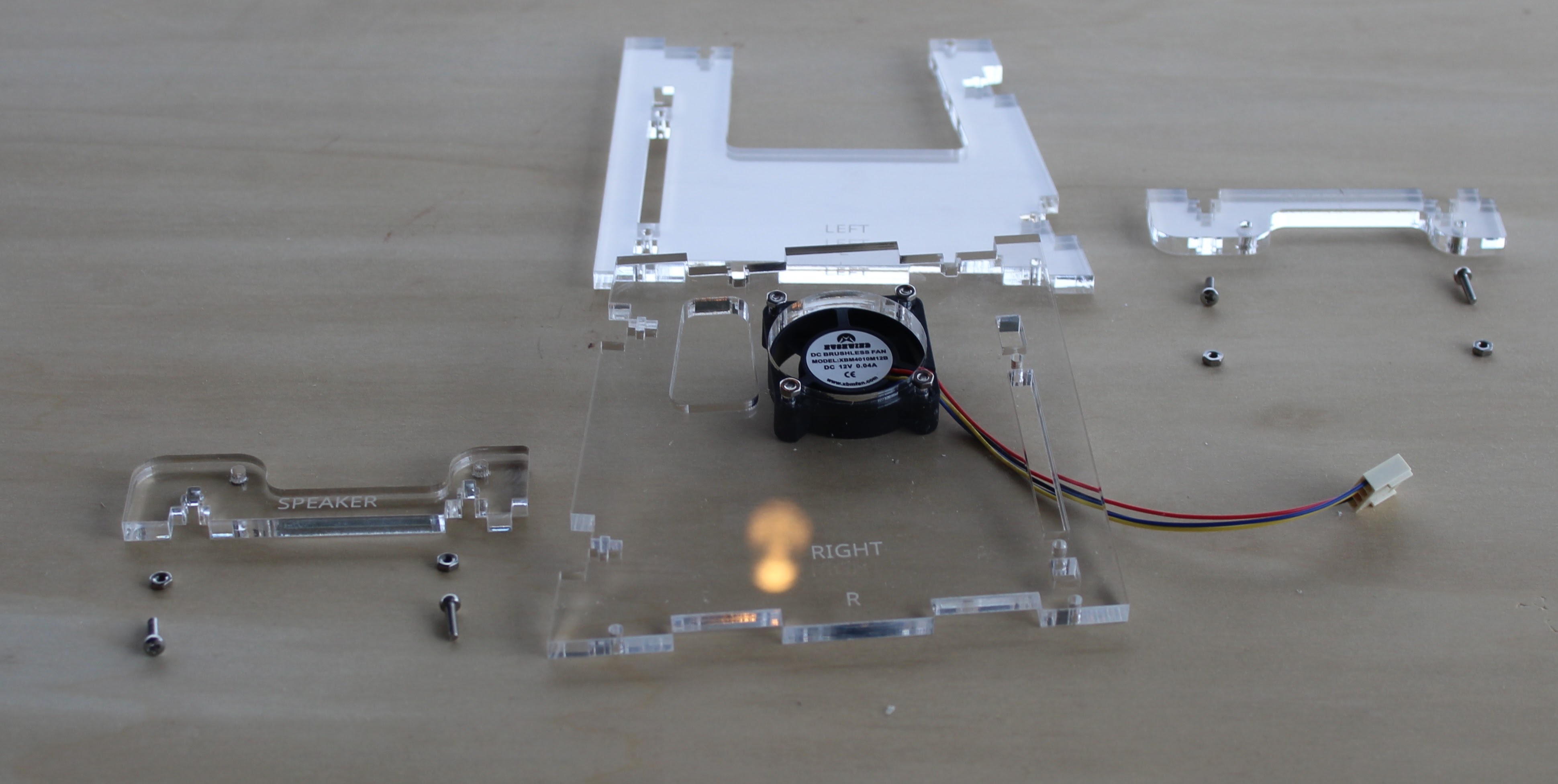
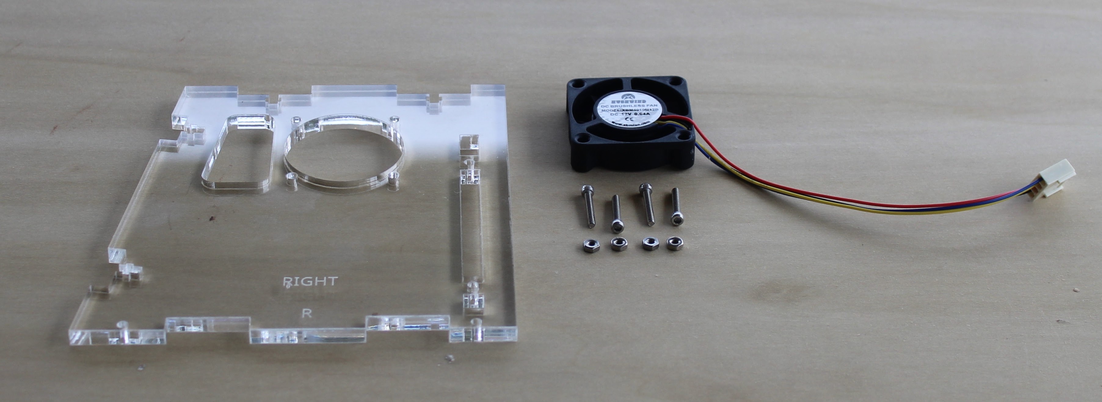
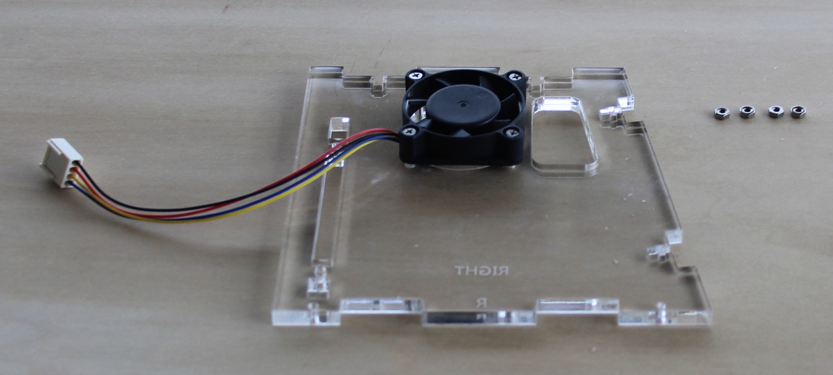
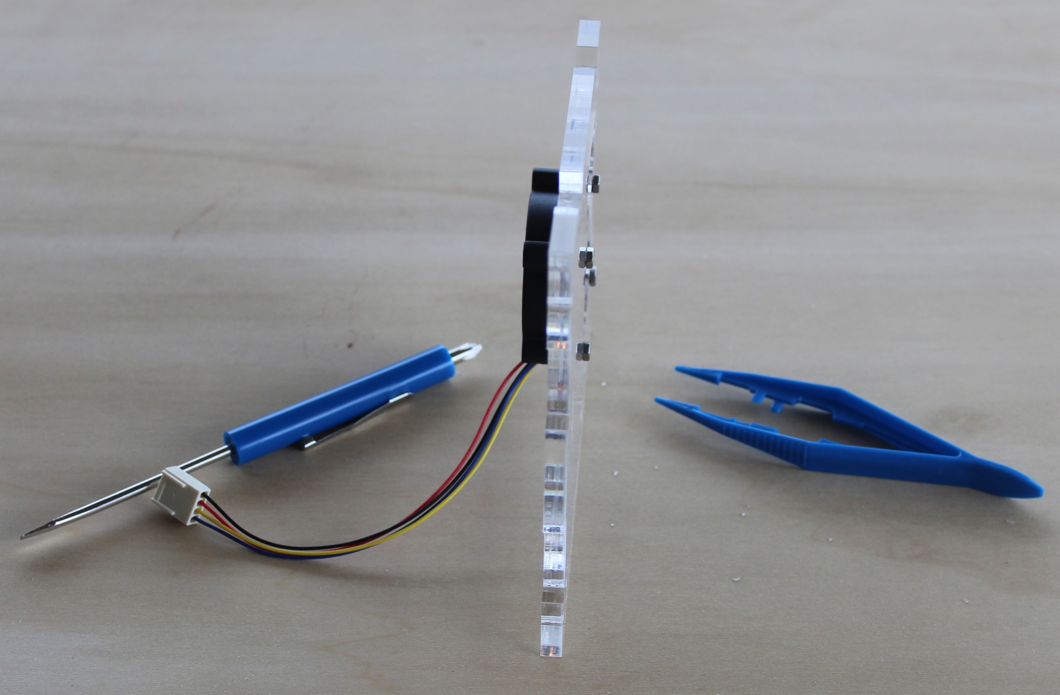
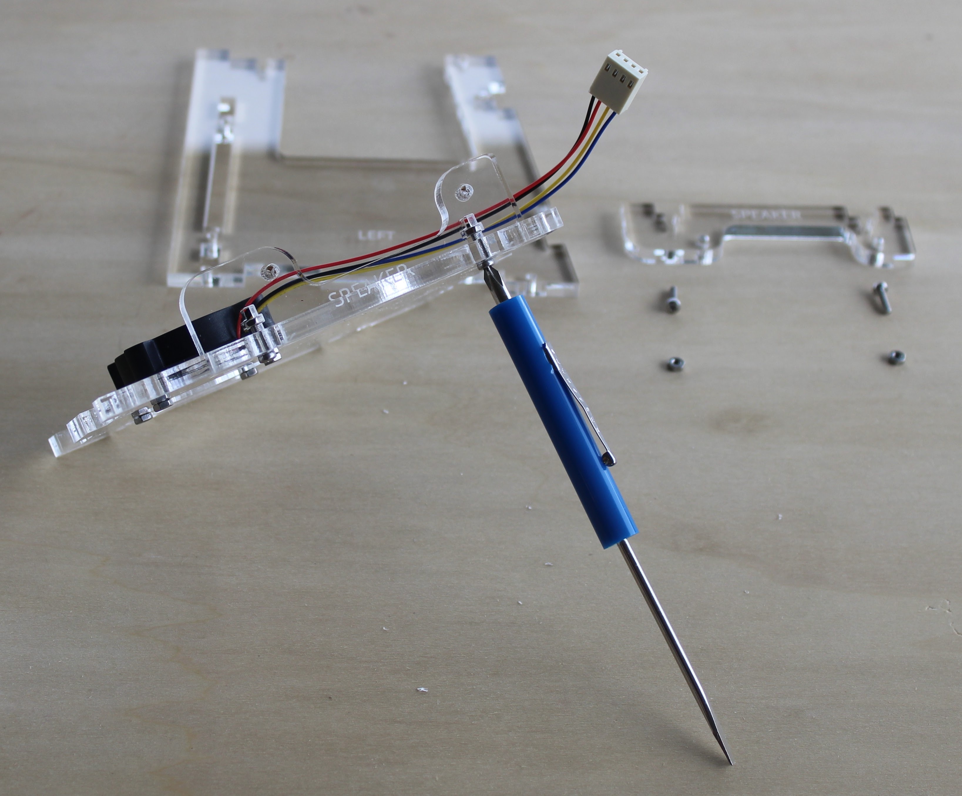
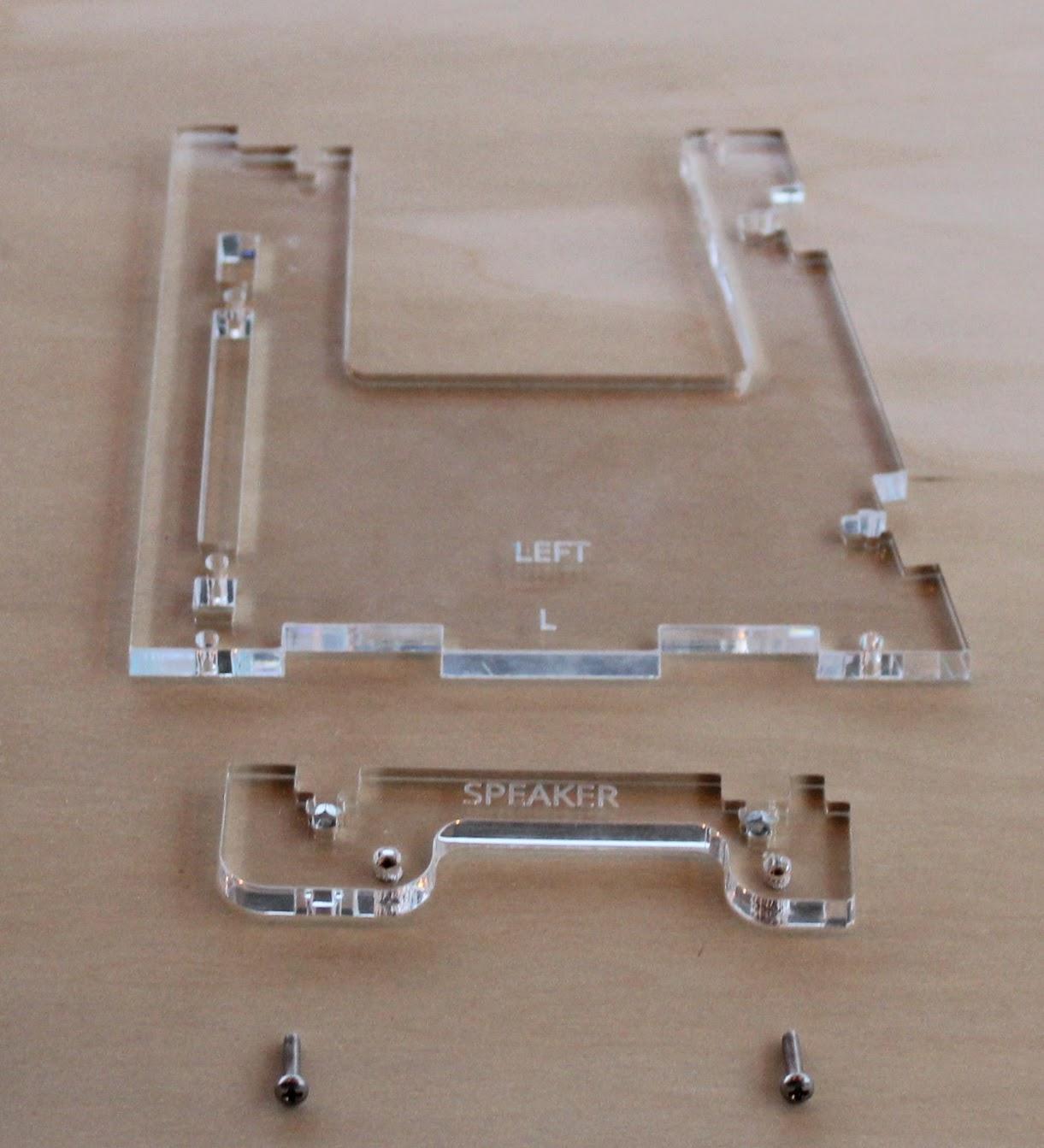
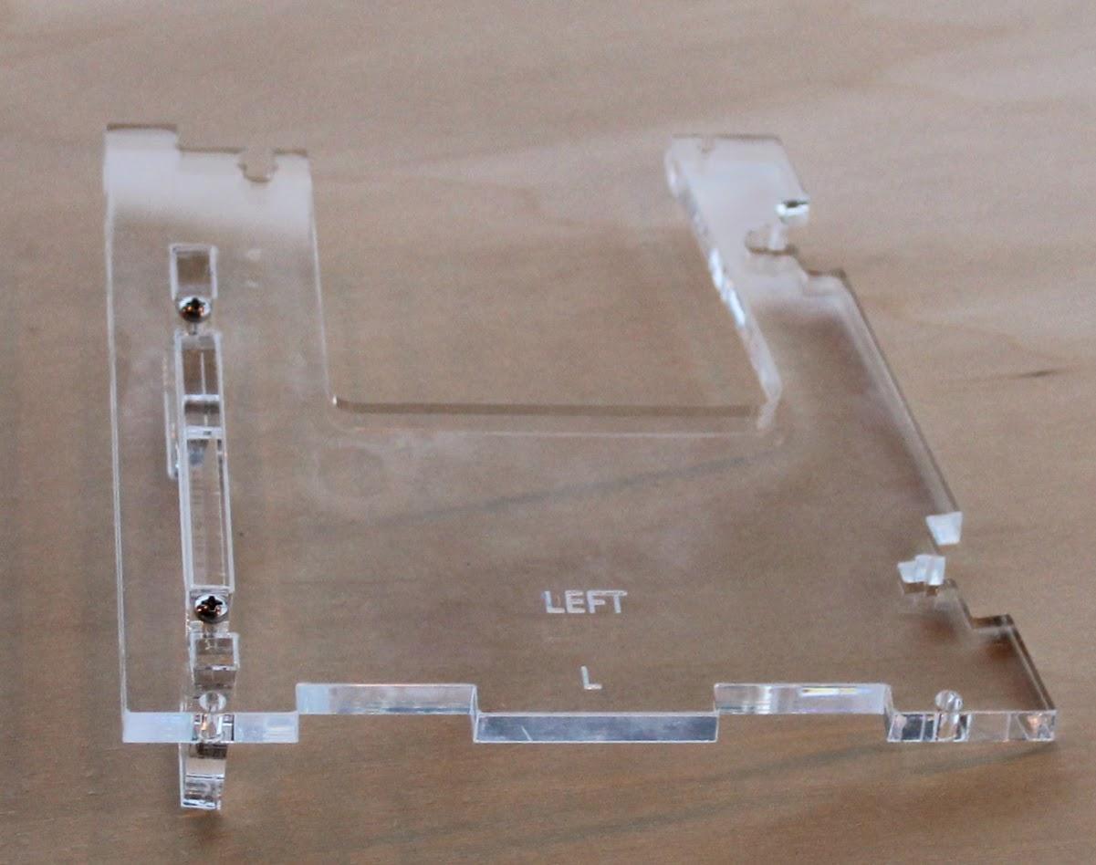
Place the 2.5mm x 16mm flat head stainless steel screws in the fan as shown making sure to put the fan on the inside of the right hand acrylic piece.
Thread the 2.5mm stainless steel nuts onto the screws as shown. This can be a bit tricky. If the screw doesn't protrude from the acrylic you might want to check to be sure you have the correct ones. The flat head screws are the LONGEST screws in the kit.
Once the fan is secured, connect the speaker tabs to the left and right hand sides as shown.
Assemble Camera and Screen
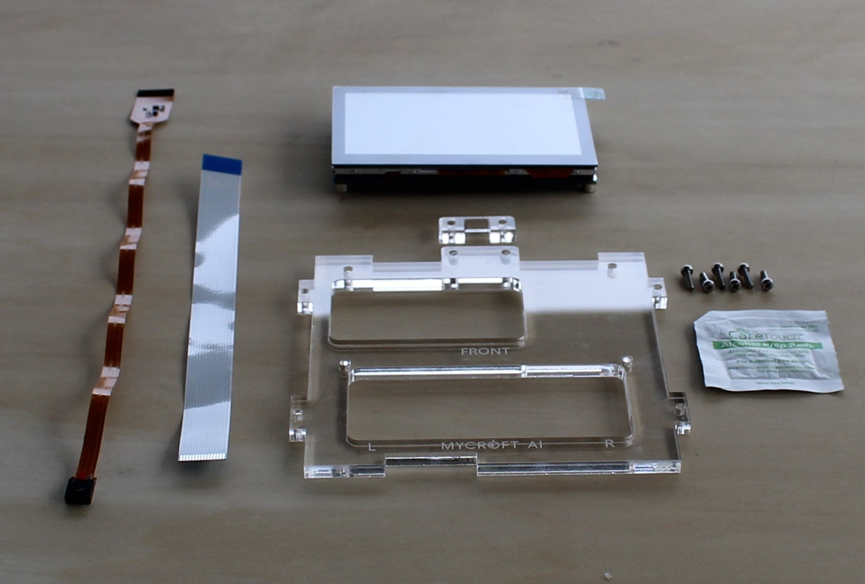
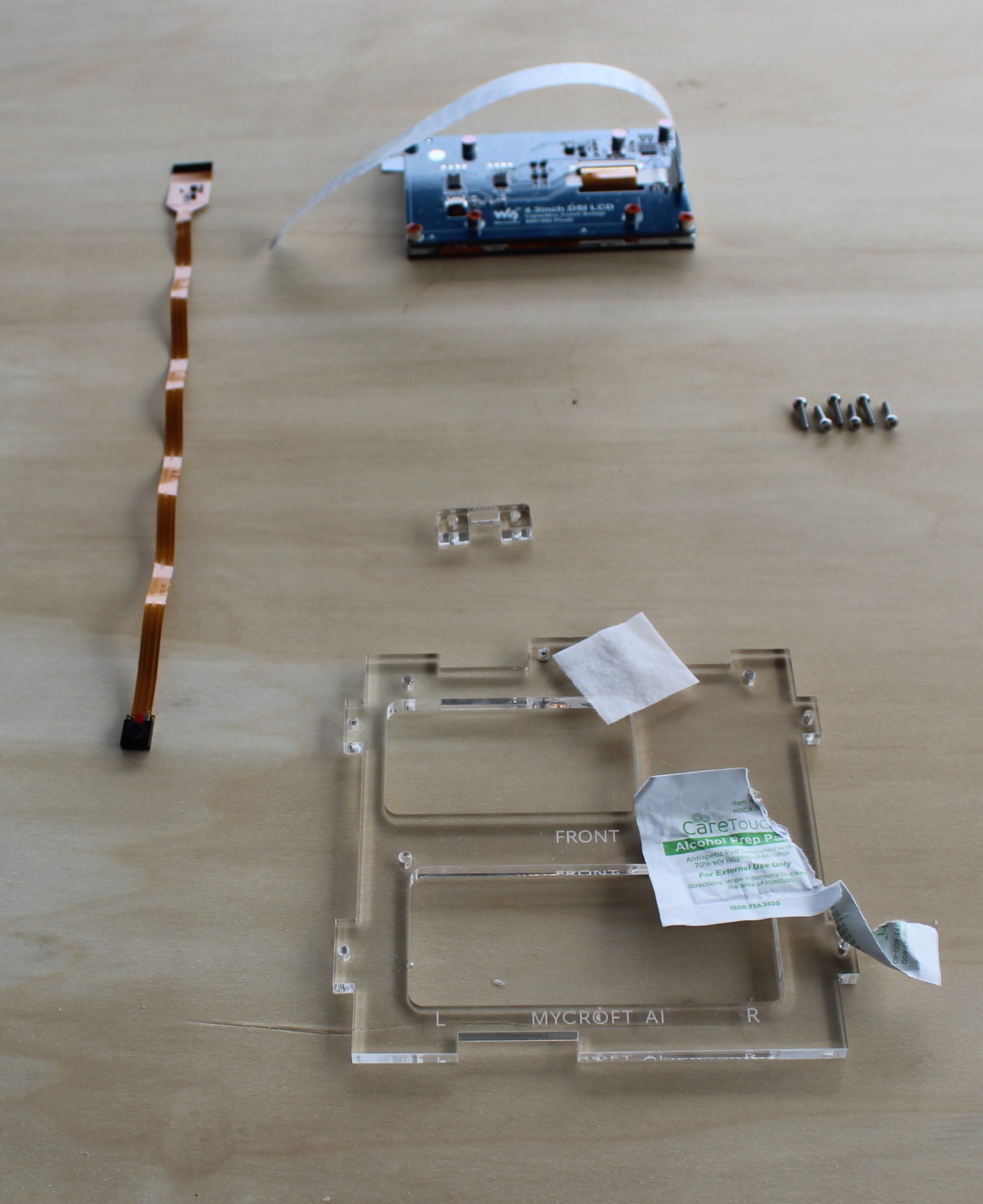
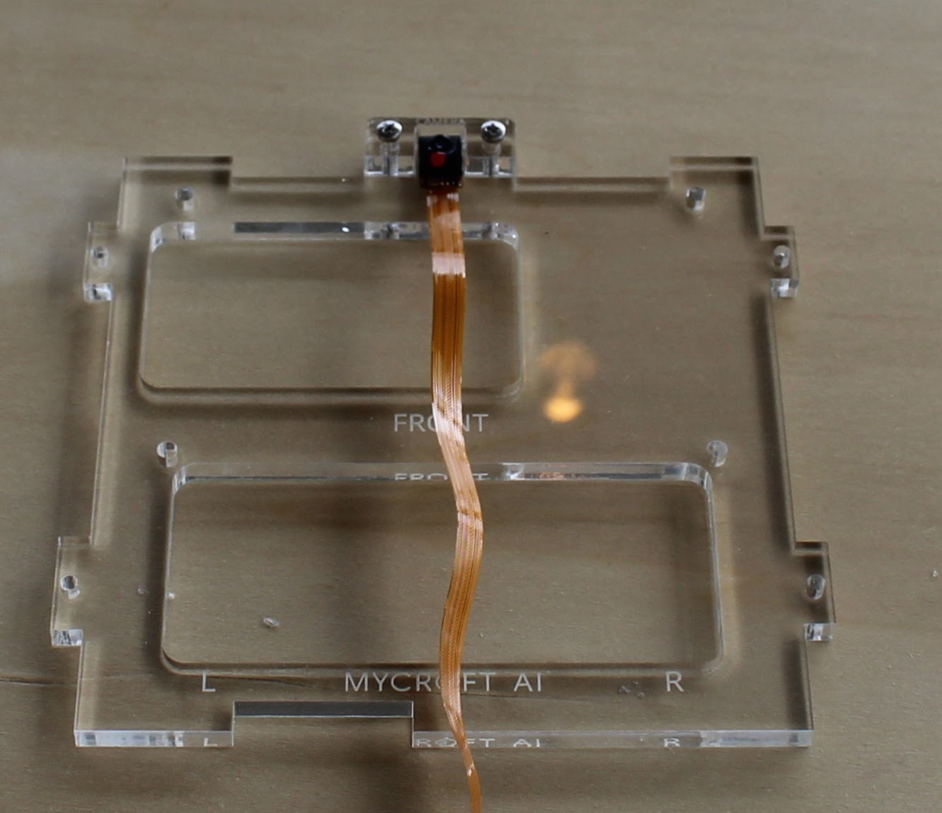
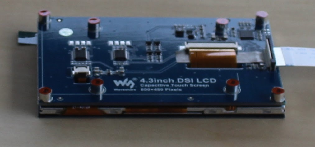
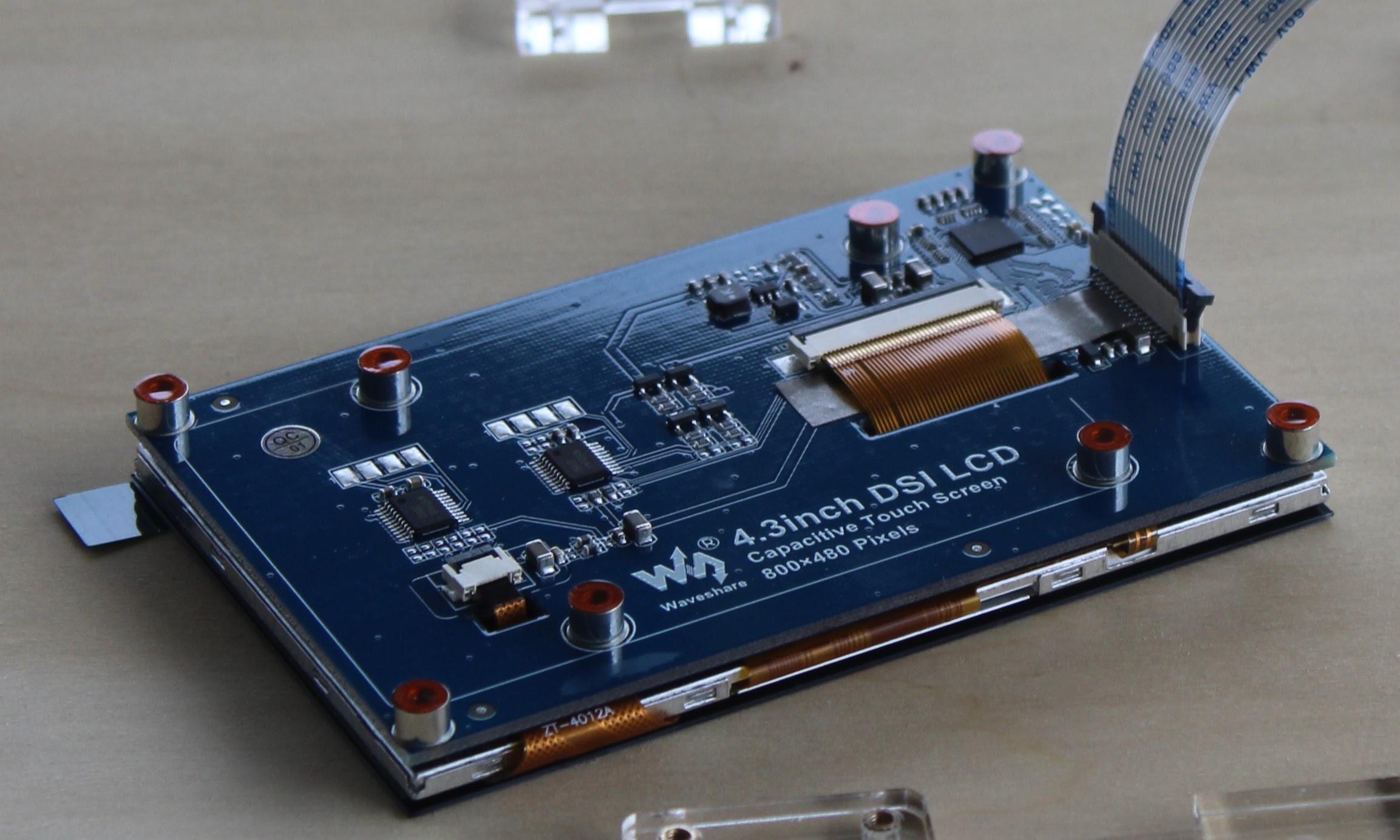
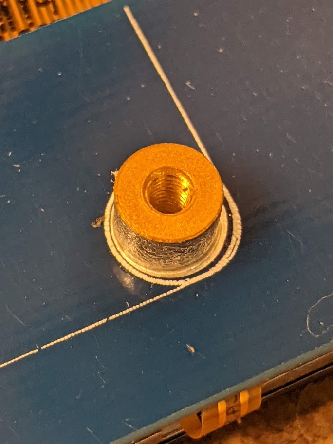
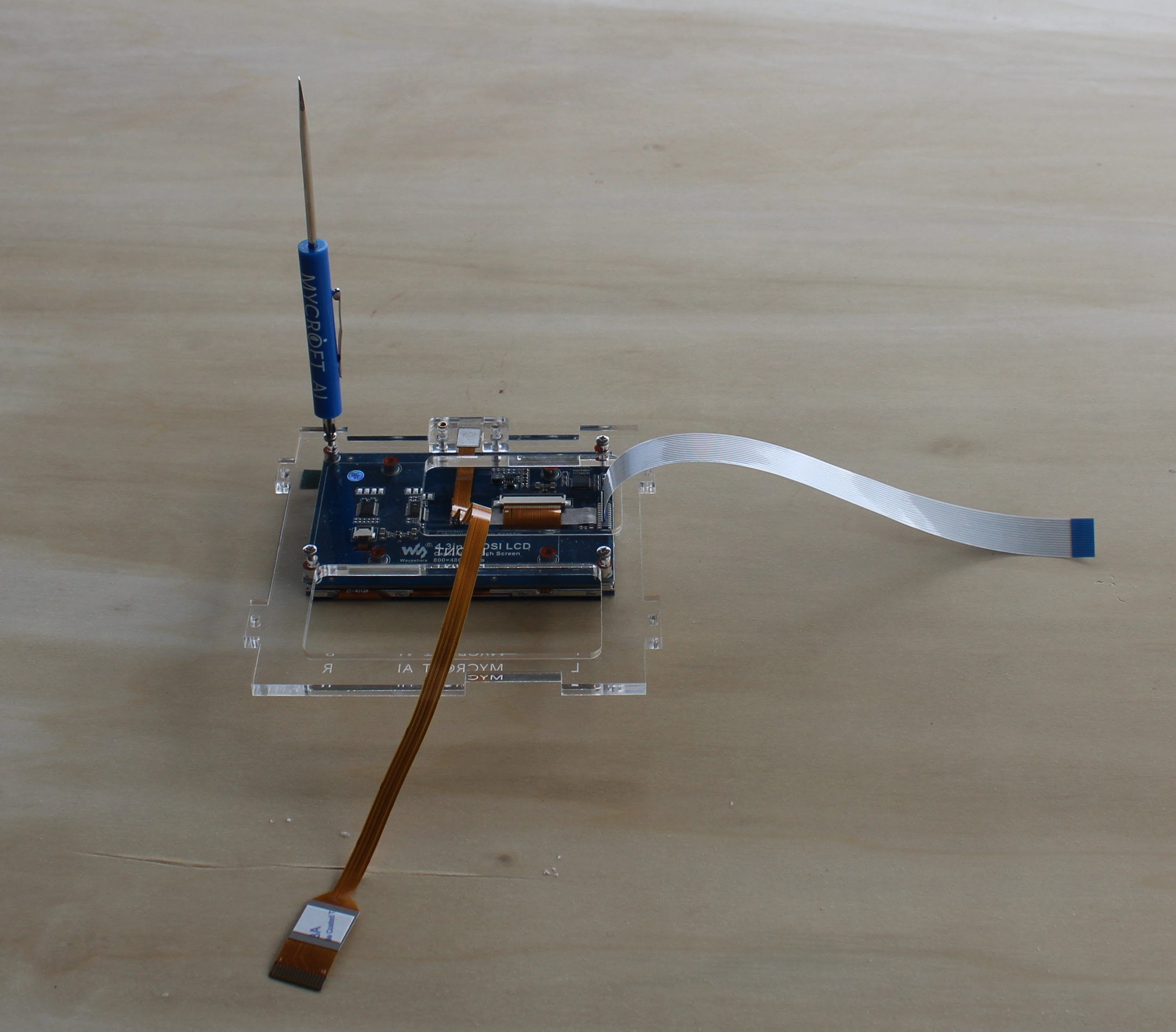
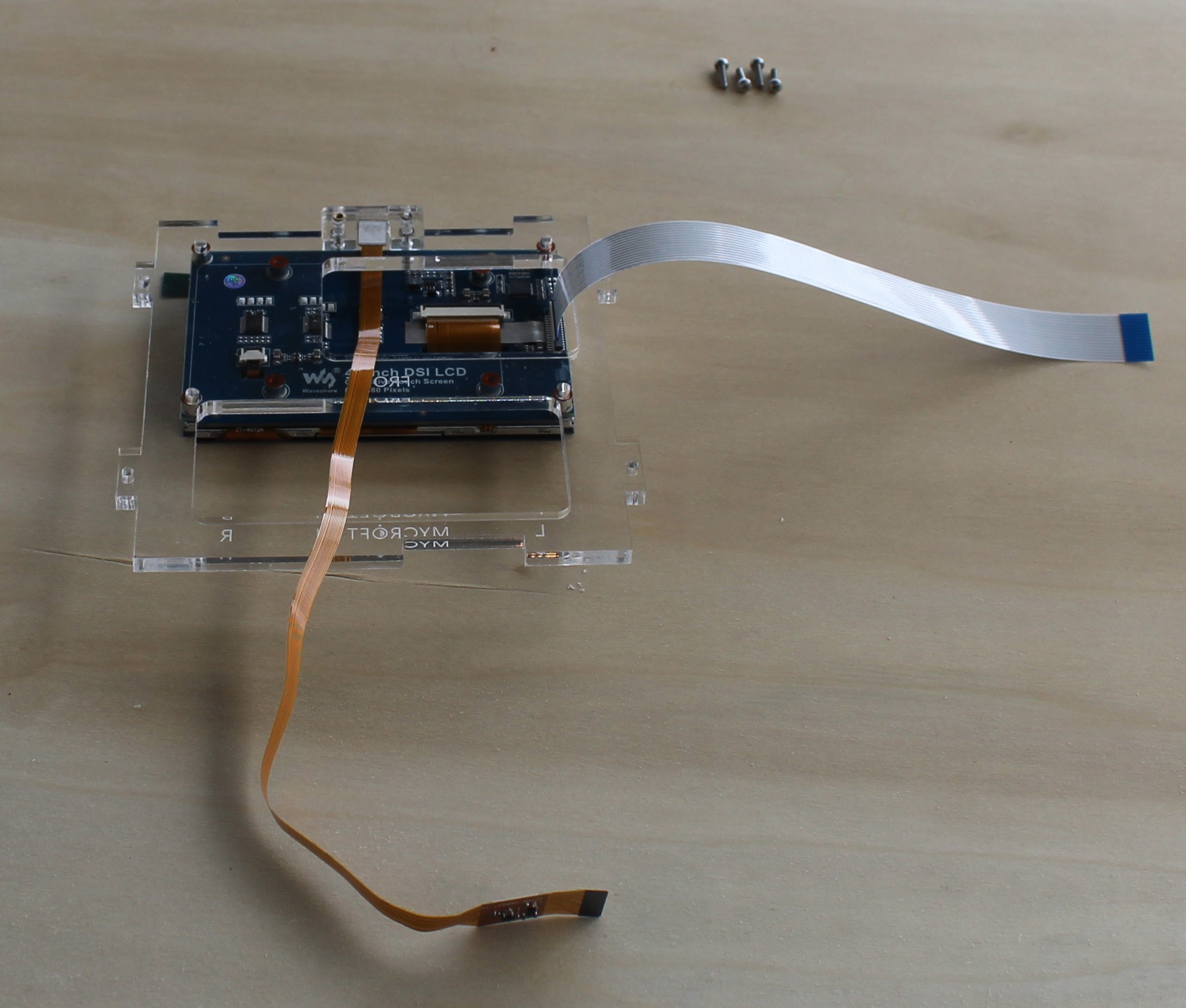
Clean off the top tab of the front panel with the provided alcohol wipe.
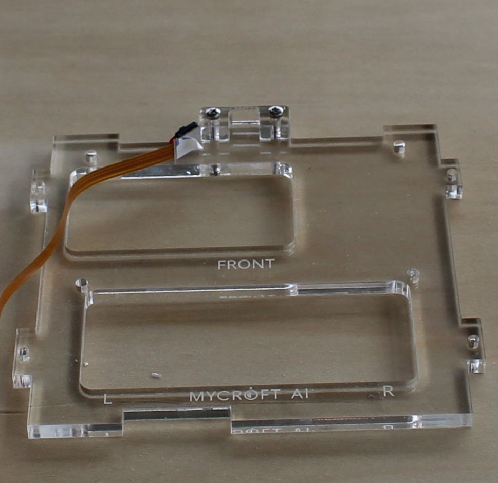
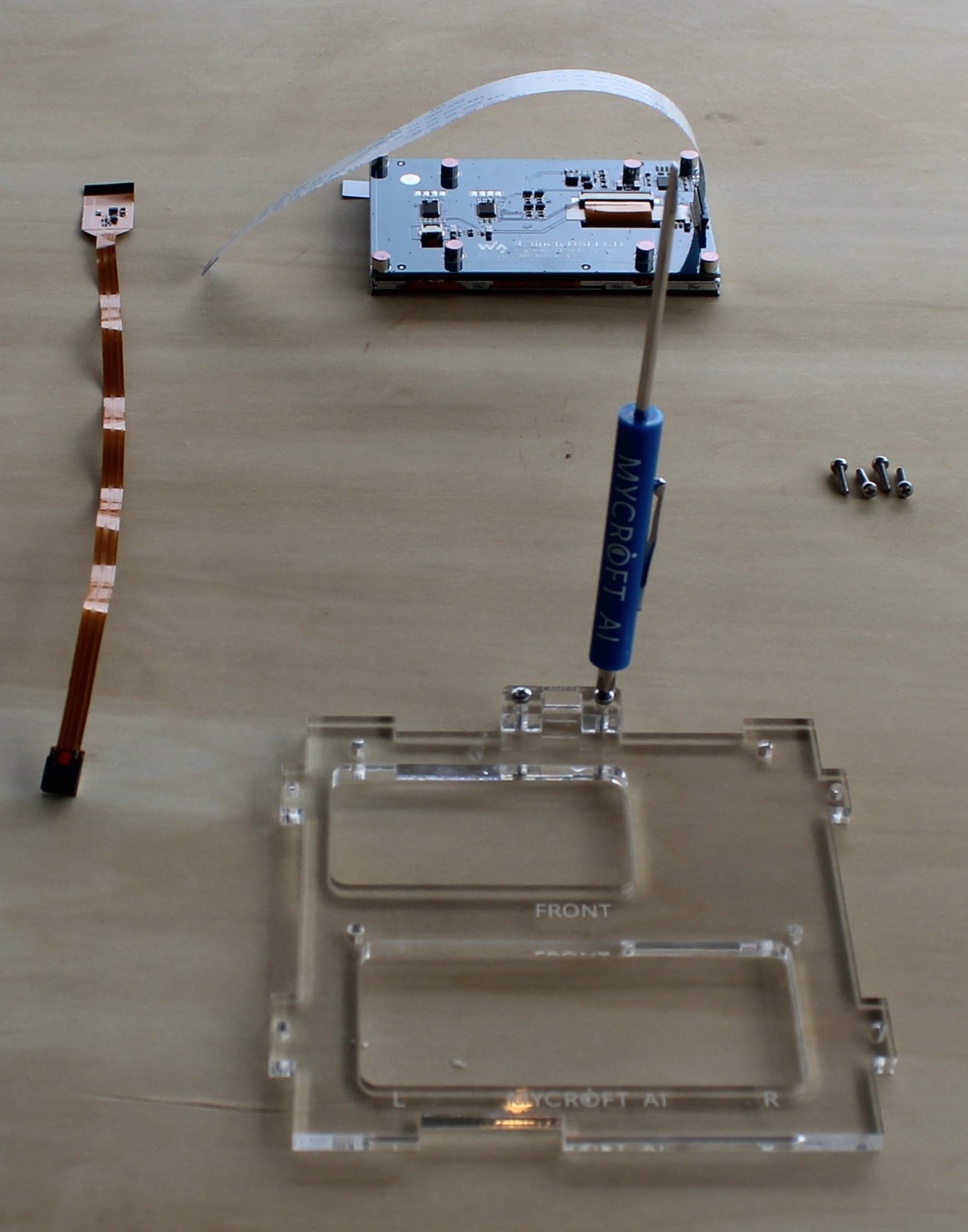
Install the alignment bracket to the front side of the panel with two 2.5mm x 10mm stainless steel pan head screws.
Remove the adhesive backing from the camera and firmly press into the alignment slot.
The DSI cable is a ribbon cable with conducting pins on one side. We use them to connect video devices ( cameras and screens ) to the Pi. The cable sends both the video signal and the power to the screen.
Connect the DSI cable with the conductors ( shiny part ) oriented as shown. GENTLY! pull out the arms of the DSI connector, slide the DSI cable into it and GENTLY push the arms back down
Remove the orange adhesive cover from the threaded posts on the back of the touch screen.
Orient the screen face down and align the acrylic front as shown. Route the cables as shown and secure the screen to the front using four 2.5mm x 10mm stainless steel pan head screws.
Prepare the Raspberry Pi
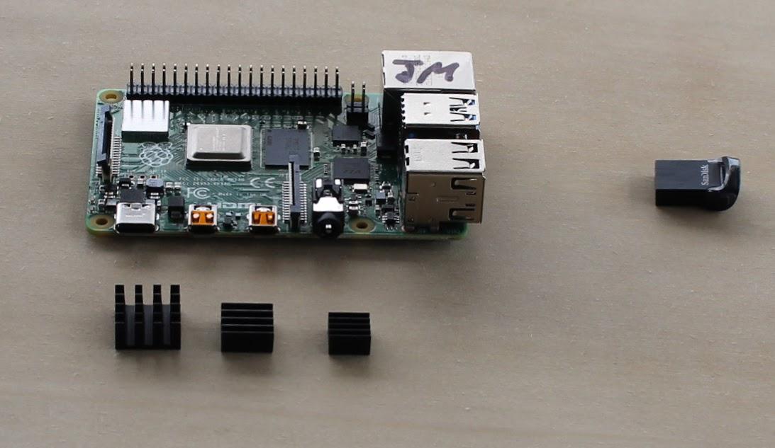
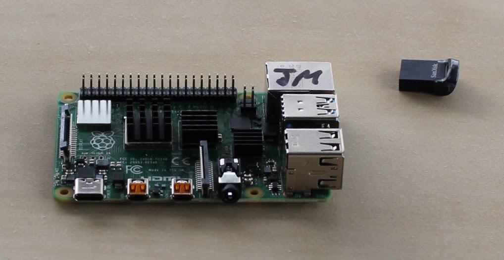
One at a time, remove the adhesive backing from the three heat sinks and install them on the processor, ram and USB chips on the Raspberry Pi.
Flash Image Onto USB Drive
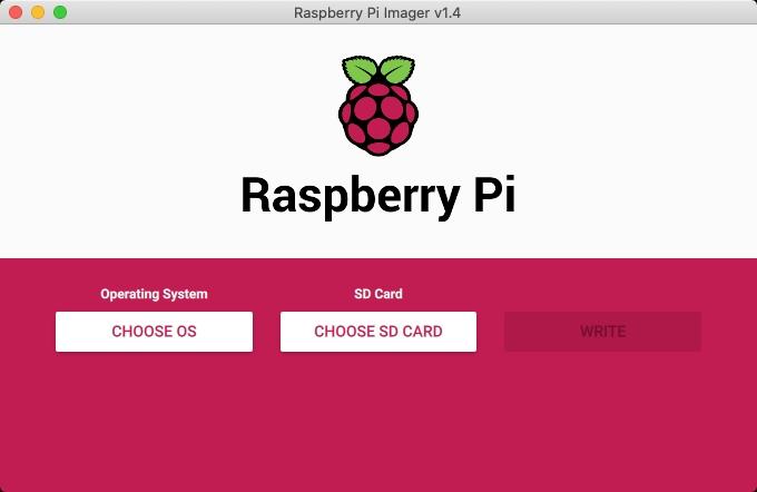
Hopefully you started downloading the Mark II software image at the beginning of these instructions.
If not, please take a moment to download the image now.
Windows/MacOS/Ubuntu
If you are using Windows, MacOS or Ubuntu use the Raspberry Pi Imager to flash the custom image you downloaded onto the provided USB drive.
NOTE: You must choose the "Use Custom" option and select the image you downloaded.
Linux
If you are using Linux go ahead and use the dd utility to flash the image onto the supplied USB drive.
NOTE: If you use the wrong usb device in these commands you can unintentionally nuke your hard disk. You've been warned!
Plug the USB drive into your Linux device.
Find the USB name
Simply run the dmesg command after inserting the USB drive:
> dmesg
Filter out info using the grep command:
> dmesg | grep -i usb
> dmesg | grep -i 'attached'
Sample output:
[ 5.793647] sd 0:0:0:0: Attached scsi generic sg0 type 0
[ 5.795335] sd 0:0:0:0: [sda] Attached SCSI disk
[ 7.421446] sd 6:0:0:0: Attached scsi generic sg1 type 0
[ 7.438791] sd 6:0:0:0: [sdb] Attached SCSI removable disk
[ 334.349540] sd 6:0:0:0: Attached scsi generic sg1 type 0
[ 334.365272] sd 6:0:0:0: [sdb] Attached SCSI removable disk
/dev/sdb is my usb stick.
Additionally, you can run the following lsblk command. It lists information about all available or the specified block devices:
> lsblk
Once you know where the USB drive is, you simply dd the image file directly onto the device. In this example we are using "sdX" as the USB drive's location, but yours will likely be "sdb", "sdc" or similar.
> gunzip -c /path/to/image.tar.gz | dd of=/dev/sdX status=progress.
Insert USB Drive
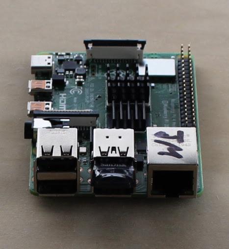
Now that you've flashed the image onto the USB drive, insert it as shown.
Final Assembly - Sides
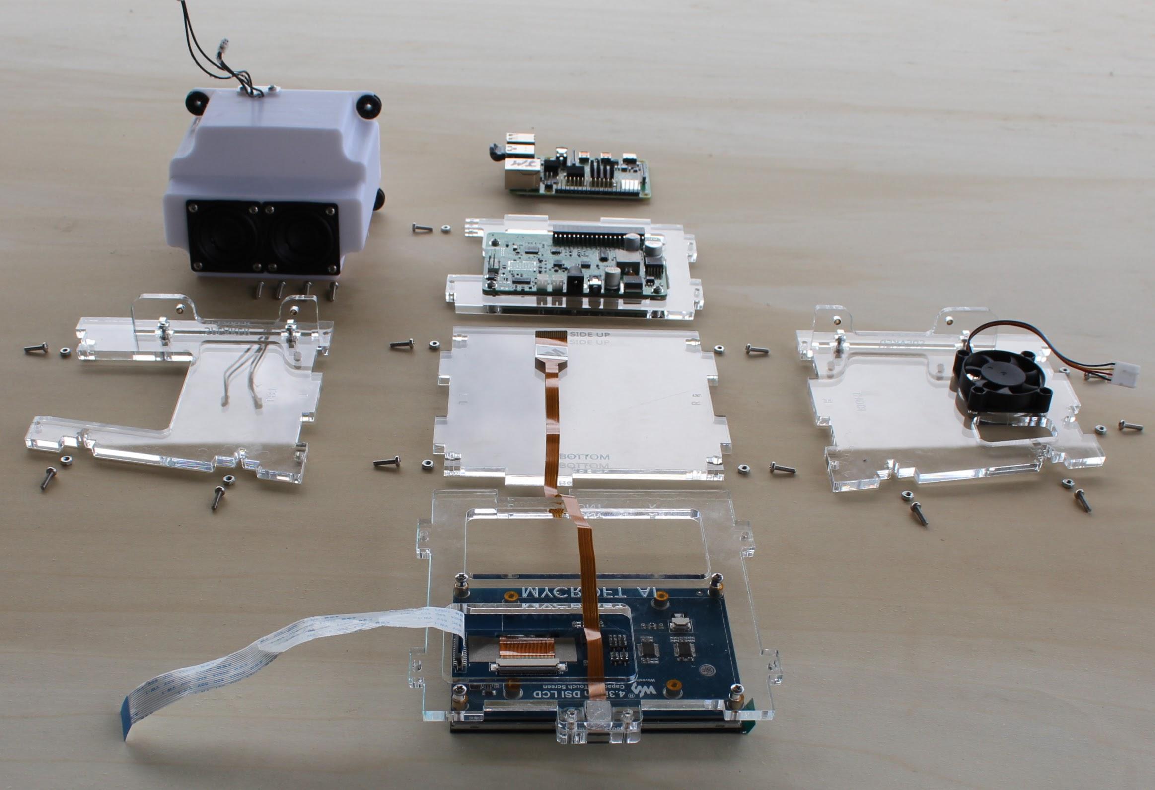
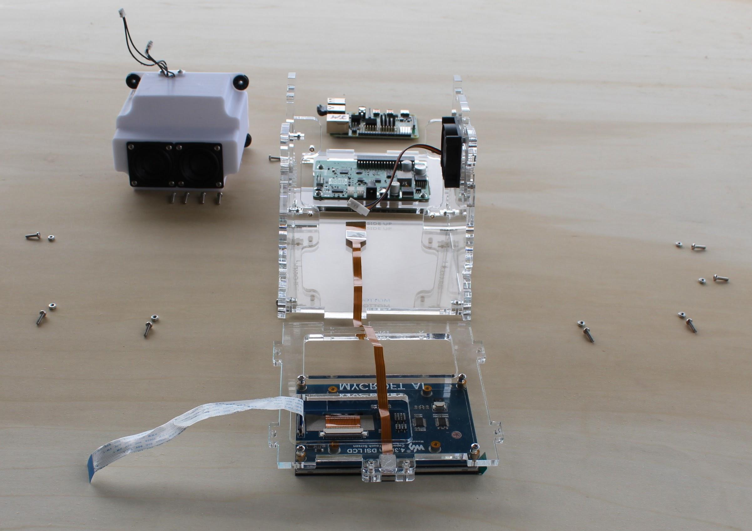
Lay all of the parts out as shown.
Secure the sides to the bottom by inserting the 2.5mm nuts into the provided slots with tweezers, standing up the sides and securing them with 2.5mm x 10mm stainless steel pan head screws.
Final Assembly - Pi
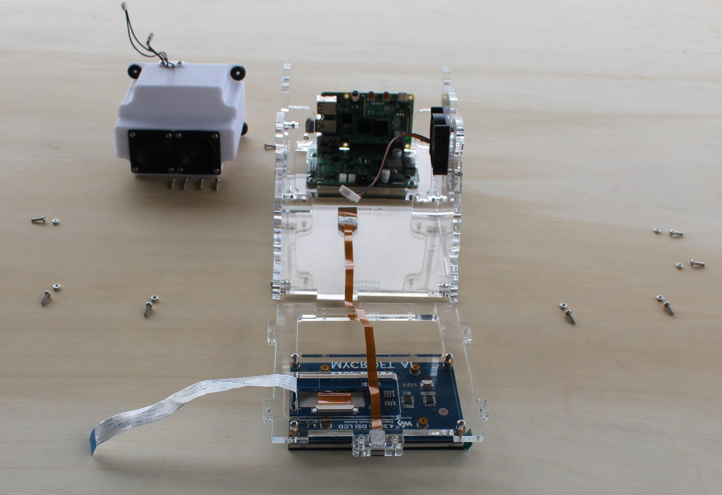
Attach the Raspberry Pi to the SJ201 daughter board using the 40 pin connector.
Final Assembly - Front
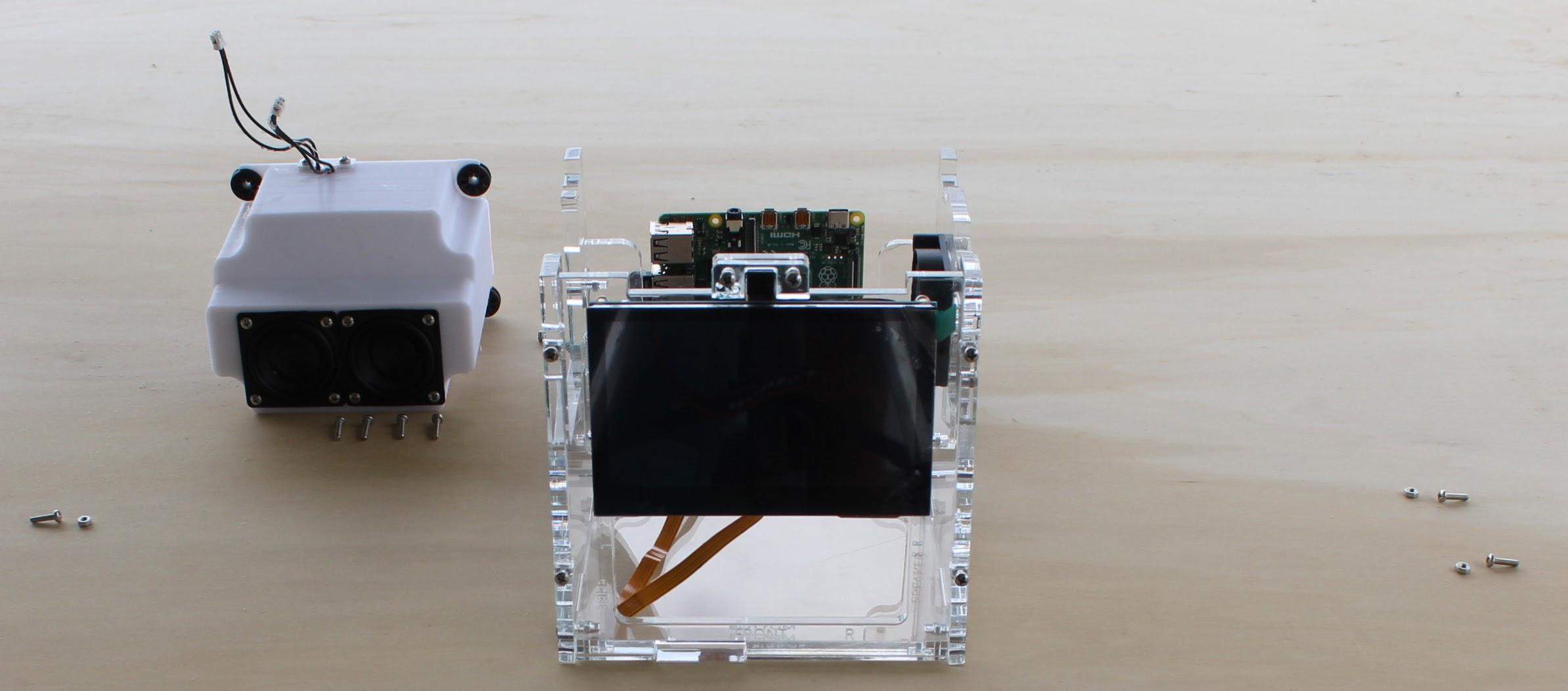
Attach the front to the bottom and sides by inserting the 2.5mm nuts into the provided slots and securing them with the 2.5mm x 10mm stainless steel pan head screws.
Final Assembly - Cables
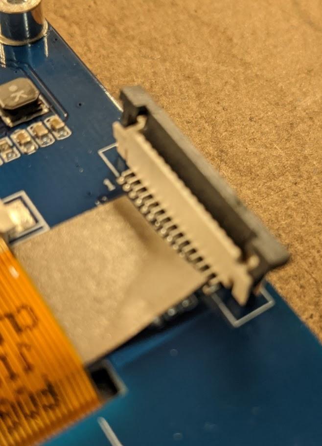
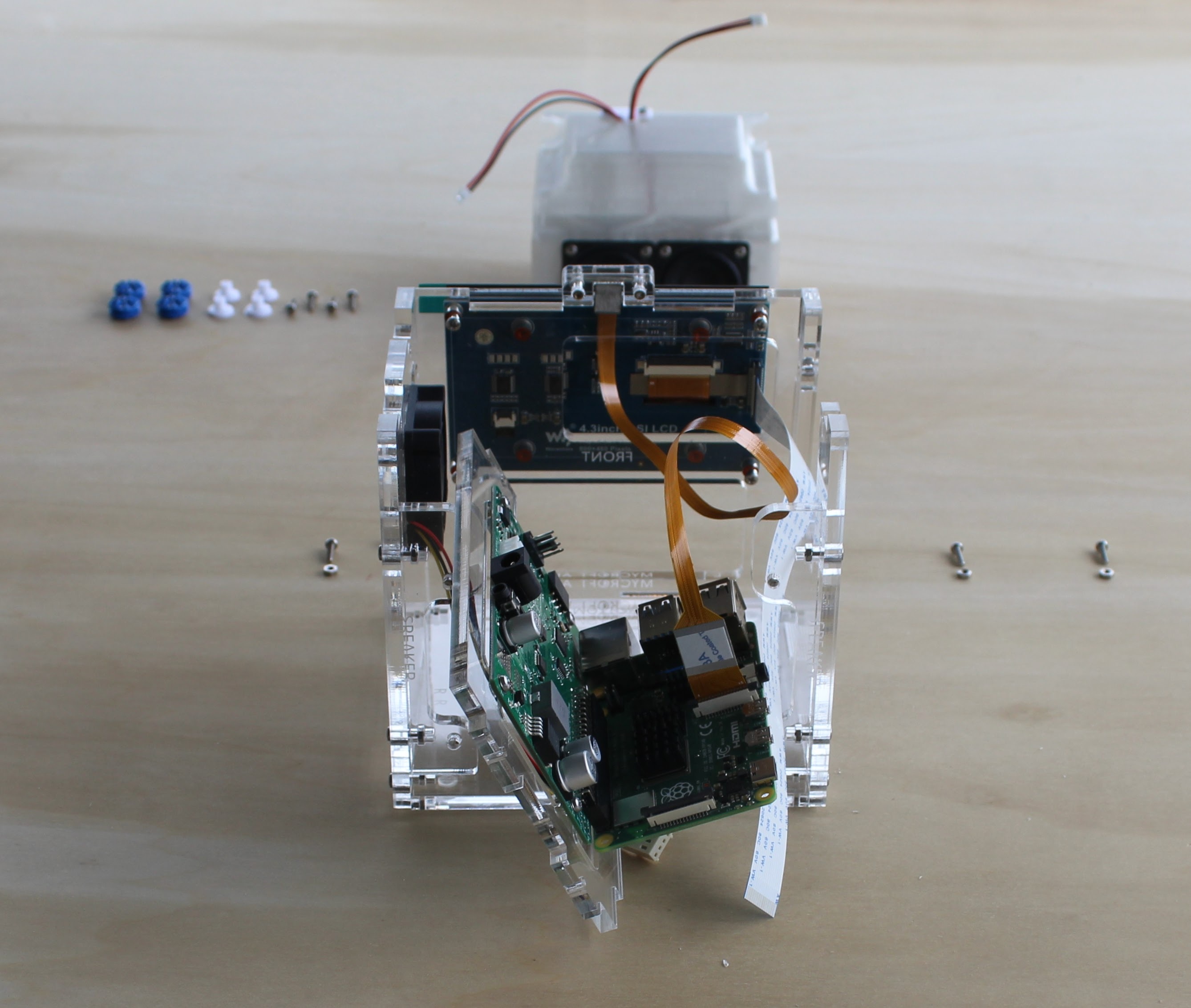
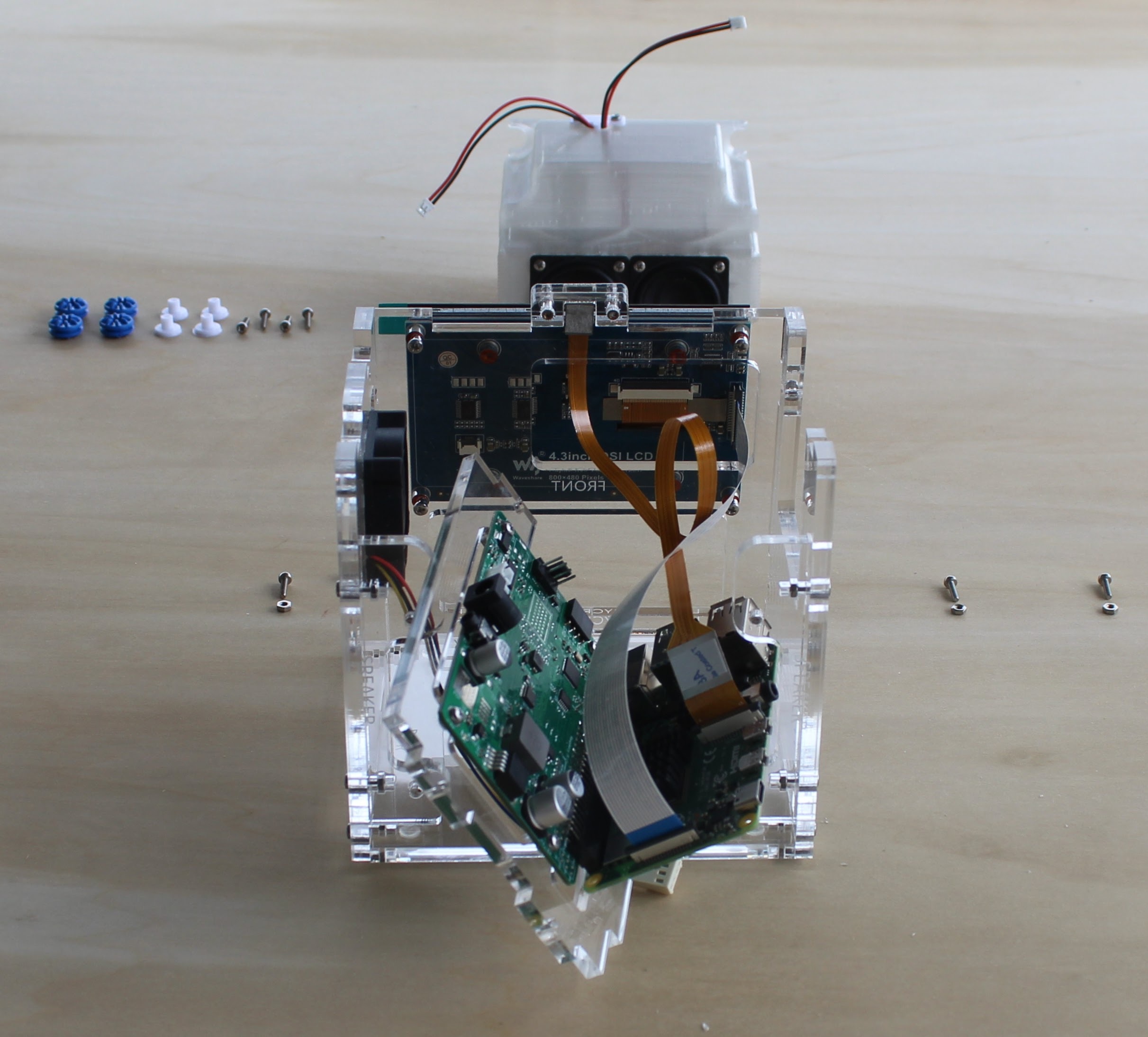
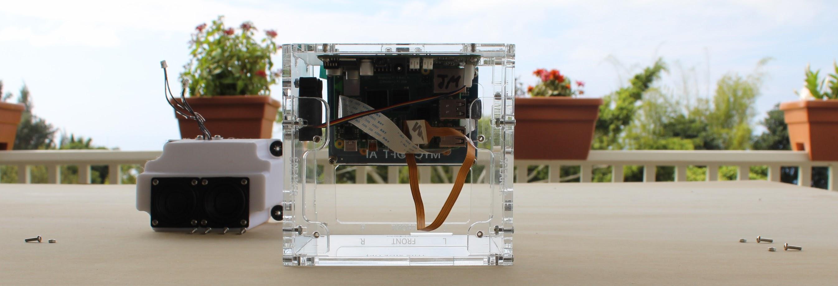
This step takes some dexterity, so please be careful and patient. If you have to force anything you are doing it wrong. Step back, breath, and carefully try again.
Attach the screen and camera cables to the Raspberry Pi by carefully pulling the grey tab straight out, inserting the cable with the metal pins facing the white side of the connector and carefully pushing the grey tab in.
Final Assembly - Secure Top
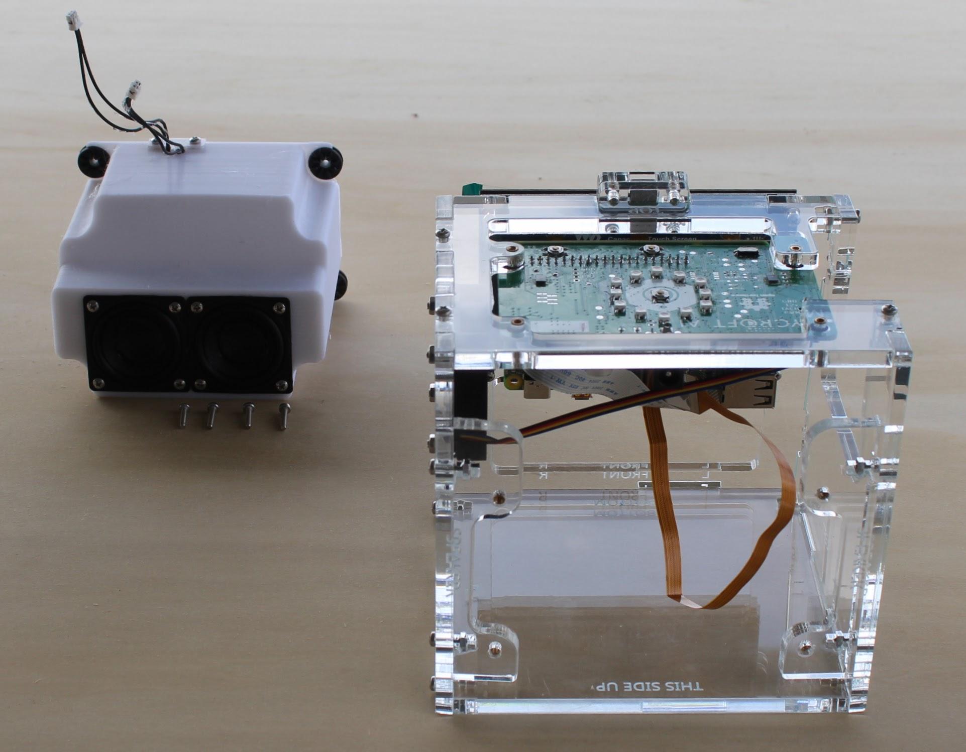
Secure the top to the sides by inserting 2.5mm nuts into the provided slots and then securing them with 2.5mm x 10mm stainless steel pan head screws.
Final Assembly - Install Speaker Enclosure
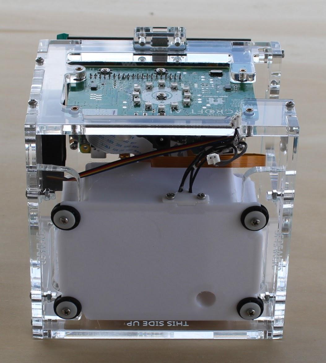
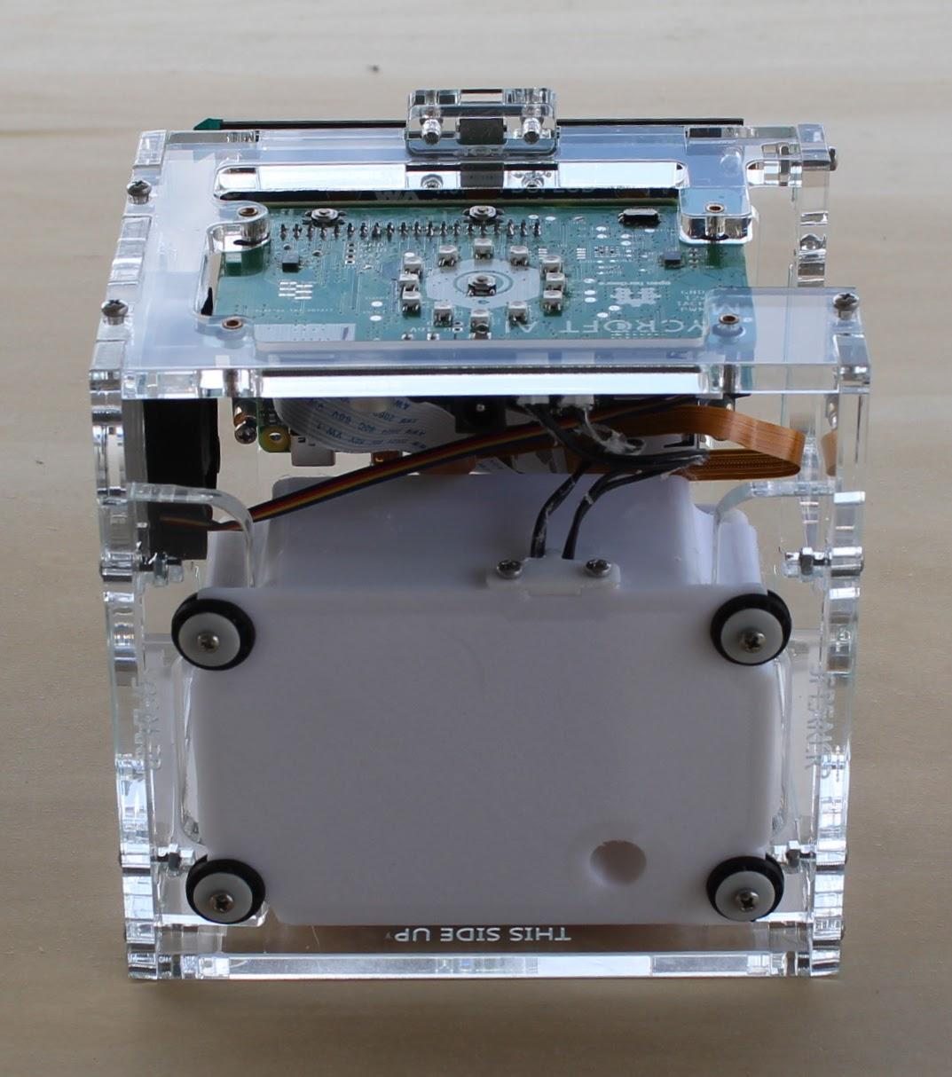
Note: These screws are slightly longer than the 10mm screws.
Slide the speaker enclosure into the back of the device and secure it with four 2.5mm x 12mm stainless steel pan head screws.
The screws go through the center of the white spacers which, in turn, go through the center of the sound isolating grommets.
Assembly Complete
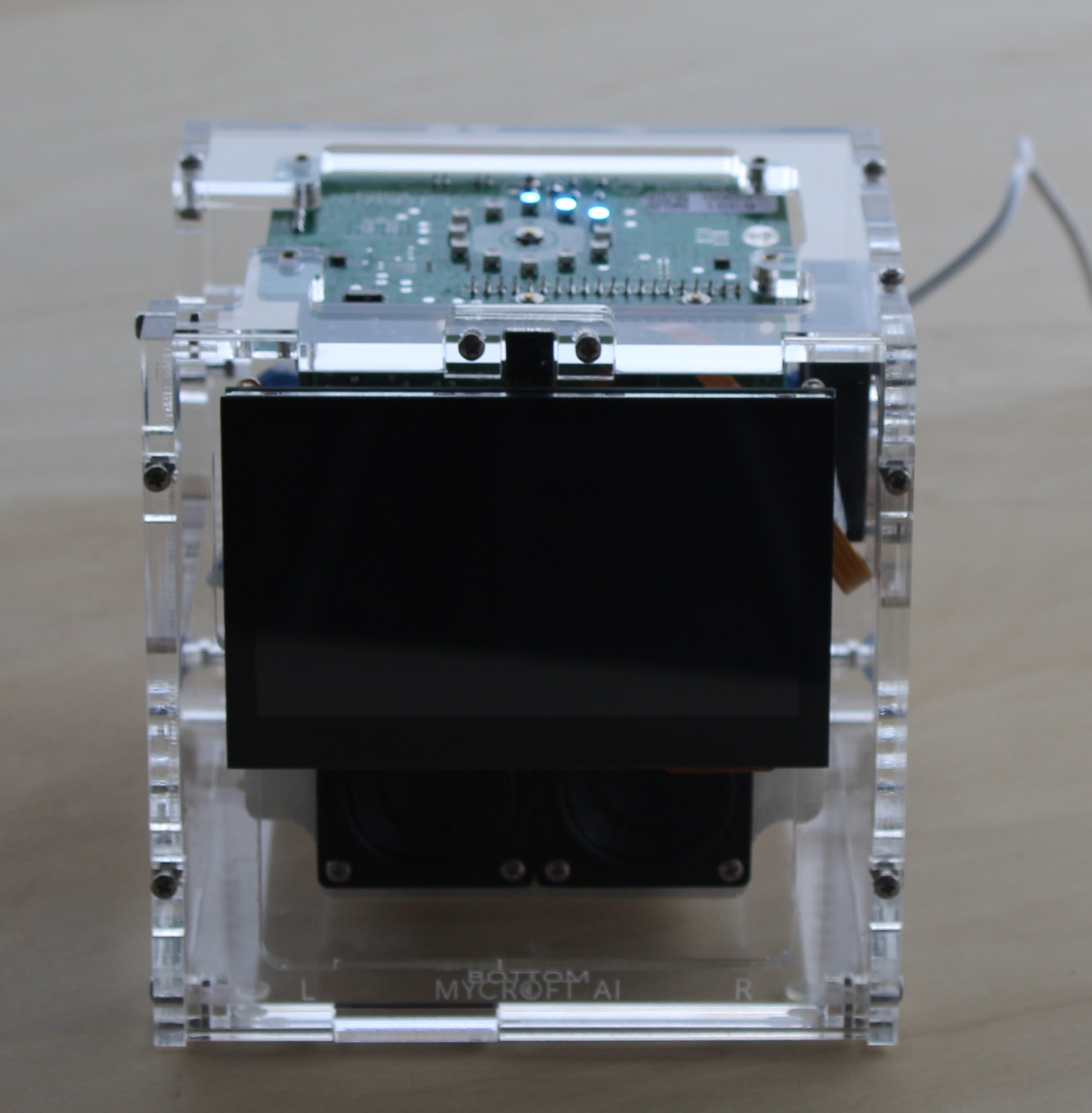
Before turning the device on be sure to create an account at https://home.mycroft.ai
Clean any fingerprints off of the device and plug it in with the provided 12V power supply.
Follow the instructions to pair the device with your Mycroft account.