Music Visualiser Table
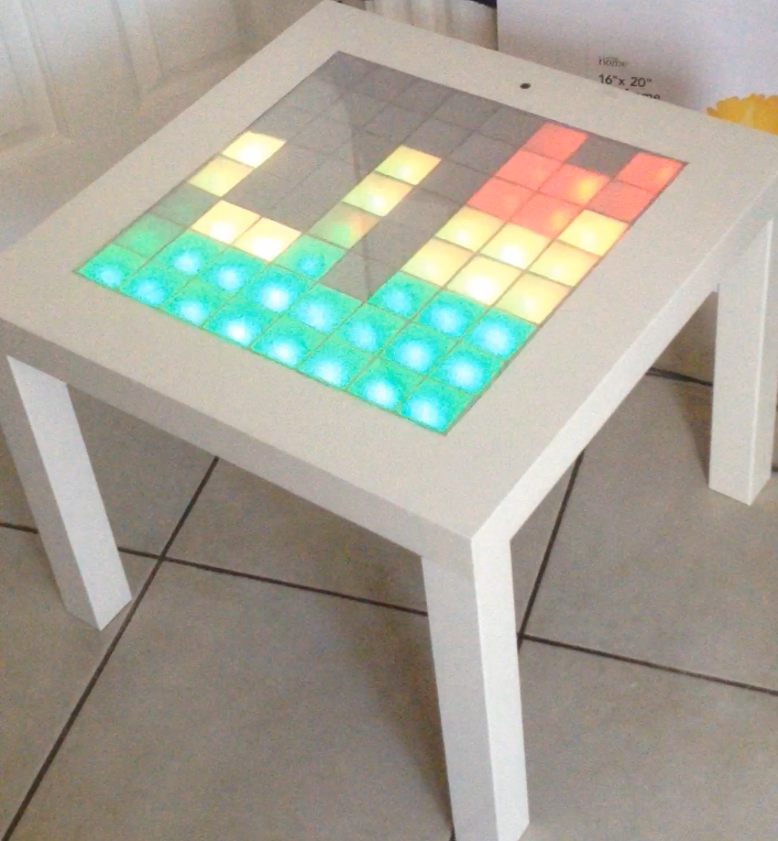
This Instructable will hopefully give you all you need to put together a reactive music led table.
*** Following questions/suggestions/queries, I've added a full breakdown for making the LED array. I hope it helps those with questions. I've also added some pictures of the circuit boards - These are directly from Adafruit, and I give them full credit - what they do is awesome!***
I based it on the Music Visualiser at Music Visualiser - Adafruit. The code is from there, the circuit is from there - all I really created was a big led matrix, and put it into an Ikea table!
Really, I wanted to make a full arduino tetris table, but I had most of the spare parts and wood available to make this, so that's what I did.
As a picture is worth a thousand words, there are lots of pictures as I hate writing!
Modify the Table
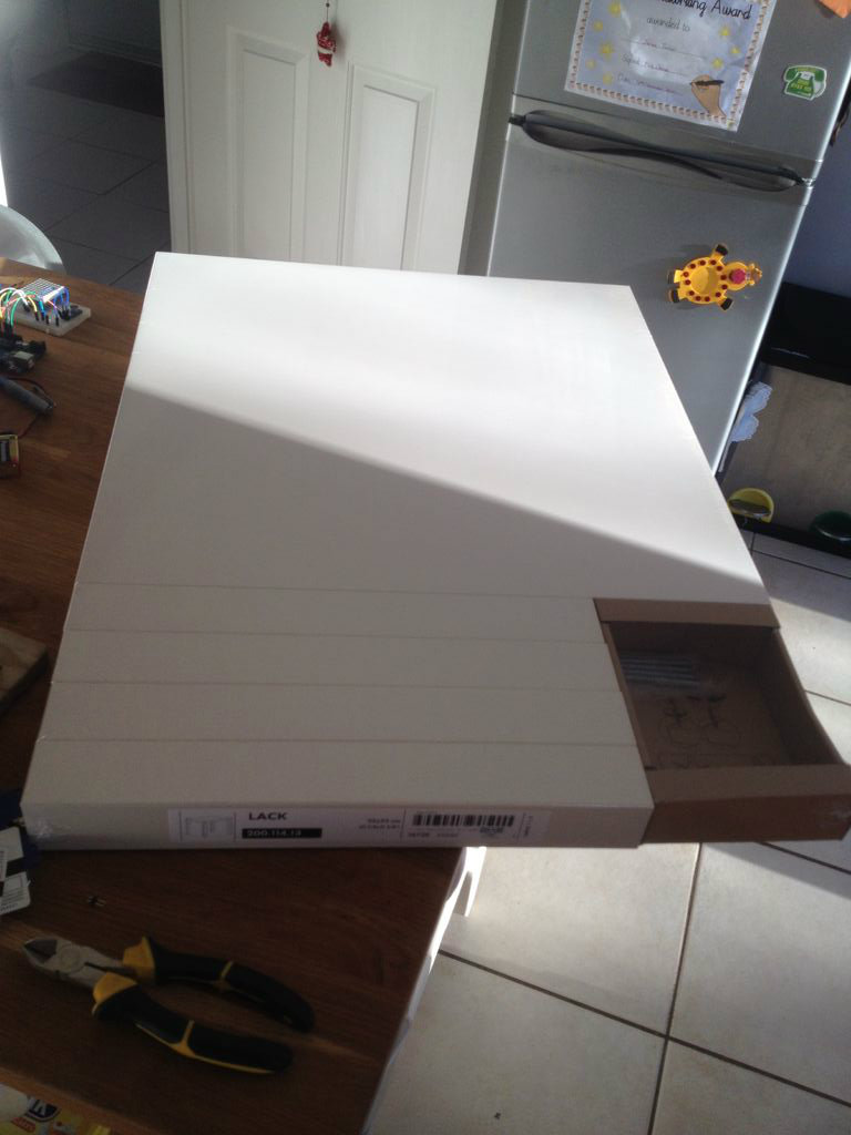
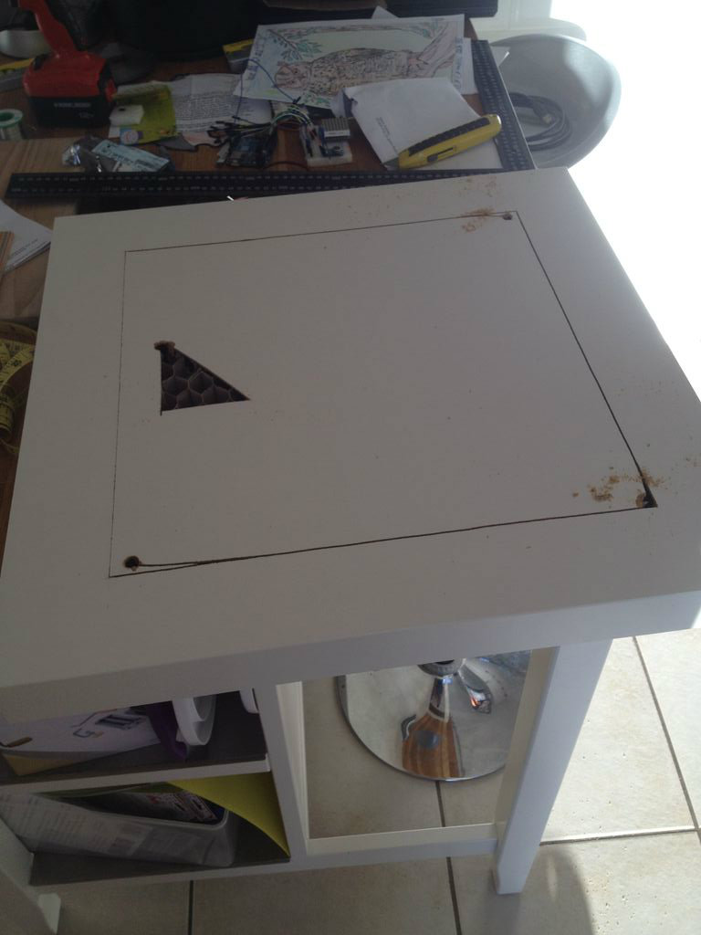
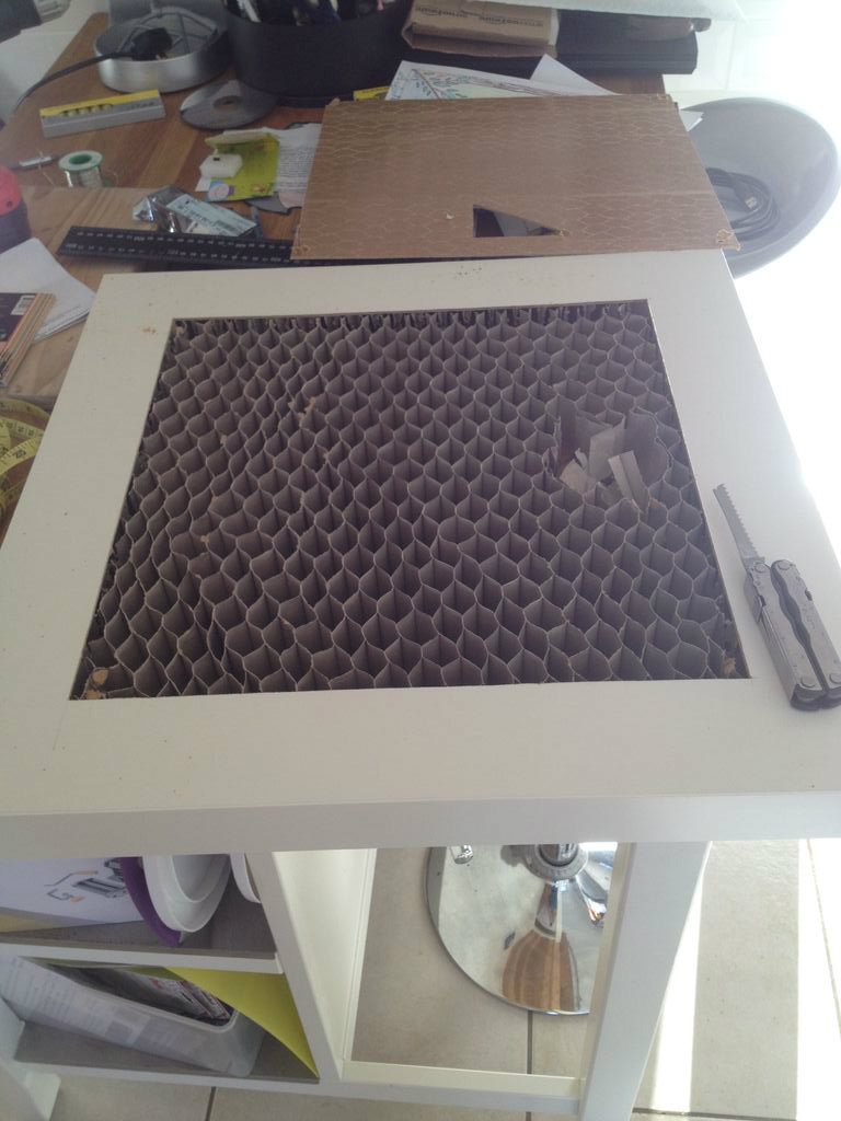
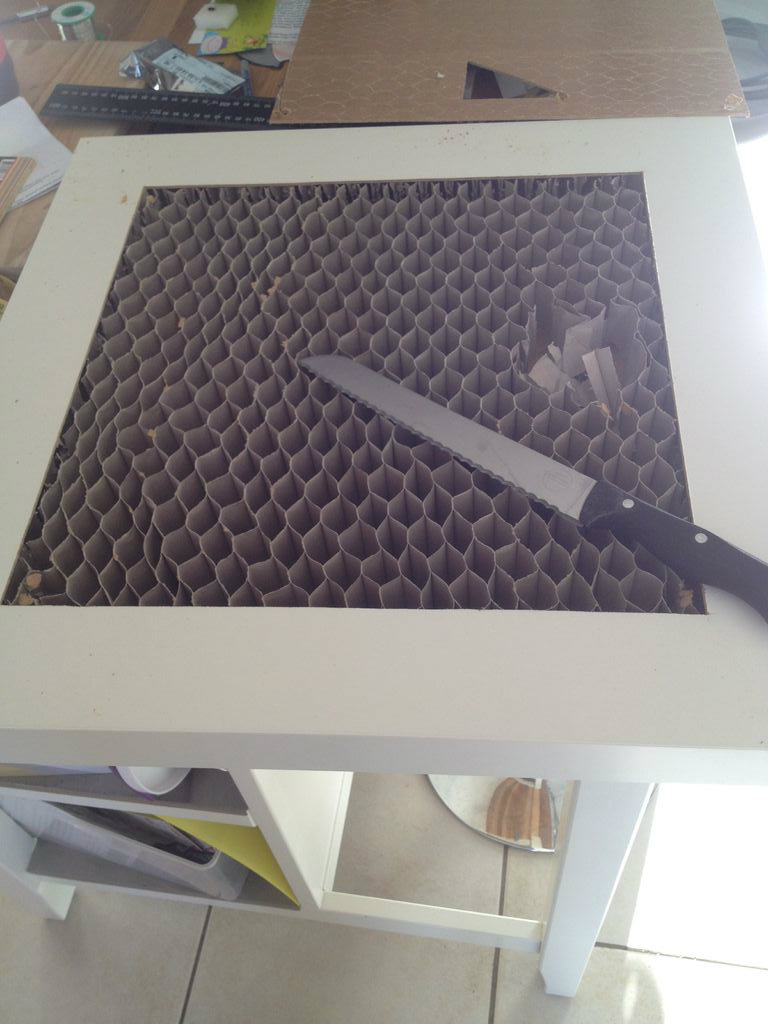
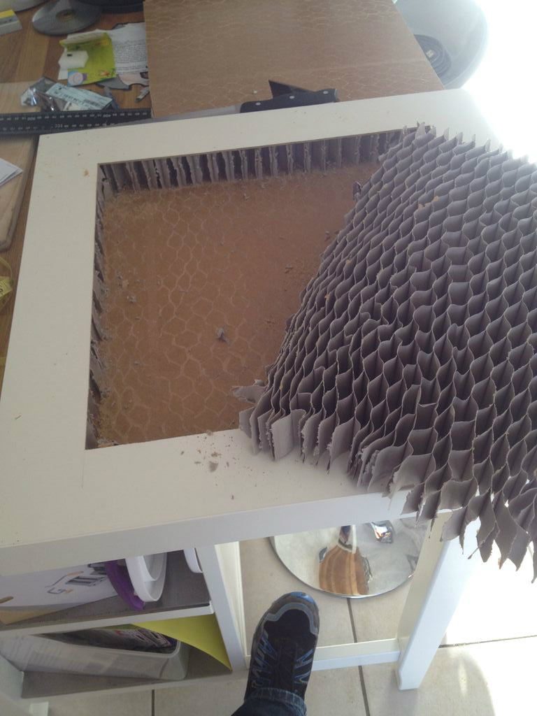
Start with an Ikea Lack table - the matt white was on special at £5, so that's what I used.
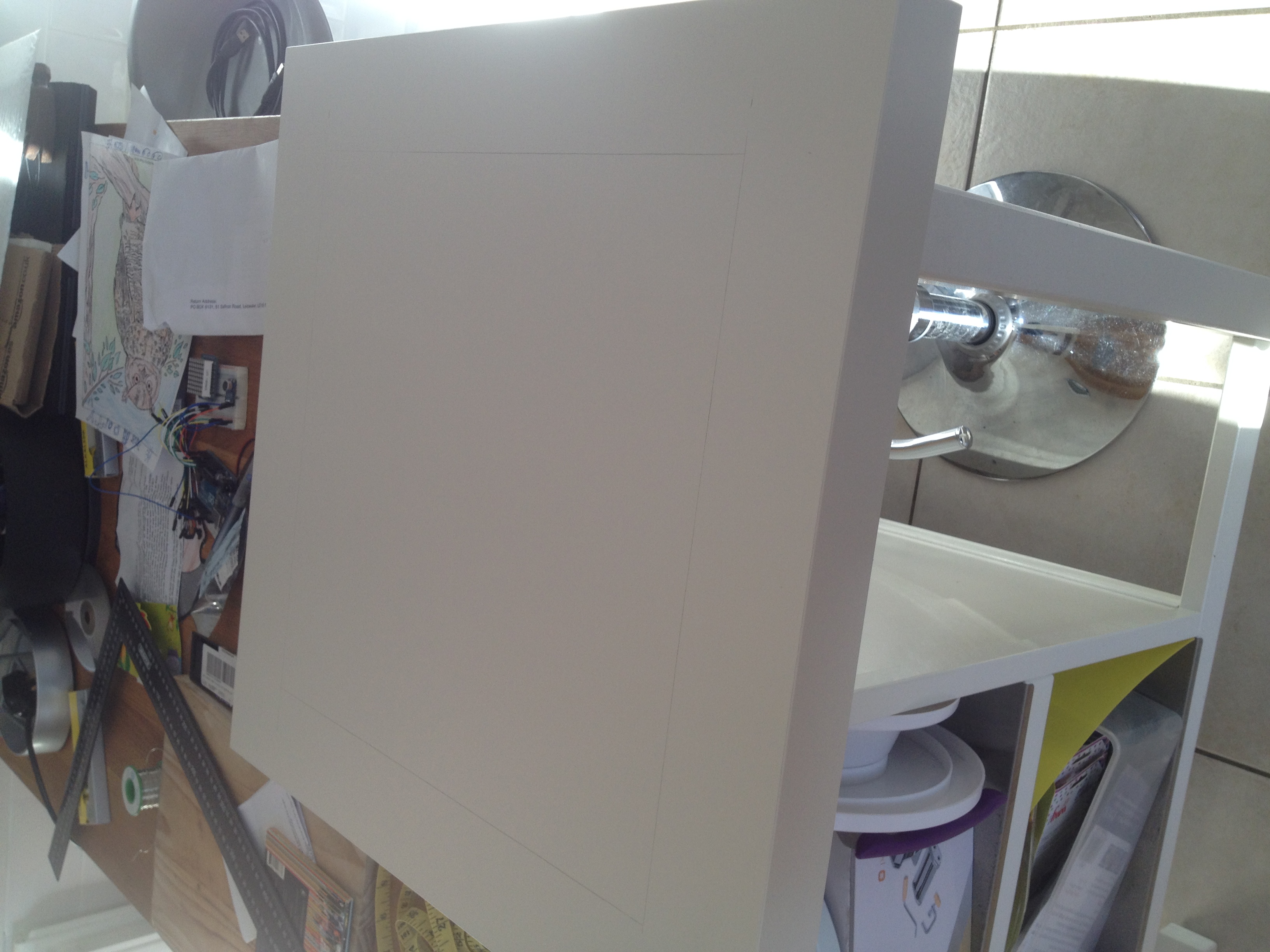
Draw a square on the table - mine was 40cm * 40cm - giving me 5cm2 sections.
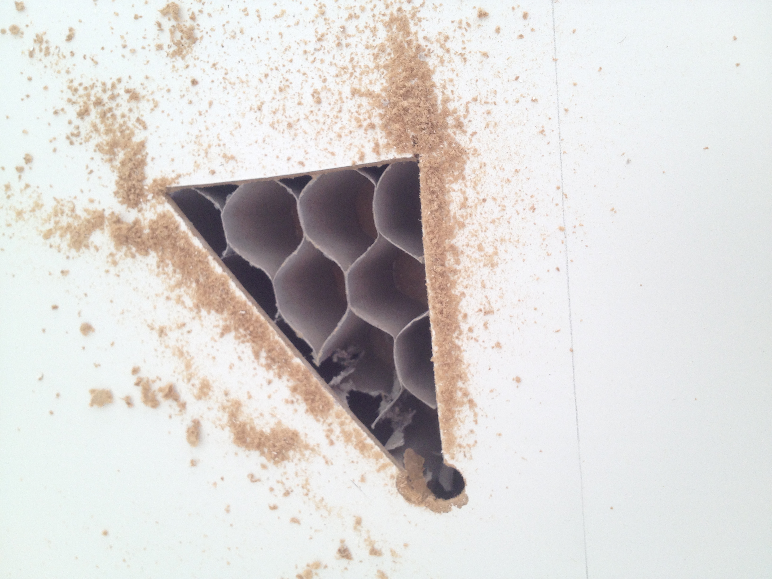
Not knowing what the table was made of, I cut a small hole to look inside.
Happy with what I found, I cut the square, and removed the honeycomb cardboard inside.
Realise Your Mistakes
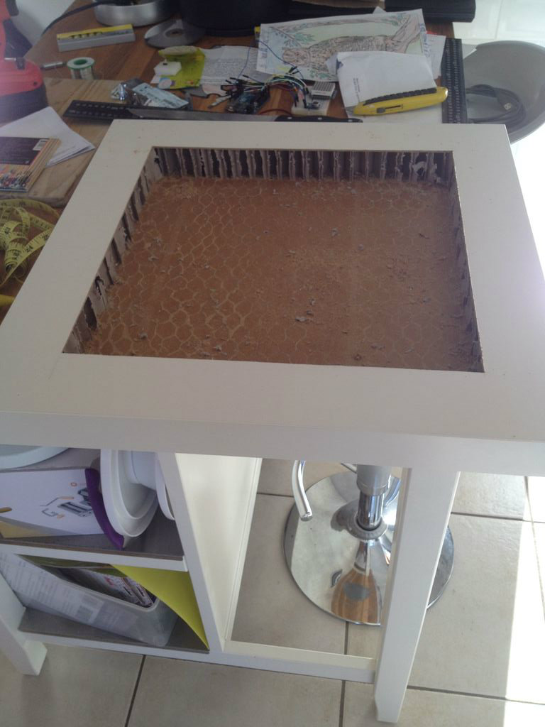
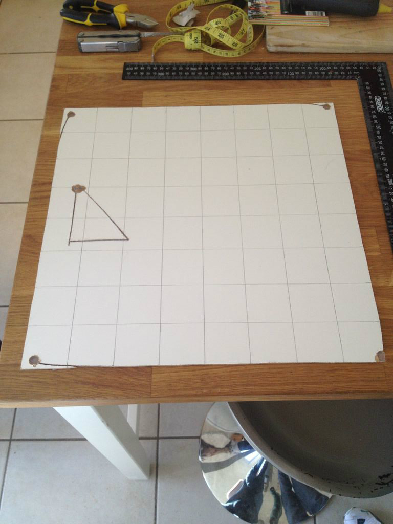
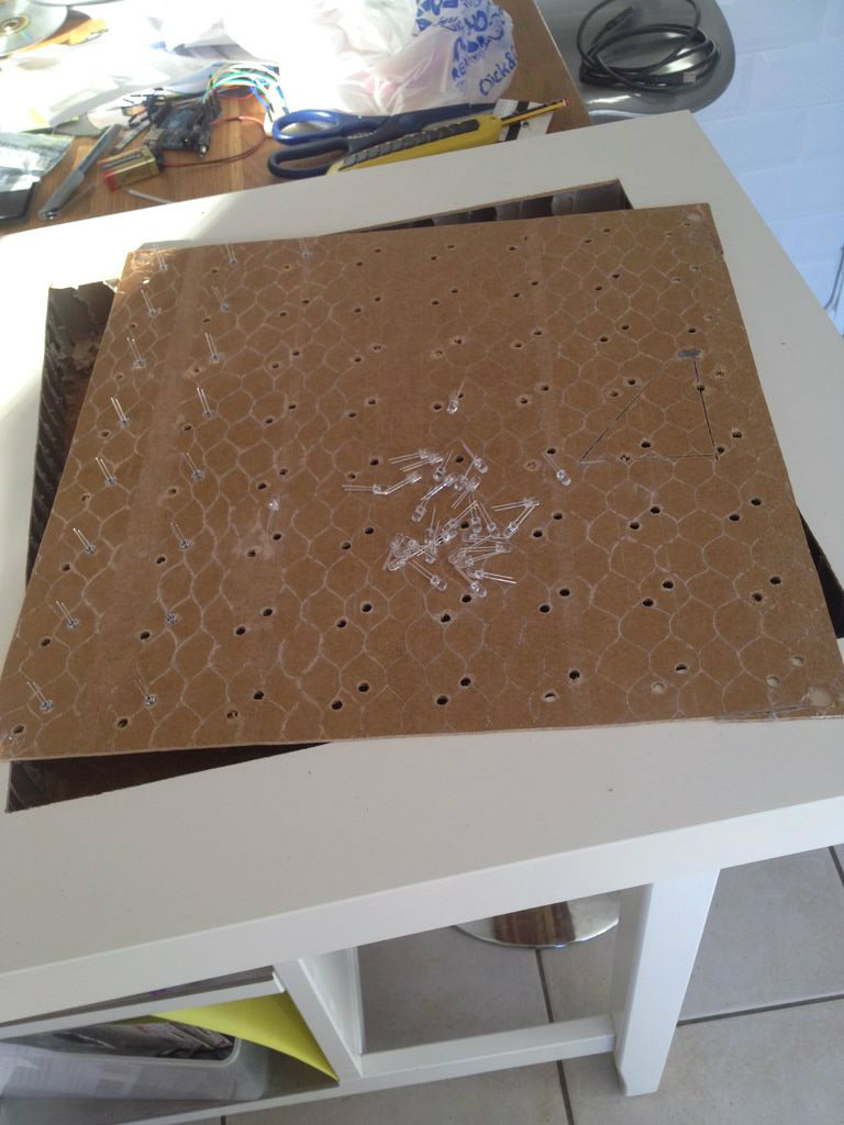
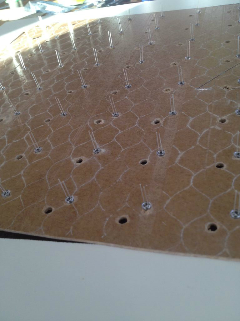
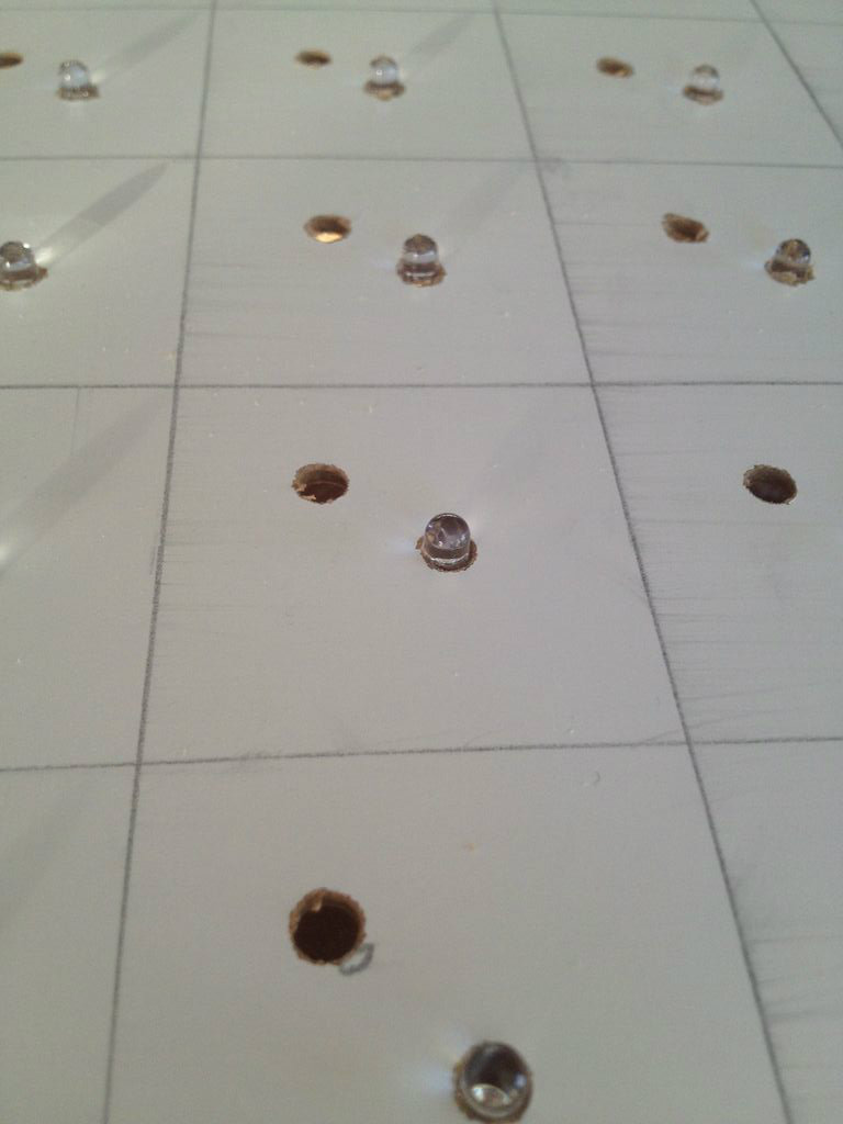
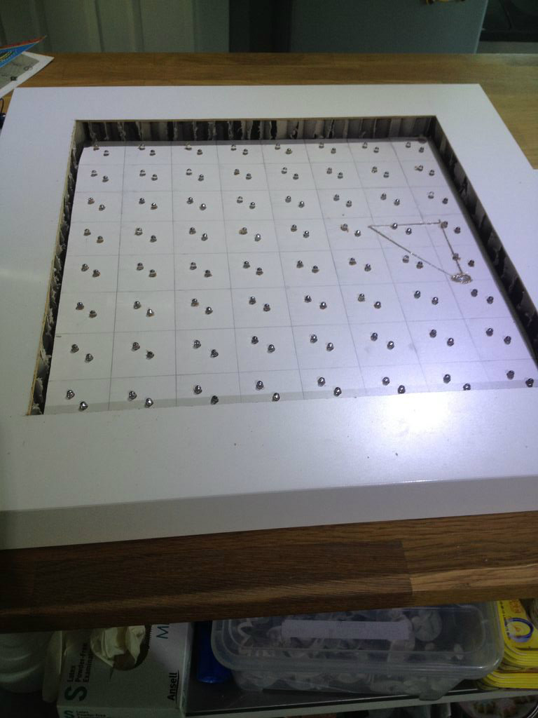
Having cut the hole, I sectioned off the white square I'd just cut out.
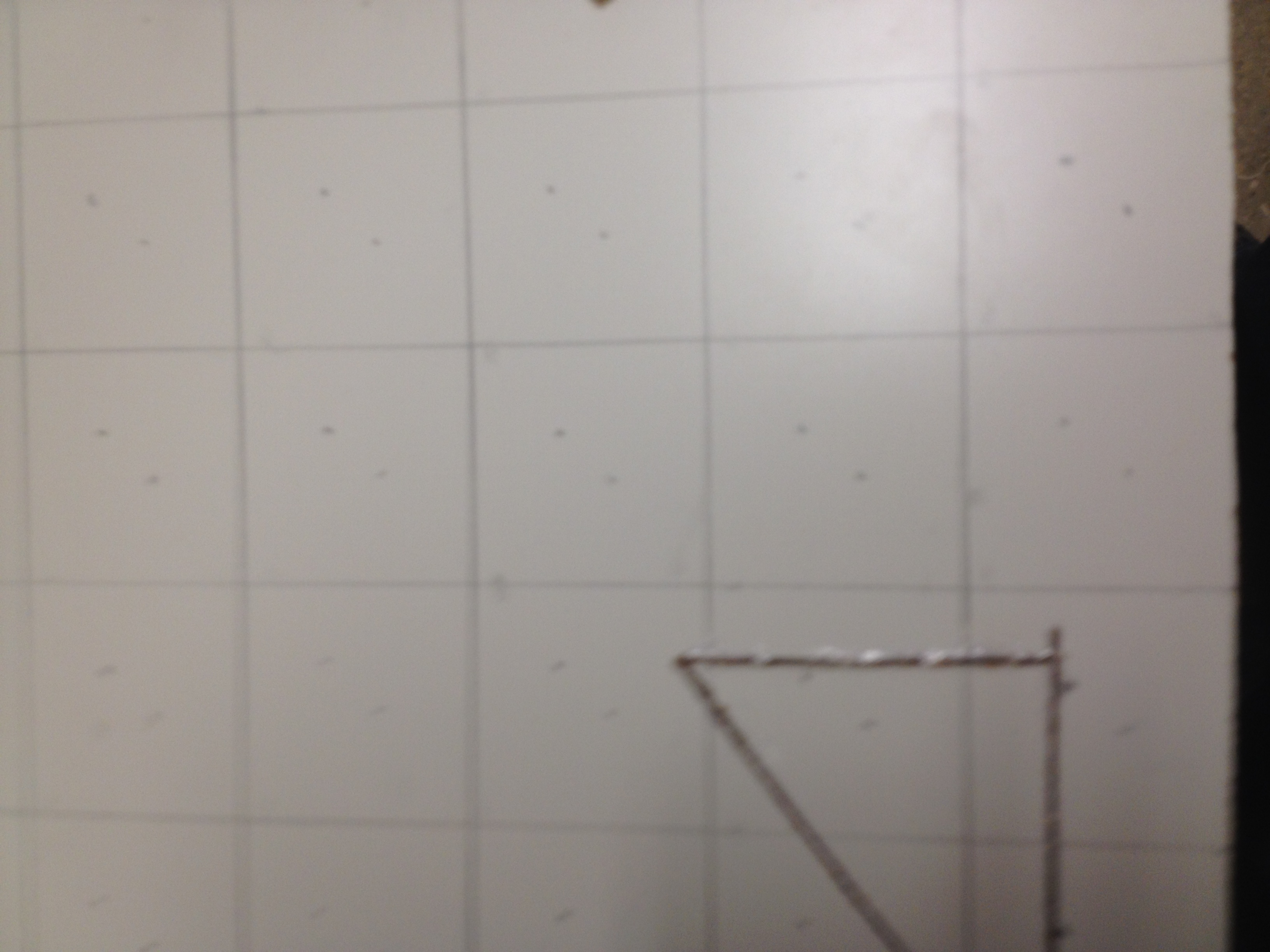
I then glued the triangle I'd cut back in place. Oops.
Then section off the board into 5cm2 pieces.
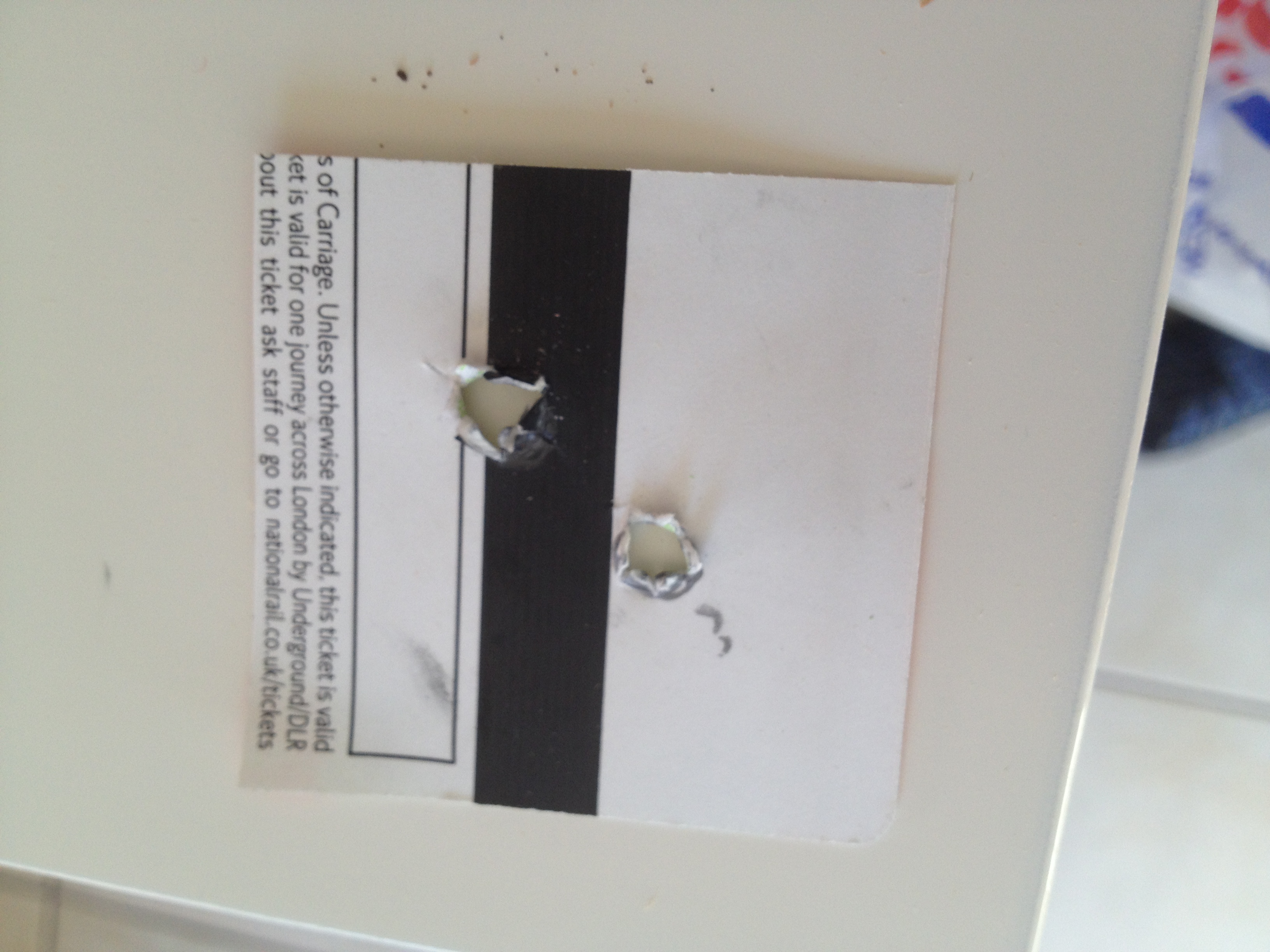
I made template for the led holes- yes it's an old rail ticket, and marked the holes.
Drill loads of holes and fill with leds.
Take a picture with all the leds in place. Feel good about what you've done.
Making the Matrix Grid
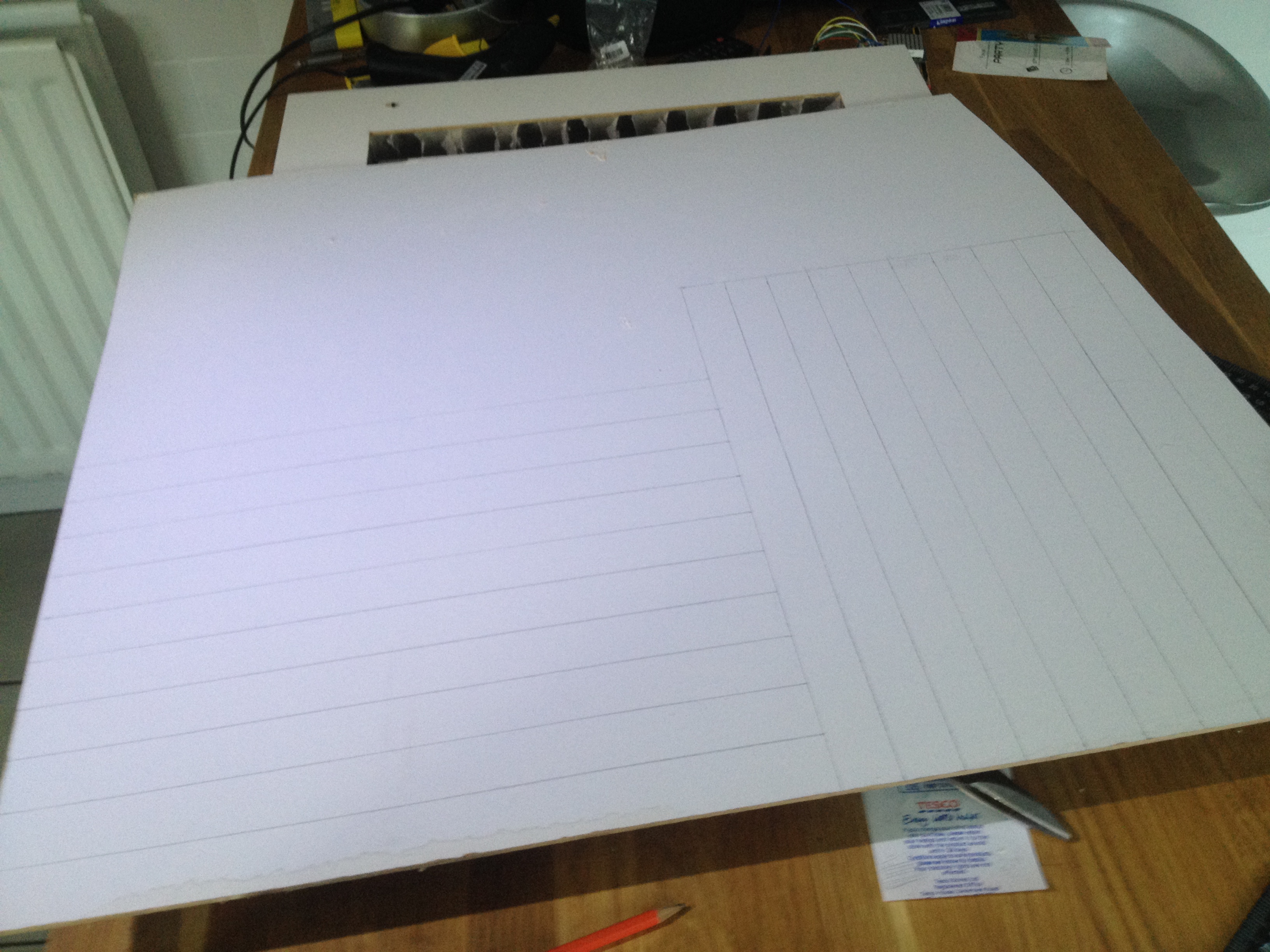
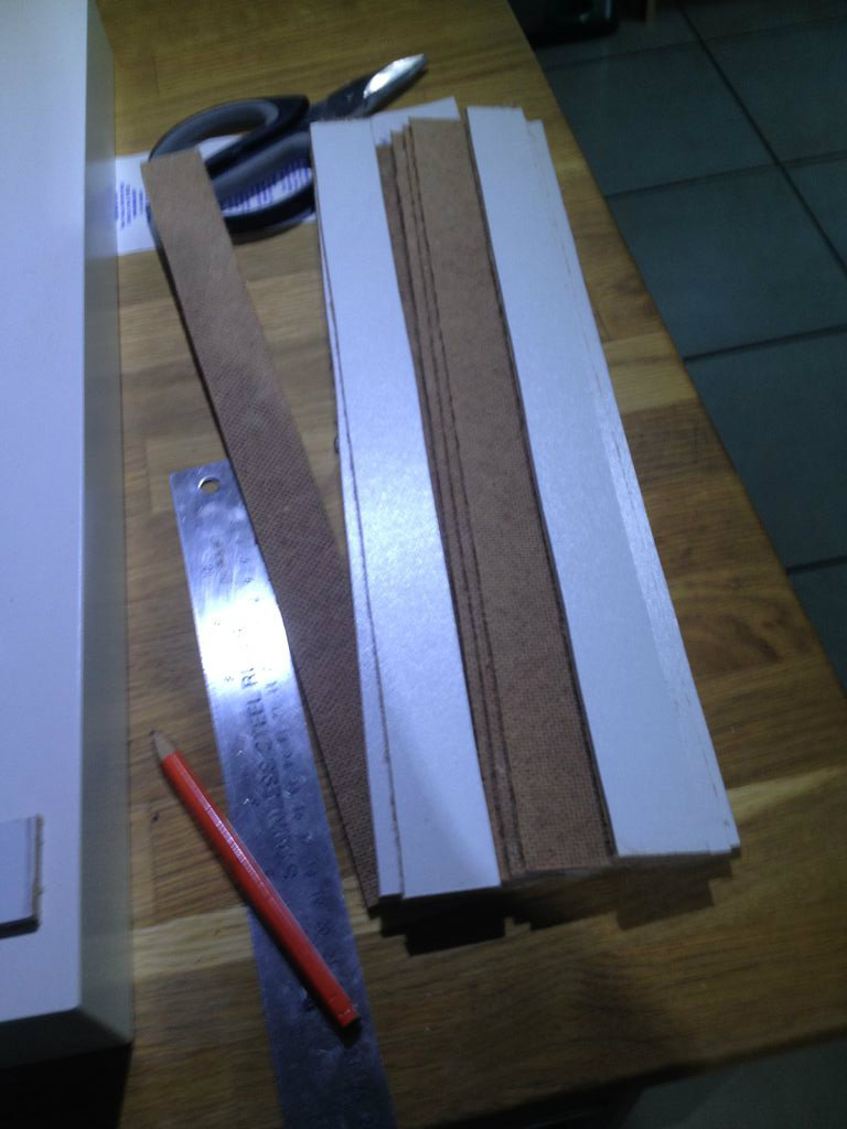
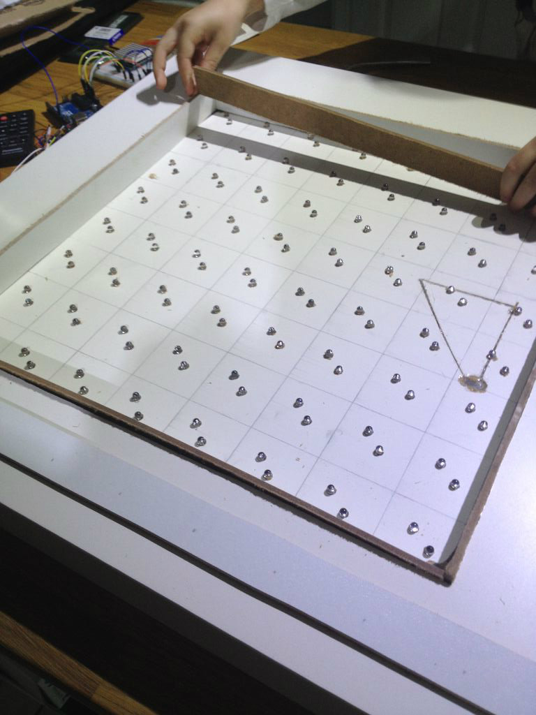
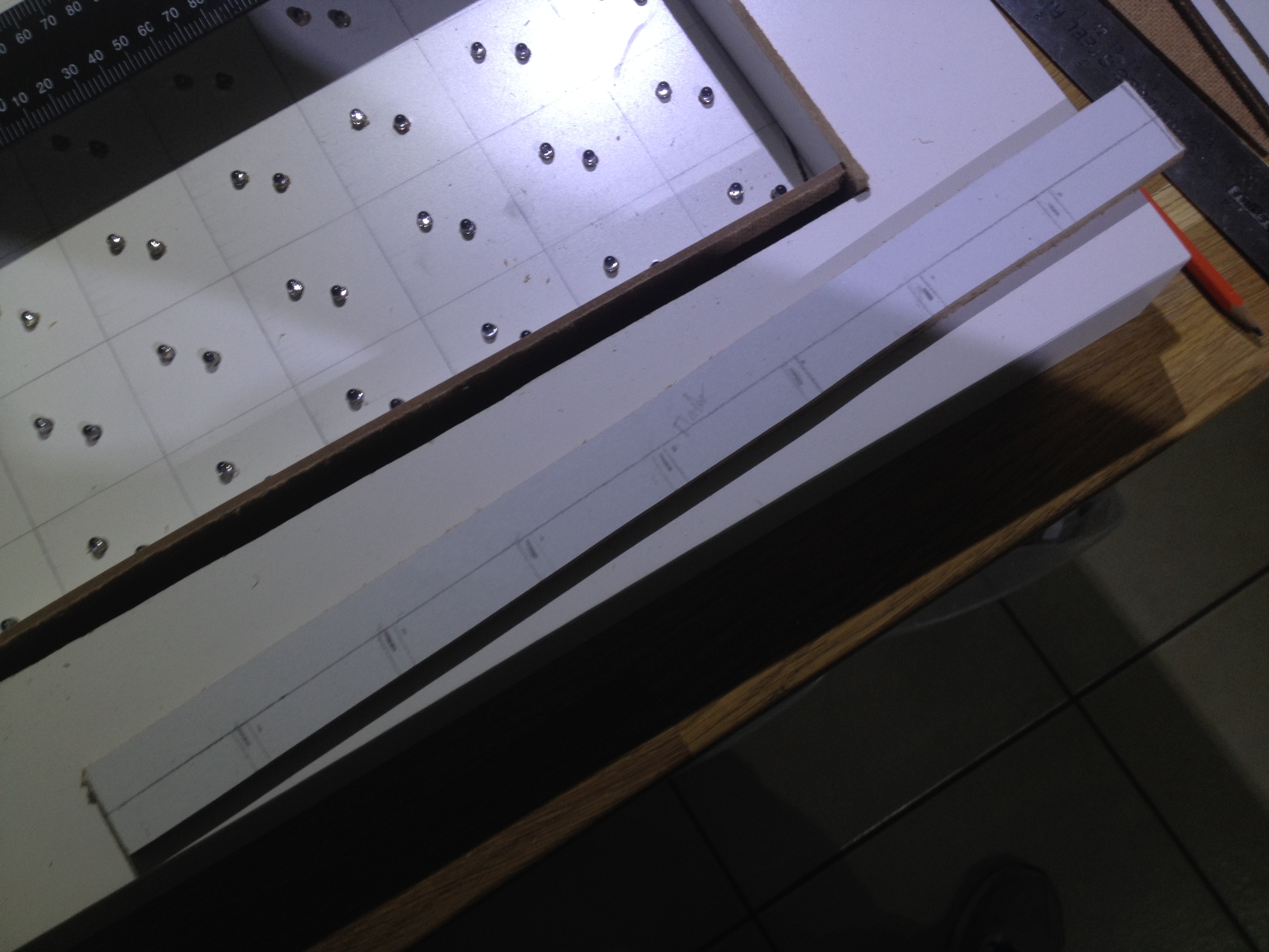
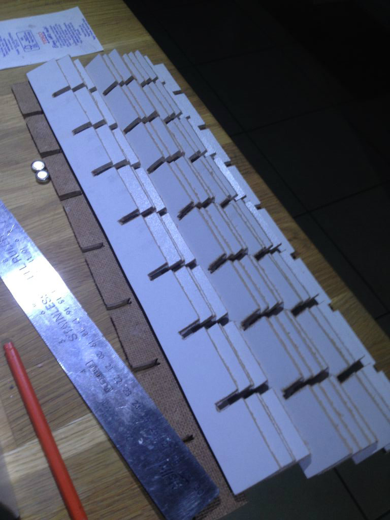
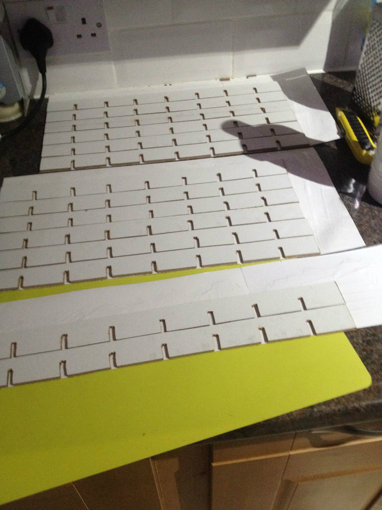
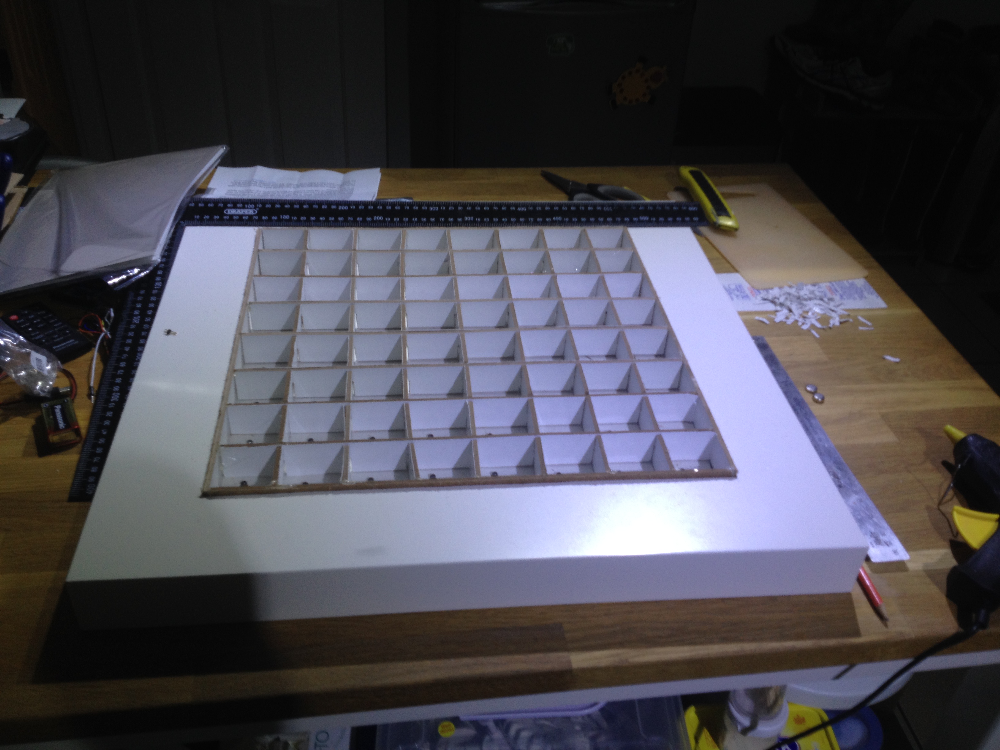
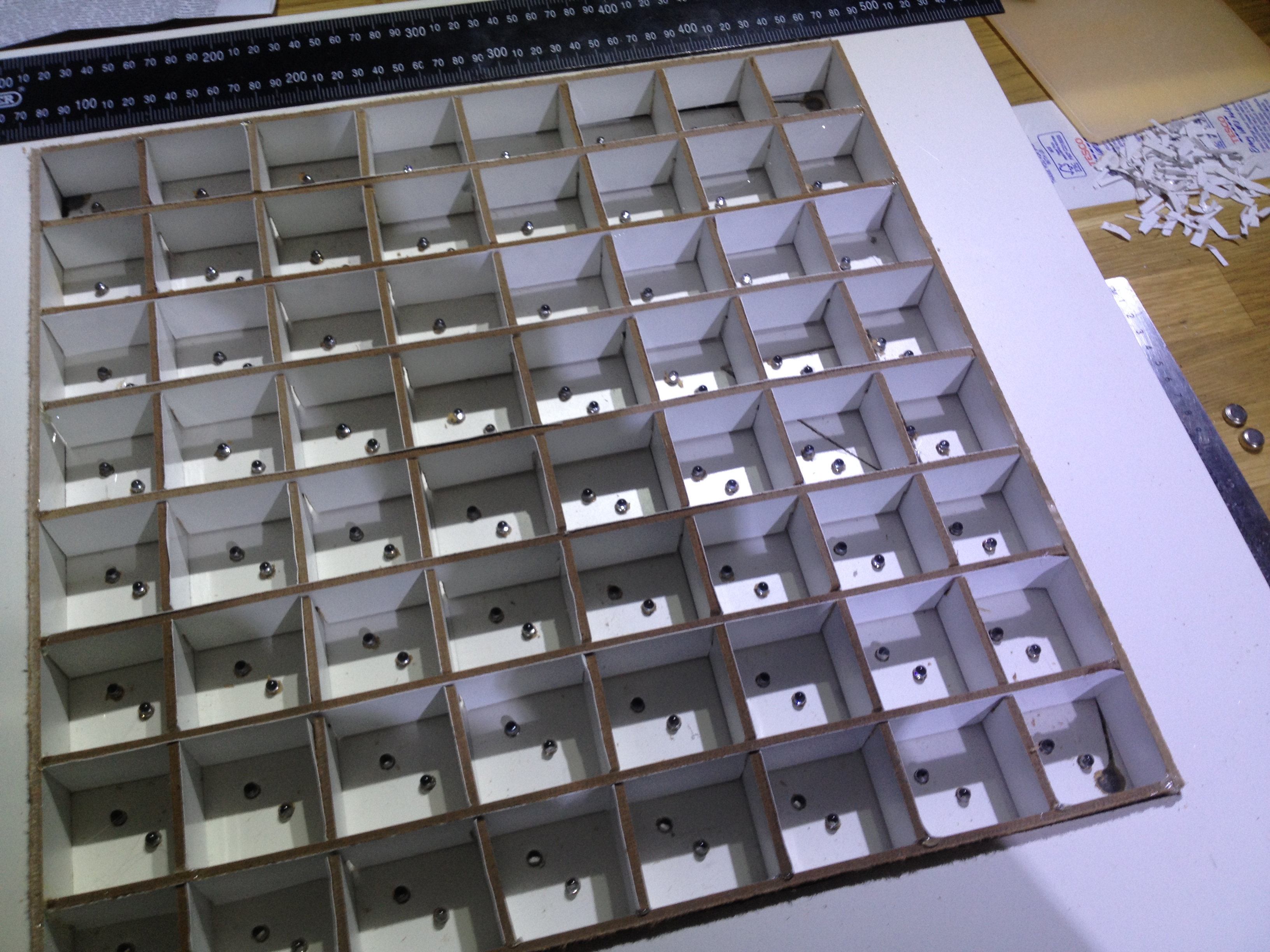
I got some white laminated hardboard I found in the garage and cut strips. The height was based on the depth of the table. There weren't measurements - it was done by eye.
I then used the bandsaw to cut the intersection holes. I then used the kids 'gloopy glue' (pva!), to stick reflective photopaper to the other side of the hardboard. I used a craft knife to cut this to size once dry.
I assembled the pieces and glue-gunned them into place.
Creating the Led Matrix
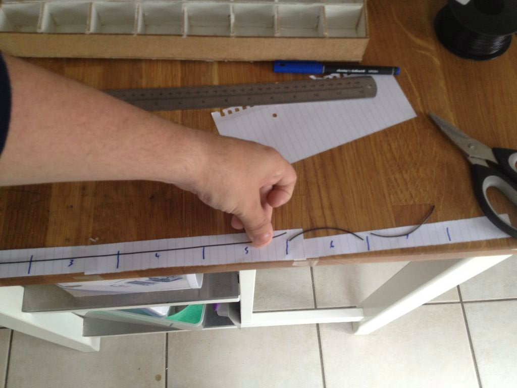
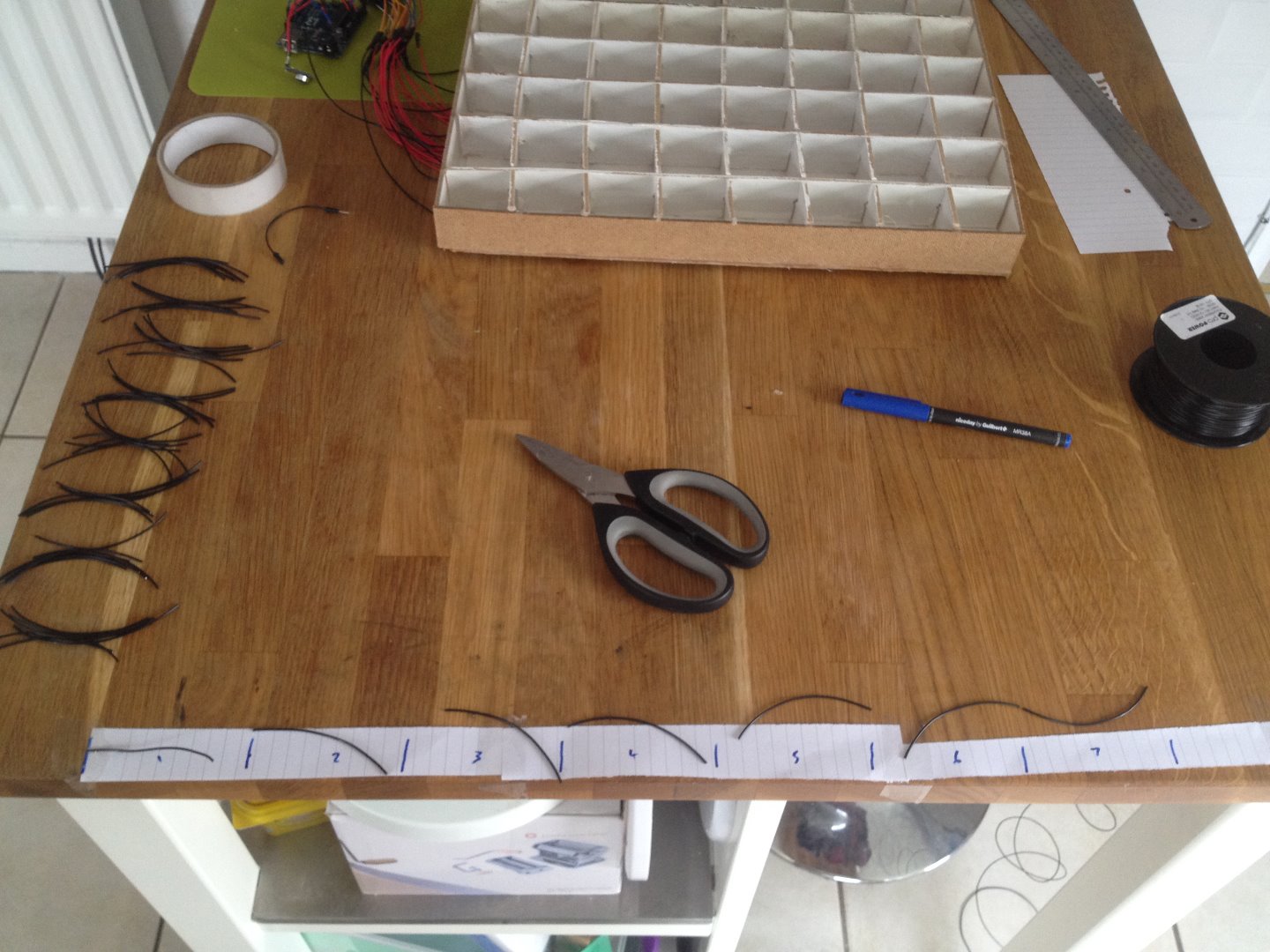
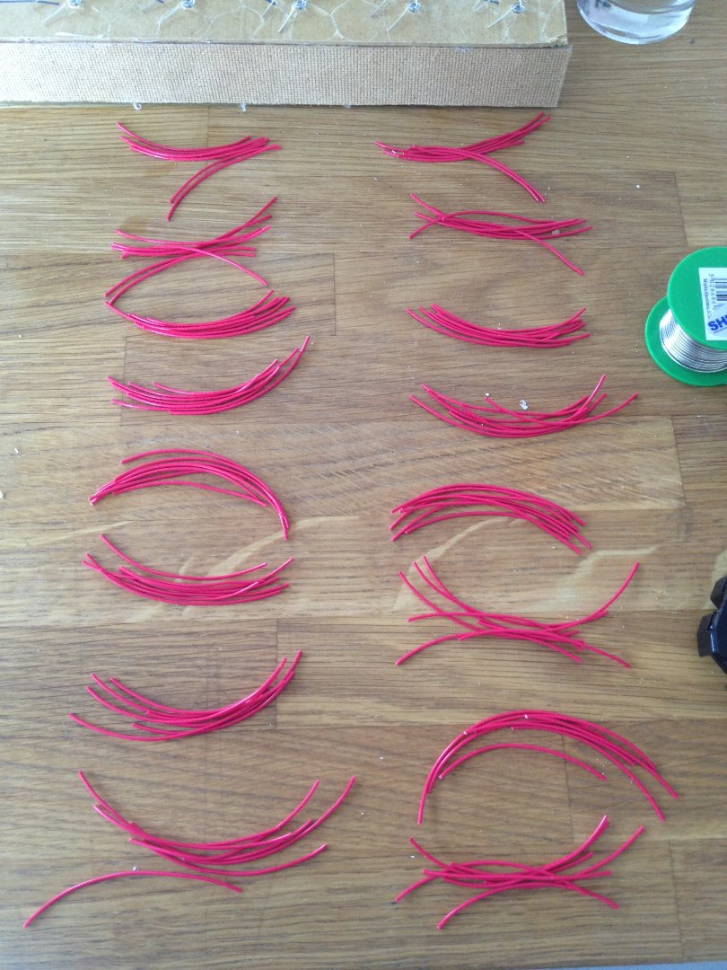
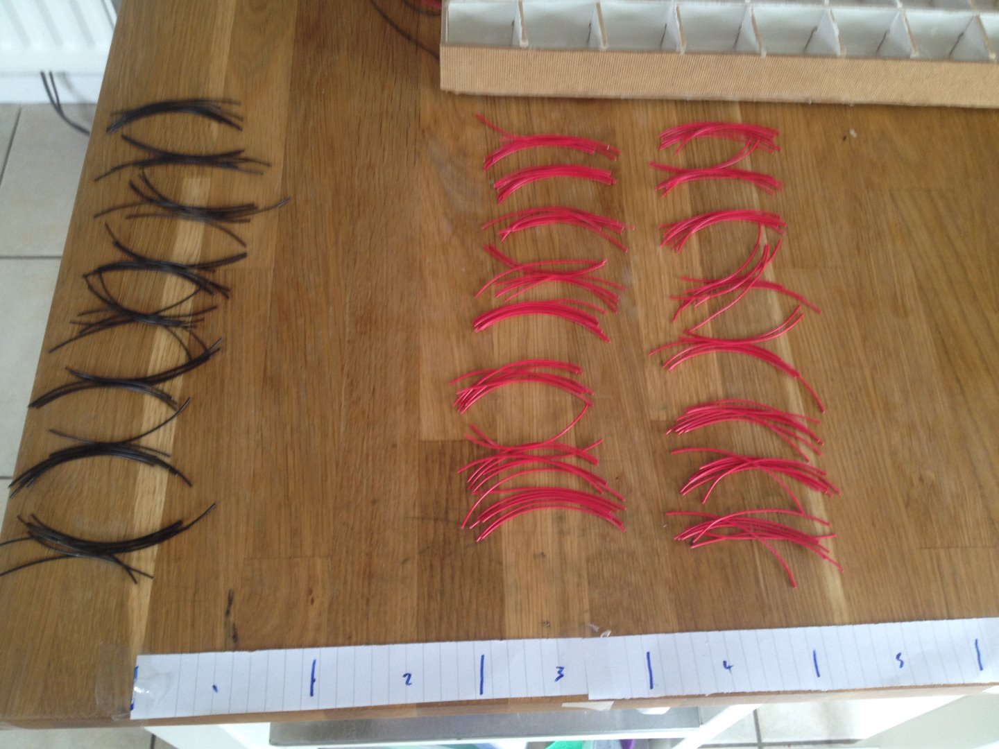
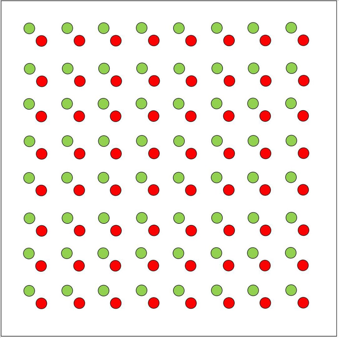
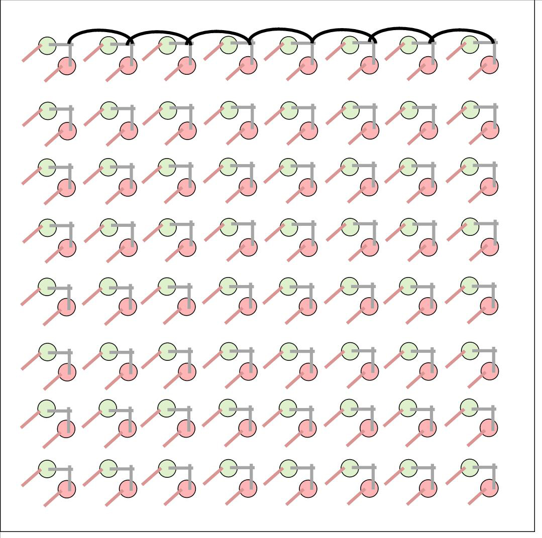
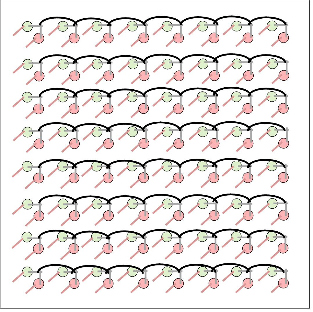
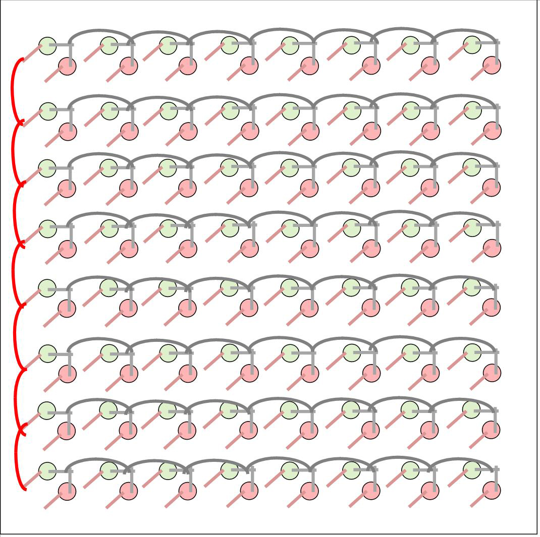
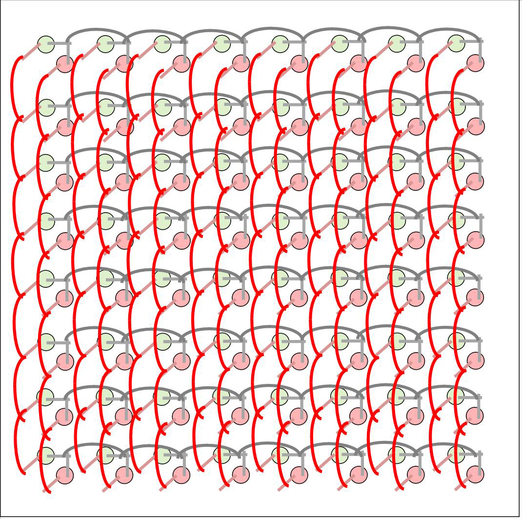
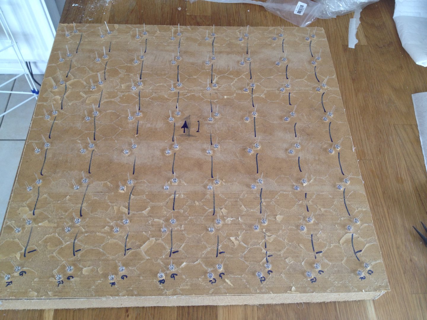
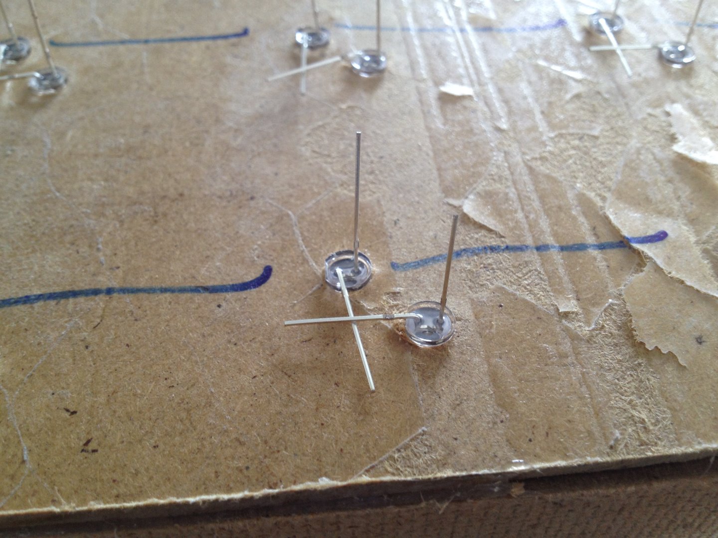
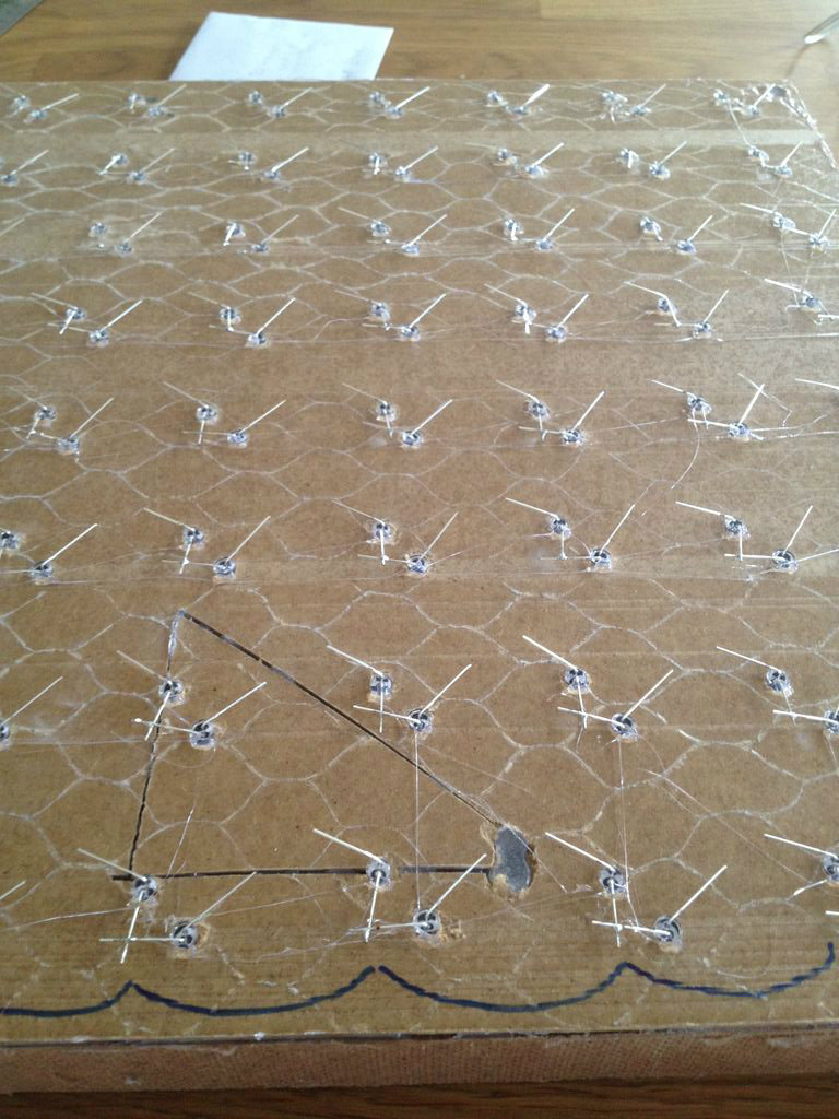
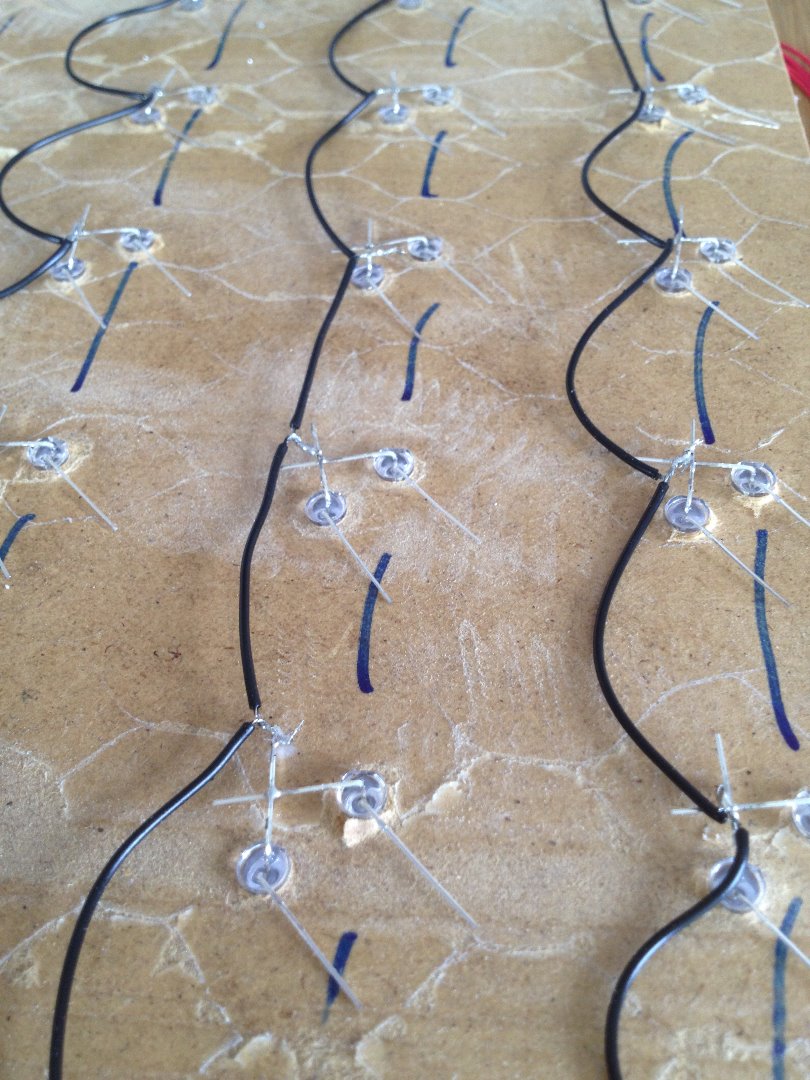
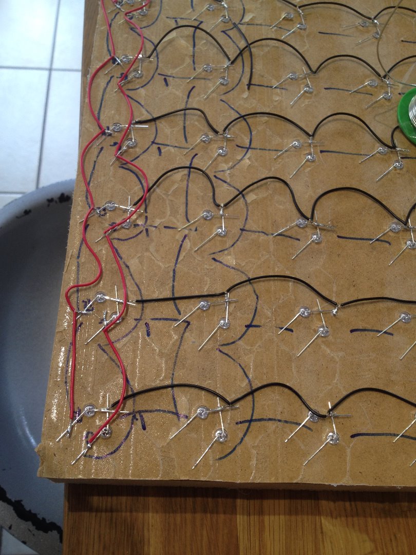
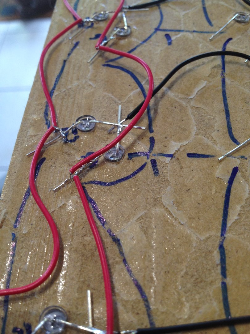
This is making a very large version of the common cathode matrix found in the attached datasheet.
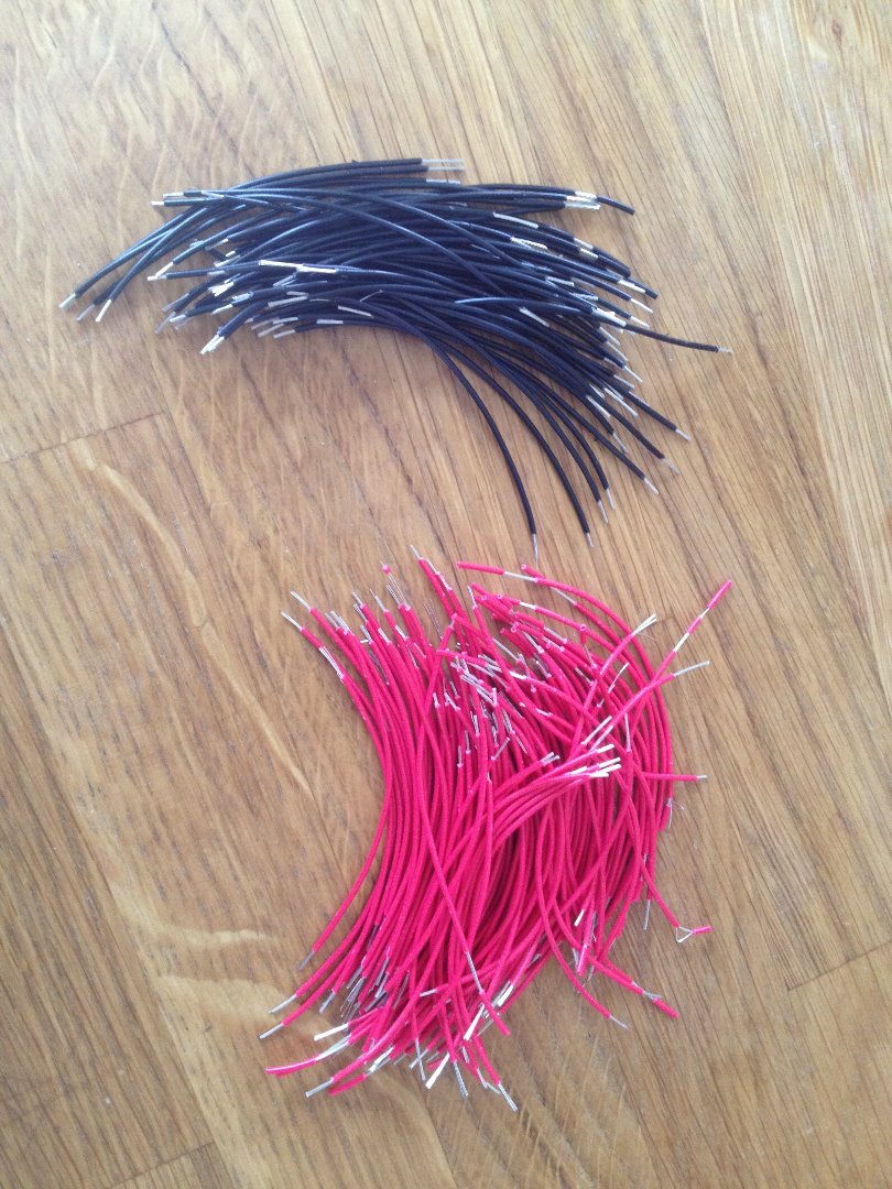
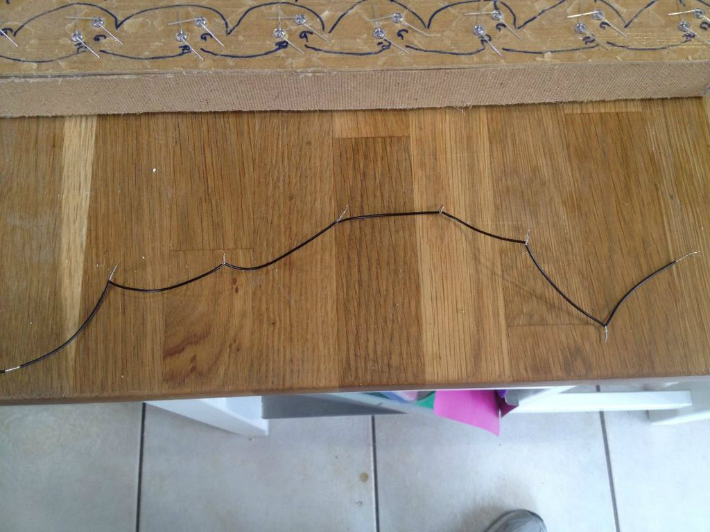
Firstly, cut some wires, and strip them, lots of them - I suggest you buy a wire stripper, I did and it made it so much easier! Once you think you've got enough, cut some more! You'll need 56 black wires and 112 red wires. Each should be about 7 to 8 cm long, but this will vary depending on your array, so just check before you cut all of them. As you'll see in one of the first pictures, I placed a marked piece of paper on my table, laid the wire along it and cut it into strips. This made the pieces the same length.
Next, to save my fat fingers whilst soldering, I twisted the wires into lengths of 7 pieces of wire - this was so I could solder the wires without trying to hold multiple wires at once.
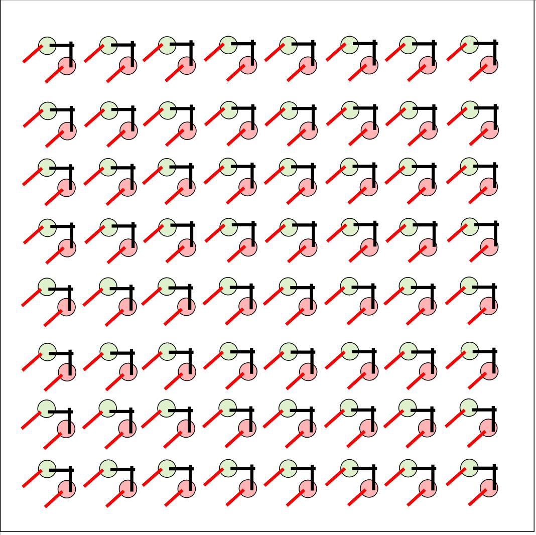
*** to make the next bit slightly clearer, I've added some diagrams that should highlight which wires are connecting where***
Having made the board with the holes,
Insert the LEDs in the back-side of the board and bend the legs over so the cathodes touch, but the anodes are separate.
Solder all the cathodes together using the black wires.
Solder all the anodes together using the red wires.
Downloads
Connecting the Circuitry
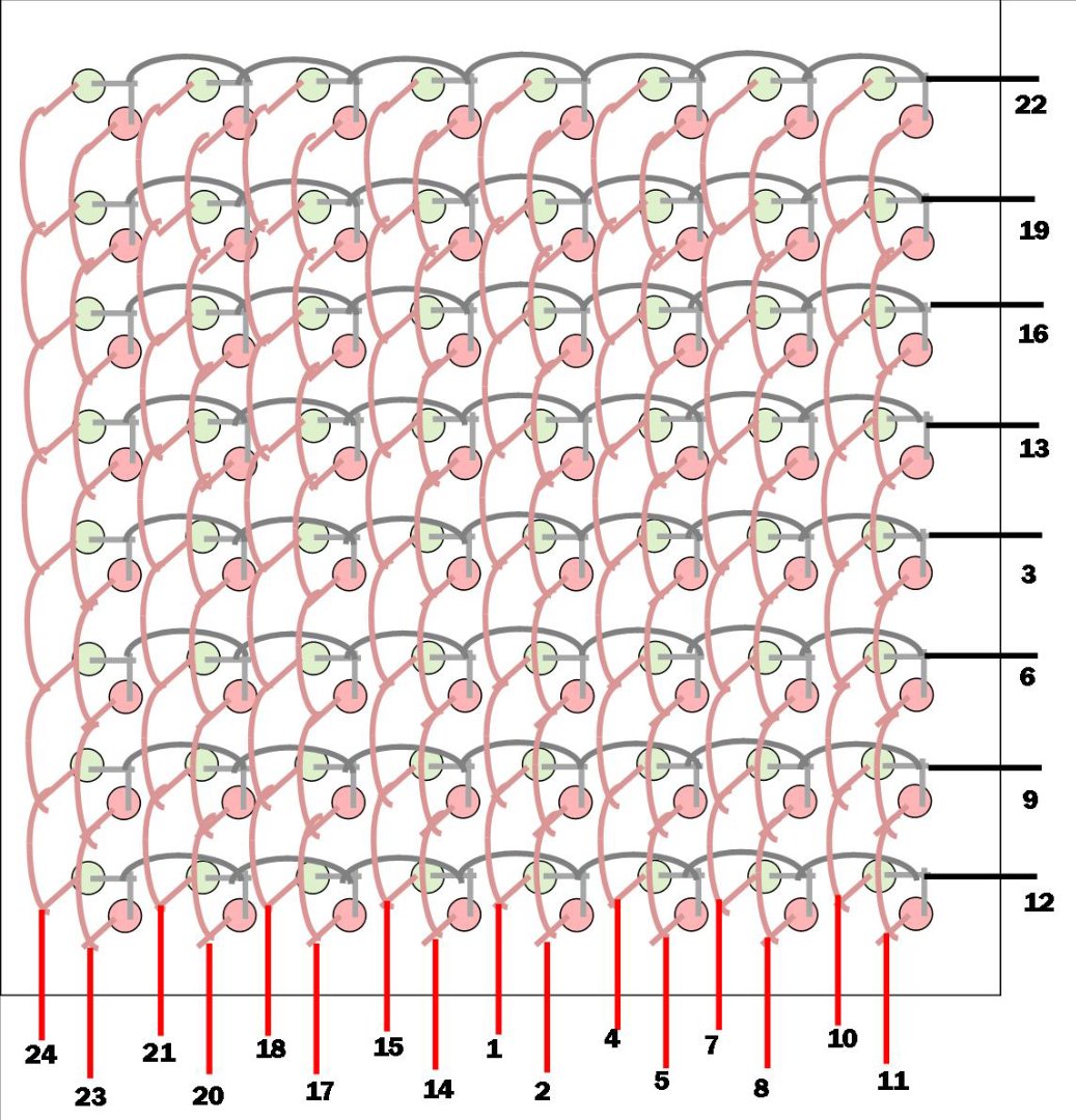
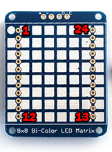
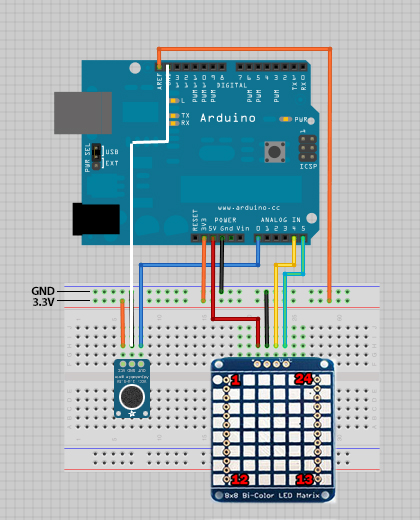
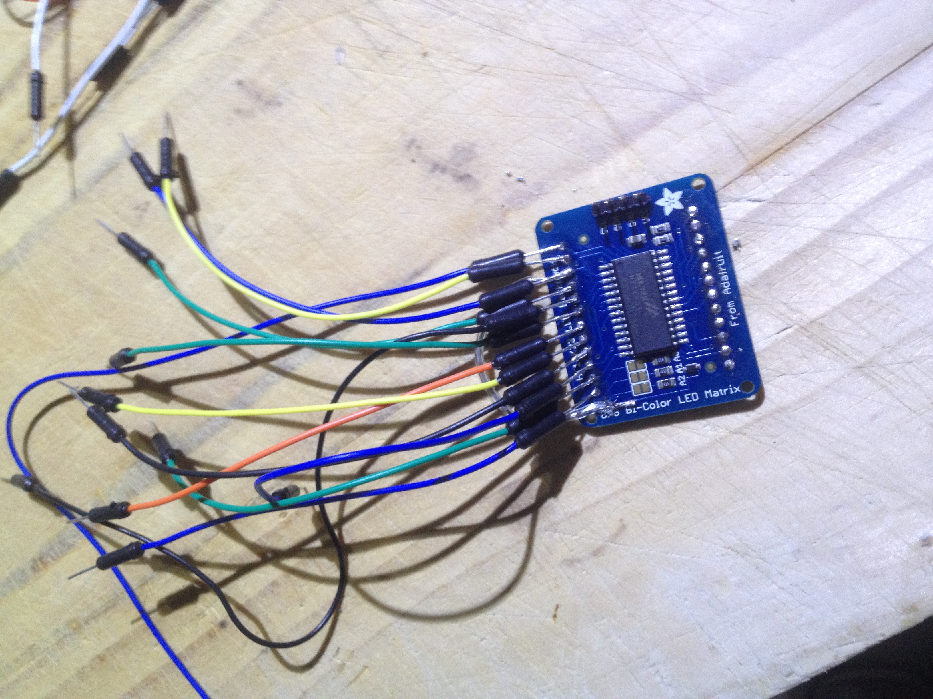
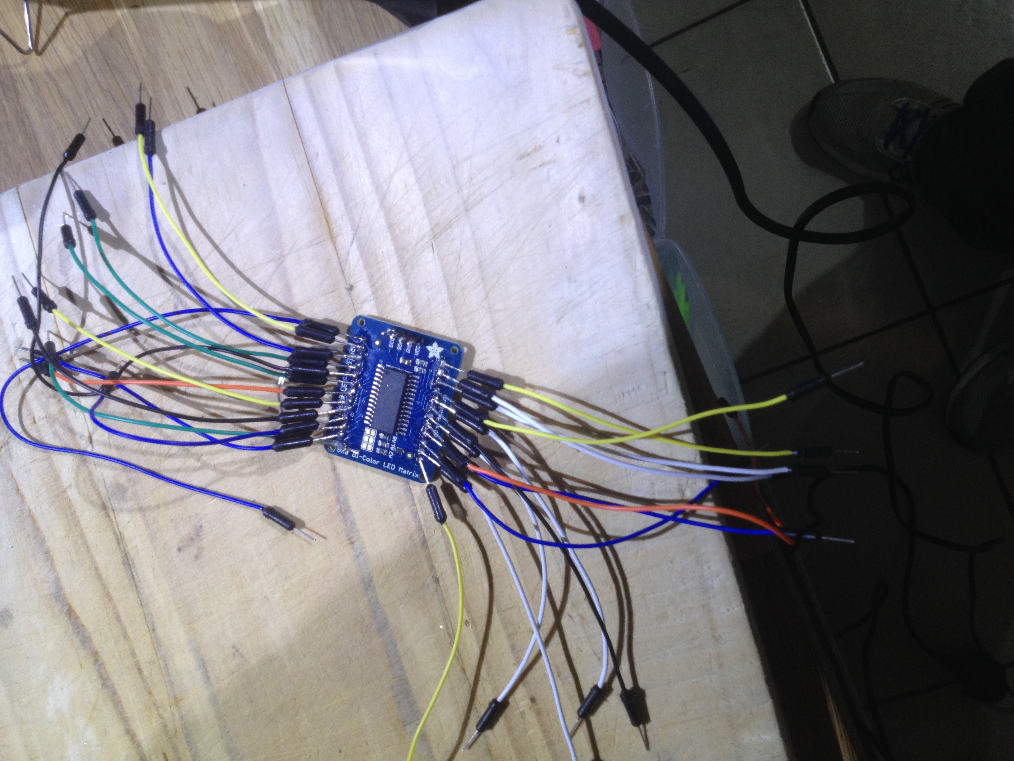
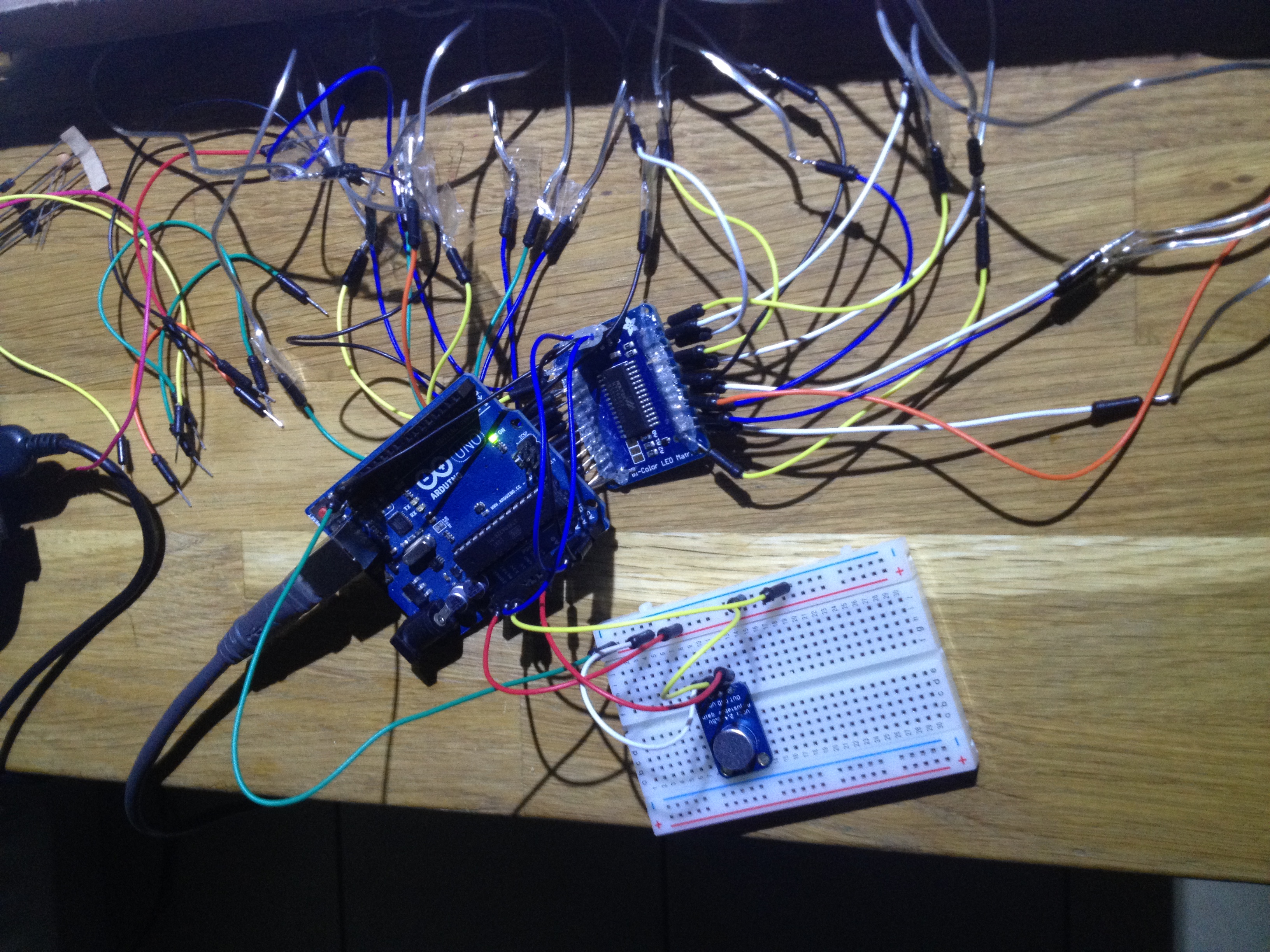
Connect your newly created array as the diagrams show.
The pins on the matrix connect directly to the circuit board. I've put the pinout on the board so you can see which pins are which.
I've also shown the circuit diagram that has come from Adafruit, but I've made one change - the GND connection from the microphone goes to a different GND connection than the LED array. I found that the microphone output was getting 'corrupted' if it was connected to the same GND and the output of the LED array was garbage.
Test the matrix and circuit as in the video.
https://www.youtube.com/watch?v=FUJ8XGJDLFY
Complete the Table
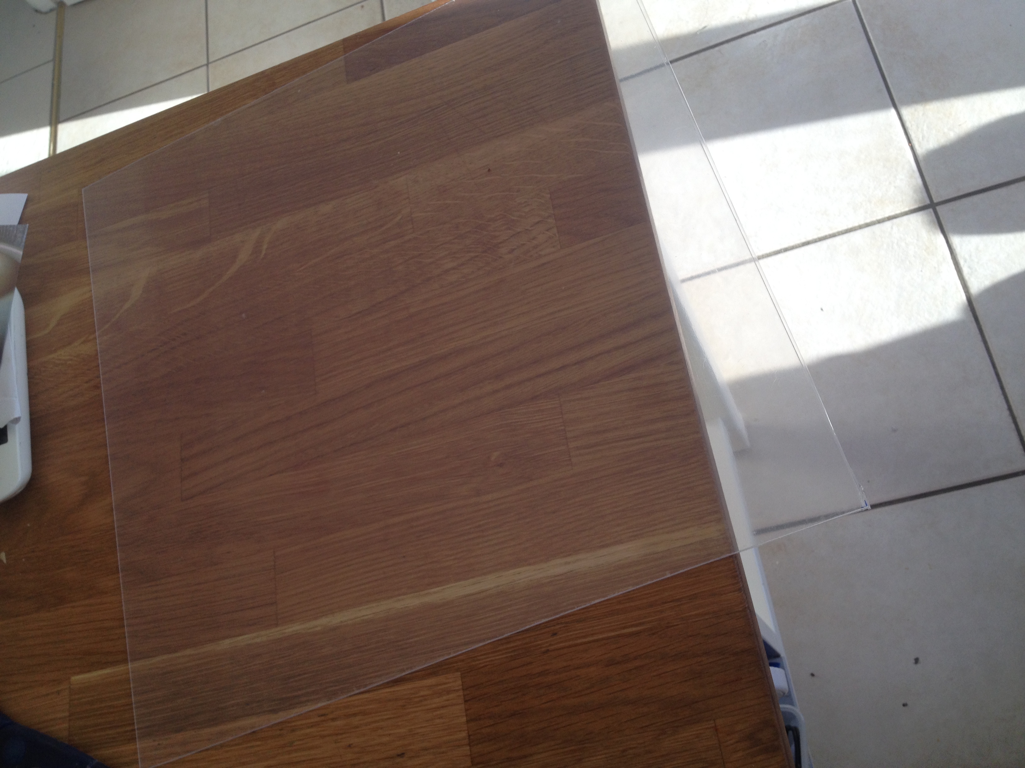
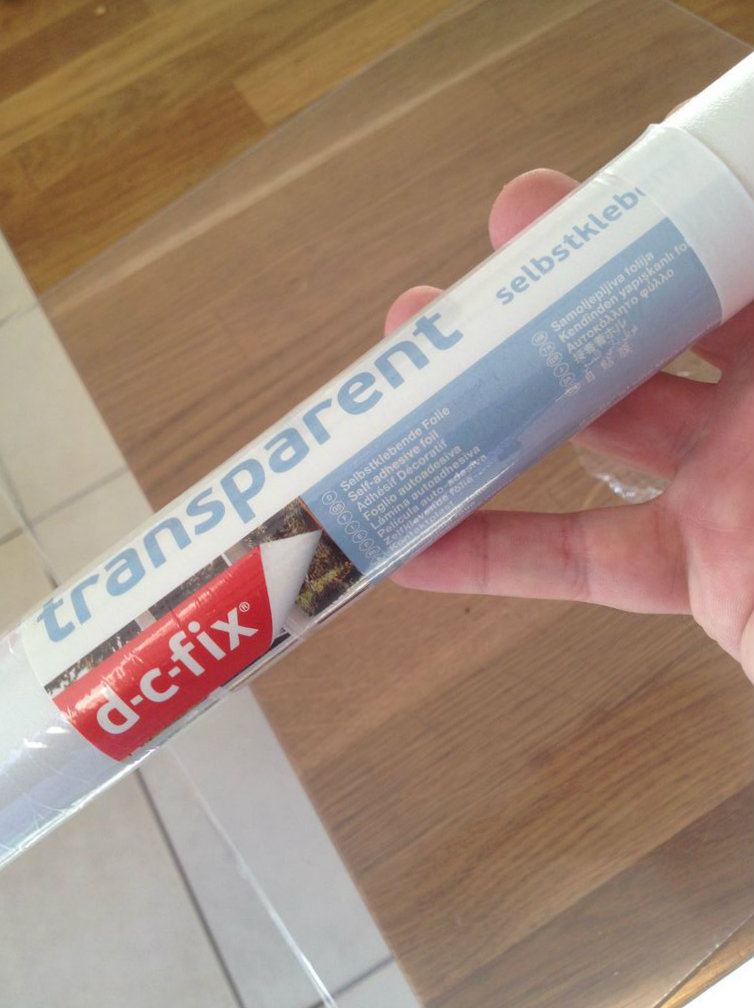
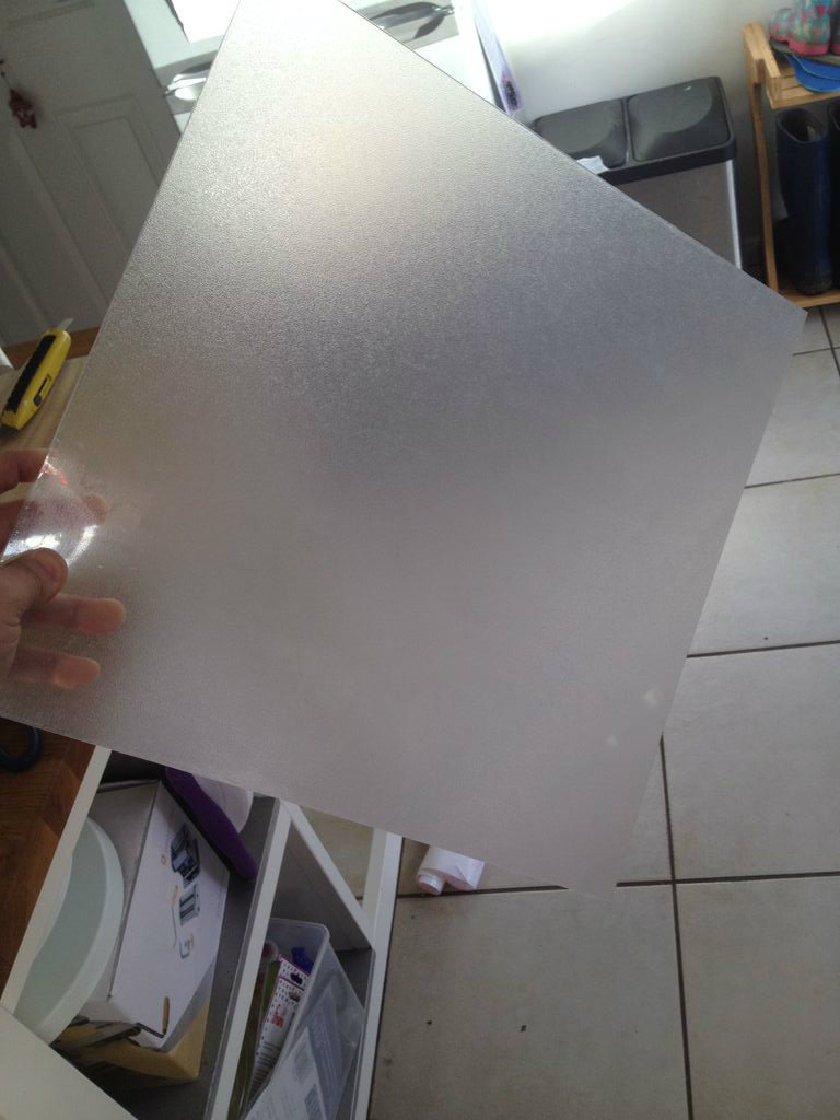
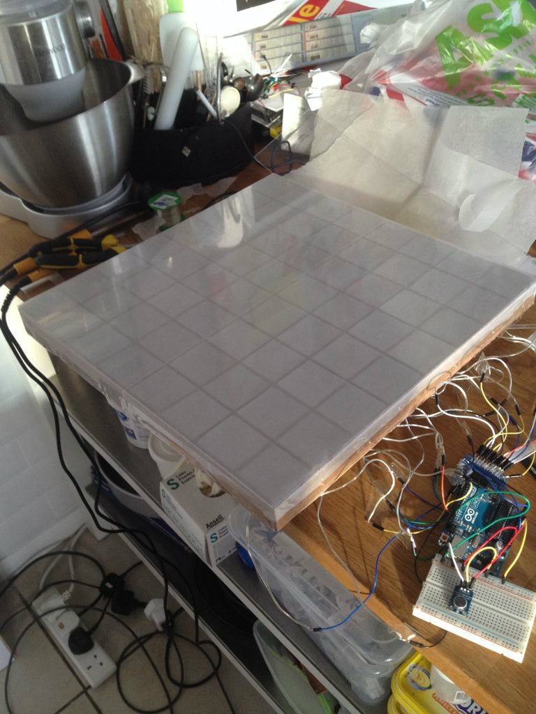
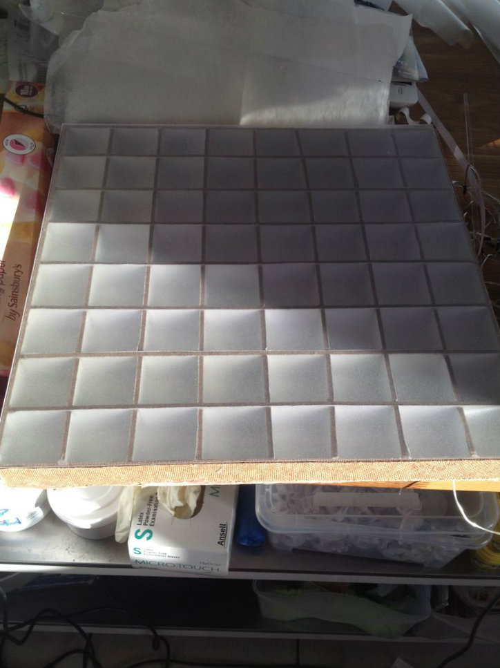
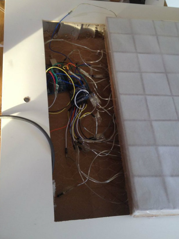
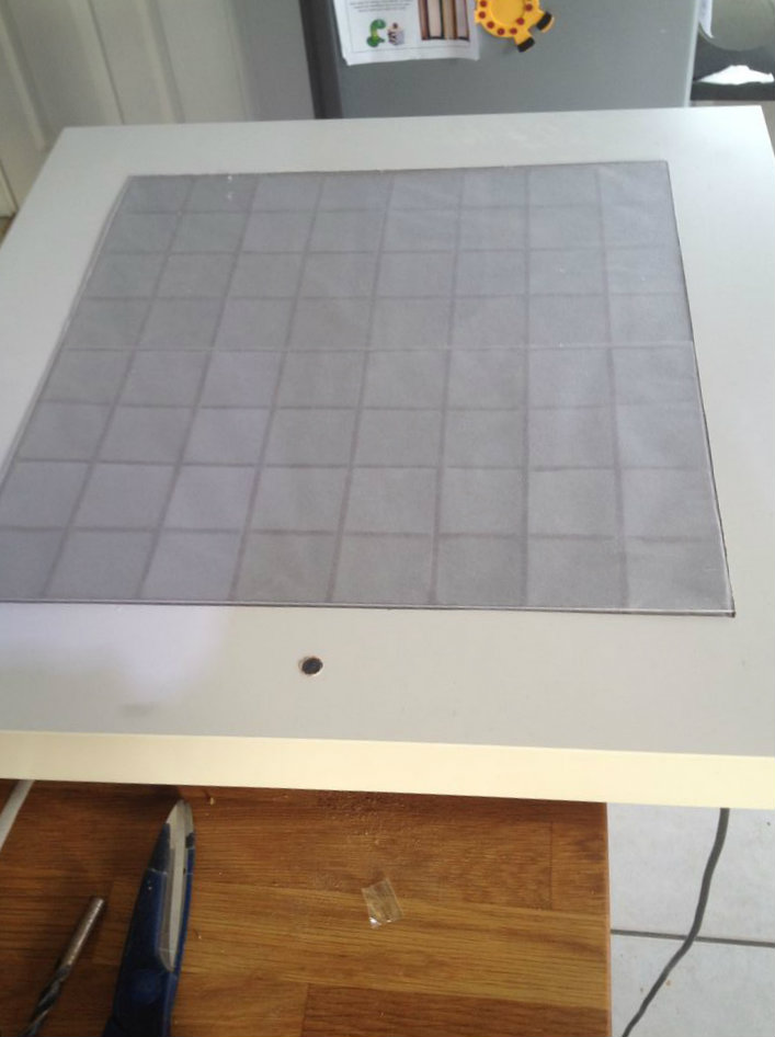
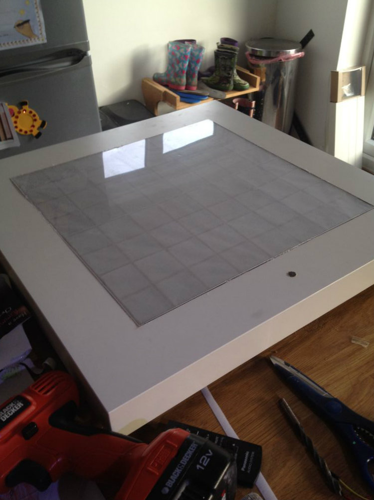
Get a piece of perspex the same size as the matrix, and cover it in frosted window film. If you can find pre frosted perspex then this may save you some effort. For added diffusion, I used some greaseproof paper as well.
I cut a hole in the bottom of the table to allow a usb cable to fit through.
Slide the matrix into place.
Glue to plastic top in place.
Your table is now complete.