Multiplexing Made Easy With the MM74C925N
by mastergabe in Circuits > Arduino
5430 Views, 109 Favorites, 0 Comments
Multiplexing Made Easy With the MM74C925N

I often find myself using seven segment displays in my projects, as they possess a retro look. Not only do i like using them but i also like making them. Through my encounters with seven segment displays i have learnt the many ways to control them with Arduino.
- Controlling each LED separately (extremely inefficient, with 4 displays it uses 28 outputs)
- Multiplexing (Efficient, but annoying to code)
- Shift registers (Easy to code, but uses a shift register per display)
These are probably the ones most people are familiar with, I personally used the shift register method until i found the MM74C925N. One day whilst making a purchase of LED's from my favourite LED supplier (led sales), I noticed they were selling a chip labeled as a "4-digit counter with multiplexed 7-segment display output drivers" this immediately sparked my interest and I bought 4 of them considering they were only $1.6 AUD. When I received them I got on my computer and looked up some tutorials on how to use them with Arduino, but I found nothing. I typed the chips name into the search engine but all i found was data sheets. Finally after reading a couple data sheets and looking at the schematic of a project some one had built 30 yrs ago, I worked out how i could use the MM74C925N with Arduino. This is how!!
My Findings

If you just wan't to find out how to use the MM74C925N skip this step.
As a high school student, and not an electrical engineer, the data sheets I read didn't make a lot of sense, but what i did gather from them was two things. Firstly the pin outs on the chip and secondly that it should be used with a common cathode seven segment display.
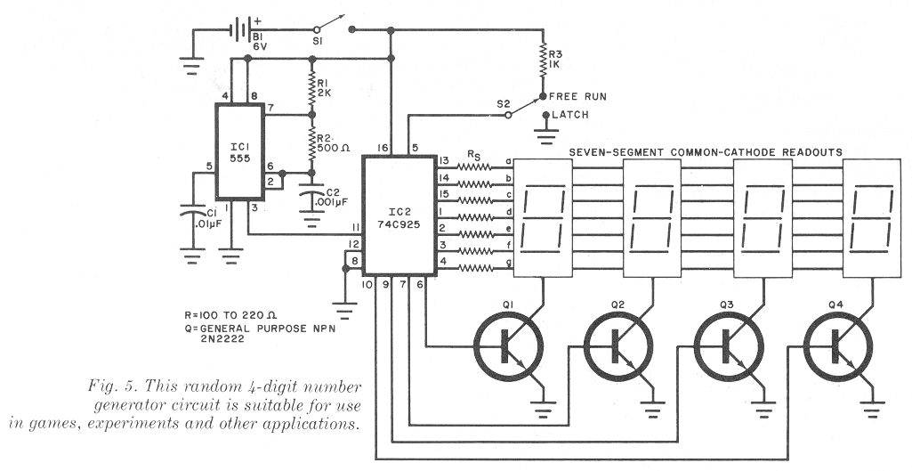
After searching google images I found a schematic of a random number generator. The first thing i noticed was that the clock pin was attached to an output pin on a 555 timer, from previous projects i remembered the 555 timers output an on and off signal. After looking a little more i discovered that for the displays to work properly there common cathodes must be wired to general purpose NPN transistors, controlled by the chip.
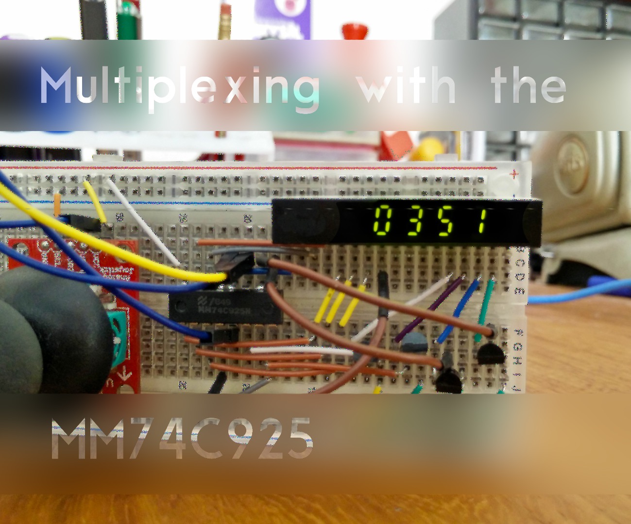
From this gathered knowledge I began to experiment. I wired everything up on my breadbord like this;
A segments - A on the chip (pin 13)
B segments - B on the chip (pin 14)
C segments - C on the chip (pin 15)
D segments - D on the chip (pin 1)
E segments - E on the chip (pin 2)
F segments - F on the chip - (pin 3)
G segments - G on the chip - (pin 4)
Base of Transistor 1 - outA on chip (pin 6)
Base of Transistor 2 - outB on chip (pin 7)
Base of Transistor 3 - outC on chip - (pin 9)
Base of Transistor 4 - outD on chip - pin 10
Latch pin (Pin 5) - GND
Reset pin (Pin 12) - GND
Clock pin (Pin 11) - Arduino Output Pin 13
GND (pin 8) - GND
Vcc (pin 16) - 5v+
The Collectors of all the transistors were attached to the common cathodes of each individual display and the emitters where grounded.
I started by programming the Arduino with a blink sketch to simulate the 555 and what I saw was that the display began to count. By connecting the reset pin to 5v the display would go back to zero and by connecting the latch pin to 5v the display hold its value, until the latch pin was grounded again and it would show the changes. After a bit of work i set up a library of my own to program the Arduino to use the MM74C925N in an easy way.
How to Use the MM74C925N With Arduino

The bit you've been waiting for, after a little bit of tinkering i finally worked out an efficient and easy way to program the Arduino to control the MM74C925N and heres how.
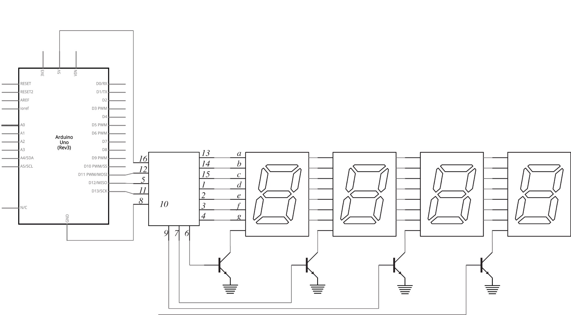
Wire everything up as shown in the schematic (if your 7 segment display is rated at a lower voltage then 5v i would recommend putting a 220Ω resistor between each anode and the chip, you can see this being done in the schematic on step 1).
Now once everything is wired up its time to program!
Programming

To make things easier i made a simple library, feel free to edit the library or make your own, but i definitely recommend you read the library to work out whats happening. In shorts when you choose a number the Arduino sets latch to high, resets the chip, and sends a rapid on and off signal until the chip counts up to the desired number.
To use the library, go into your Arduino folder and then into the library folder. Create a new folder and call it MM74C925N. Download the attached files and save them in this folder.
Open up the Arduino program goto Sketch, on the top bar, and then Include Library you should see MM74C925N down the button, select it. Now you need to create an instance of the class, to do this copy the text bellow
MM74C925N RandomName(ClockPin, LatchPin, ResetPin);
If you have wired it up according to the schematic in step 2 make sure you replace ClockPin with 13 LatchPin with 12 and ResetPin with 11, and RandomName with whatever name you want e.g. My7Seg.
Nothing needs to be put in the voids setup, so leave it blank.
finally in the void loop to print a number on the seven segment display write
RandomName.print(YourNumber);
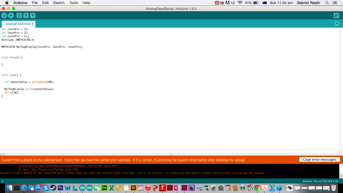
You can now use the MM74C925N in any code you want, as an example i have used a simple sensor code, attaching a sensor to A0 and printing its value on the seven segment display.
I hope you have enjoy my Instructable and gained insight into the MM74C925N, please vote and comment any queries.