MouseMorphia | Adaptive Mouse for Disabled Individuals
by j-skoobs in Circuits > Assistive Tech
2178 Views, 19 Favorites, 0 Comments
MouseMorphia | Adaptive Mouse for Disabled Individuals
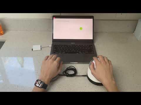
MouseMorphia is a specialized computer mouse crafted for individuals with limited fine motor controls. This innovative adaptive mouse repurposes old or unused computer mice, making use of cost-effective 3D-printing technology to enhance accessibility. By incorporating accessible left and right click buttons through a standard 3.5mm mono-jack, MouseMorphia offers customization options, allowing users to use buttons that are tailor-made, previously owned, or readily available for purchase.
Supplies
(Exact models not needed, recommended to use what you already have!)
Tools:
- 3D-Printer
- 3D-Printer Filament
- Soldering Iron
- Solder
- Desoldering pump
- Wire Stripper
- Small Philips Head screwdriver
Parts:
- Logitech M510 Wireless Mouse (Exact model needed)
- 3D-Printed mouse parts
- 3D-Printed button parts (2x required for 2 buttons)
- 3D Printed Mono Jacks x2 (+1 per button)
- 3.8" (~ 4") Foam Ball
- Paper clips
- Soft core copper wire (22 gauge recommended)
- 3.5mm Headphone Cable (2x required for 2 buttons)
Optional:
Testing Software
3D-Print Mouse Parts
No Supports:
3D-Print all parts using no supports!
Disassemble Logitech M510 Wireless Mouse
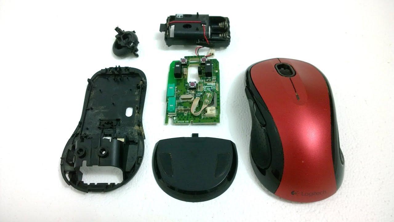
Desolder Mouse Clicks
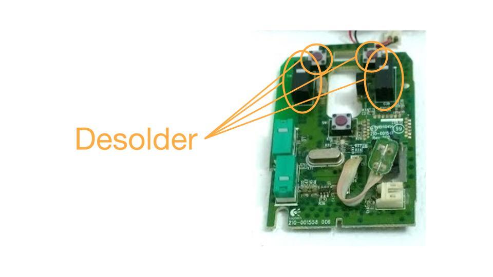
1. Desolder
Desolder each mouse button highlighted above.
2. Set Aside
Set aside all buttons for later.
3D-Print Mono Jacks
Mono Jack Paperclips
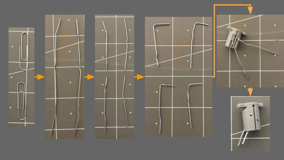
1. Straighten Paperclips:
Straighten two paperclips to remove any bends.
2. Cut Paperclips:
Cut each straightened paperclip in half, resulting in four equal parts.
3. Create Right Angles:
Bend a small right angle at one end of each cut paperclip.
4. Insert into Mono Jack:
Insert the short bent end of each paperclip into the designated slots on the 3D-Printed Mono Jack.
5. Adjust Length:
Cut the protruding end of each paperclip to a length of about 6mm, ensuring a proper fit within the Mono Jack.
Mono Jack Soldering
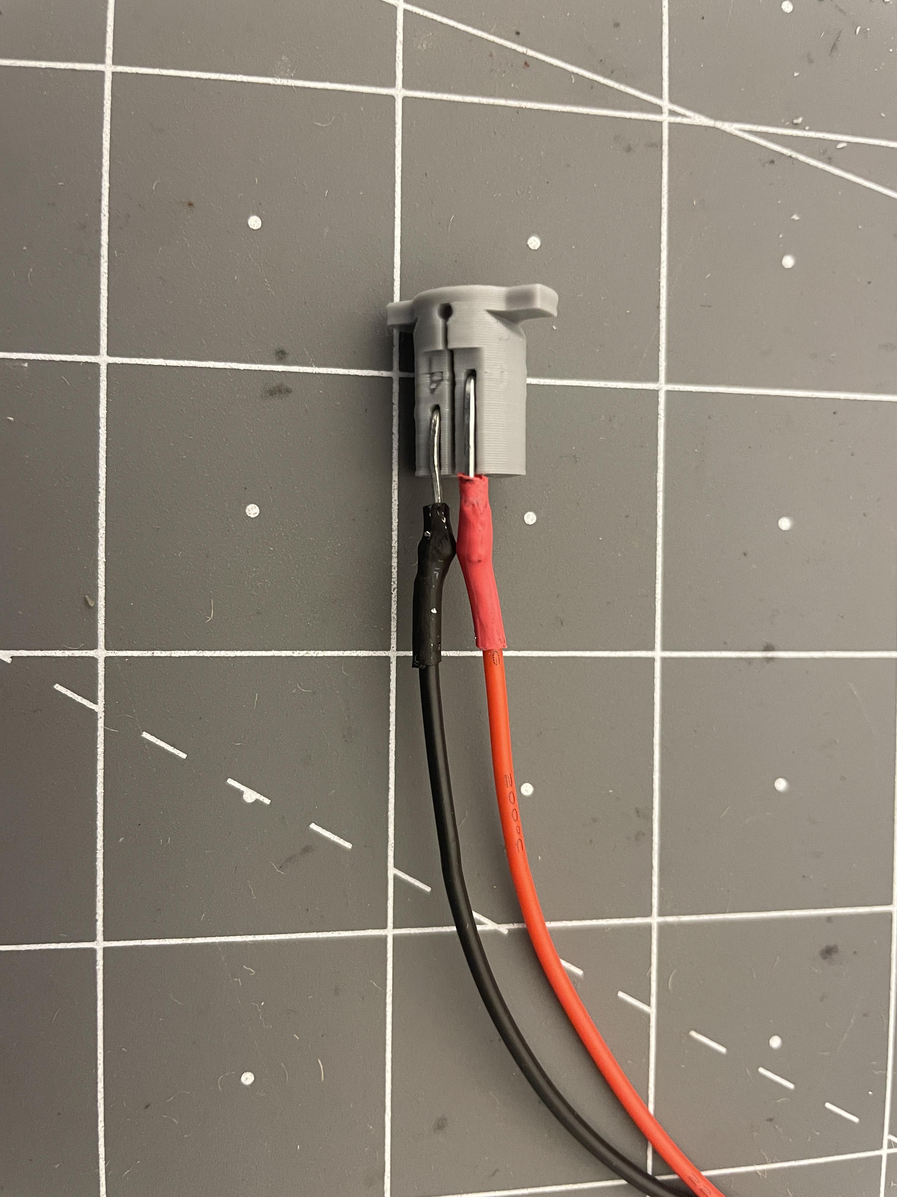
1. Prepare Materials:
Gather 22 Gauge wires, Mono Jack paperclips, soldering iron, solder, and optionally heat shrink tubing or hot glue.
2. Cut Wires:
Cut four 22 Gauge wires, each approximately 40mm in length.
3. Strip Wire Ends:
Strip the ends of each wire to expose the metal core.
4. Solder Wires to Mono Jacks:
Solder one end of each 22 Gauge wire to each of the holes on each Mono Jack paperclip. Note: the shorter hole is negative, and the longer one is positive.
5. Secure Joints (Optional):
Optionally, use heat shrink tubing or hot glue on the solder joints to enhance their strength and reliability.
6. Inspect Connections:
Ensure that the solder joints are secure and well-connected.
7. Repeat
Repeat steps 1-6 for all Mono Jacks.
Mounting Mono Jacks
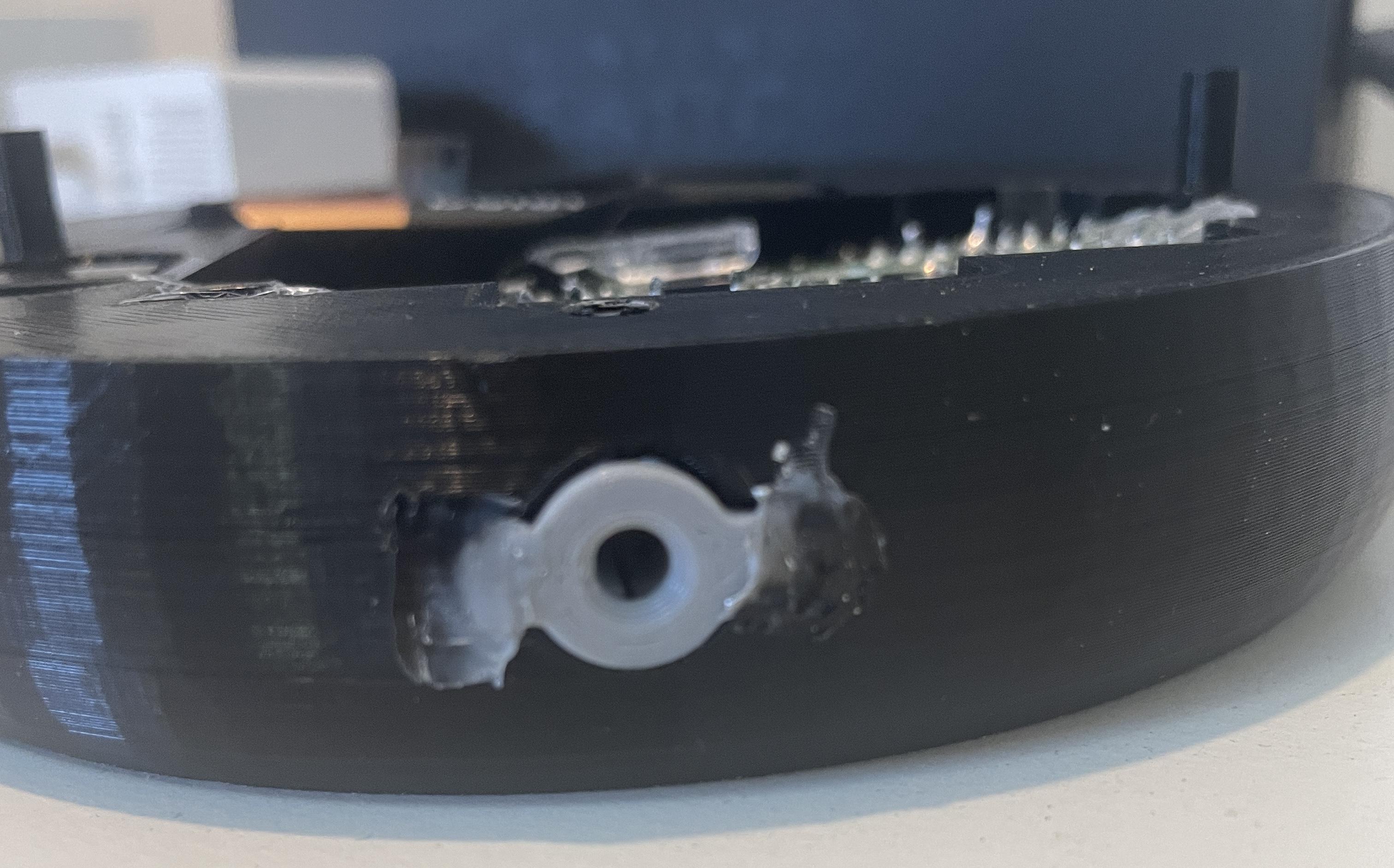
1. Guide Wires
Ensure wires are guided though the hole of the mouse base.
2. Melt Together
Use soldering iron to melt Mono Jack flanges into MouseMorphia base as shown above.
3. Repeat for opposite side
(Mouse only)
Mouse Motherboard Soldering
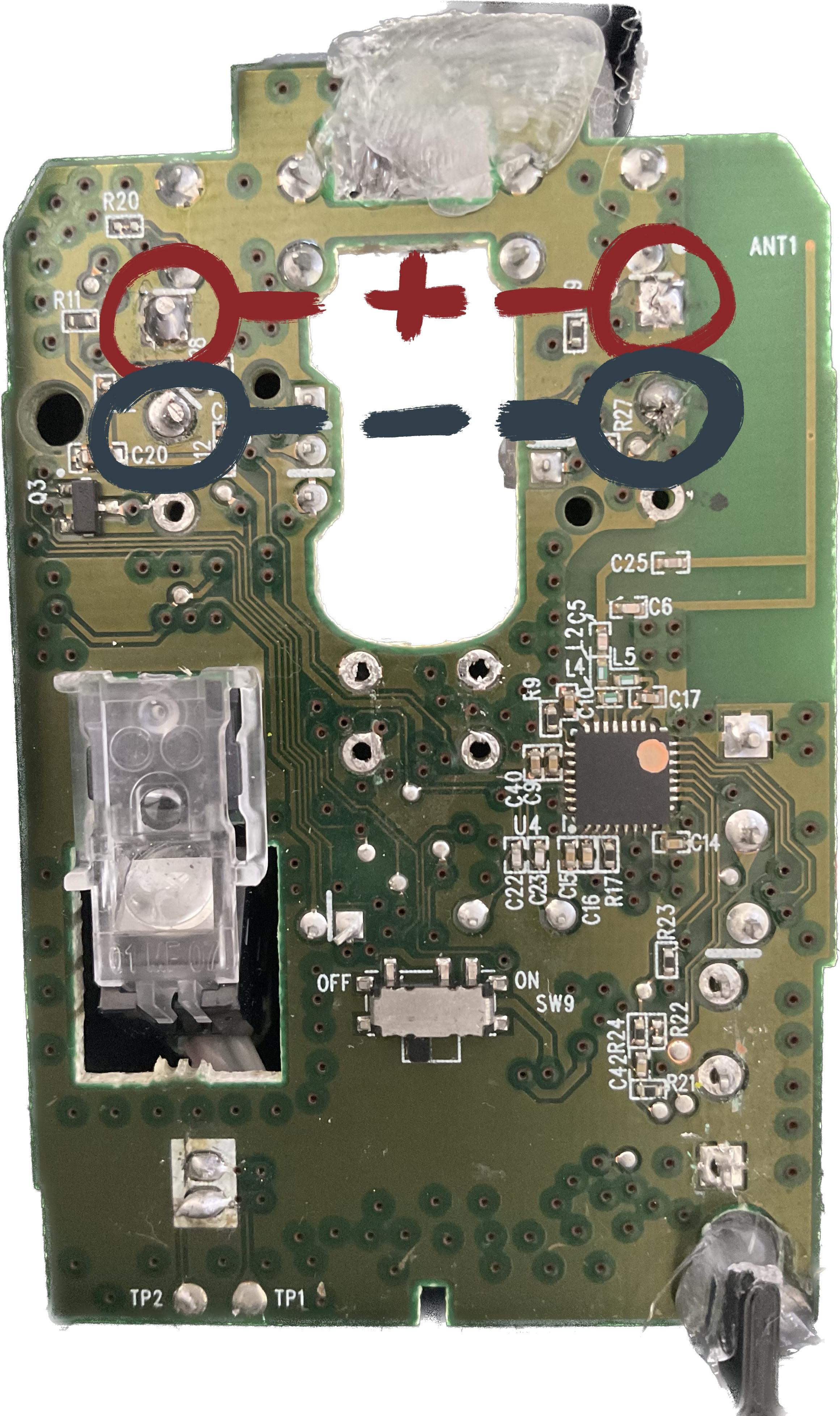
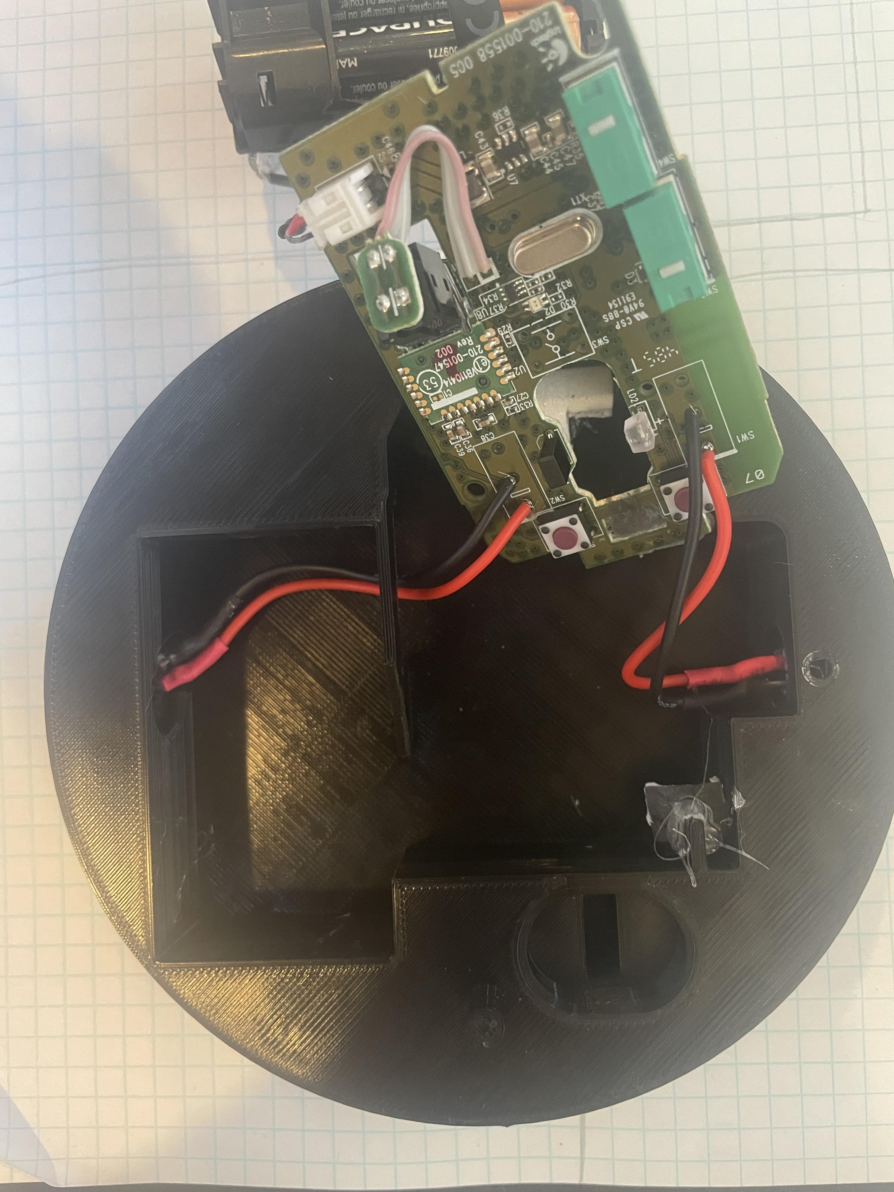
1. Route Battery Side Wires:
Carefully guide the battery side Mono Jack wires under the small 3D-Printed bridge.
2. Identify Solder Pads:
Identify the highlighted solder pads on their respective sides, as shown in the picture above, where the Mono Jack wires will be soldered. The bottom of the 3 pads will be left open.
3. Ensure Polarities:
Confirm that the positive wire, as defined earlier, is placed in the topmost of the three solder pads. Negative wire is placed in the middle pad.
4. Solder Wires:
Solder each Mono Jack wire to its designated solder pad on the appropriate side of the assembly.
5. Verify Connections:
After soldering, inspect and confirm that each wire is securely soldered to its designated solder pad.
Mouse Motherboard Mounting
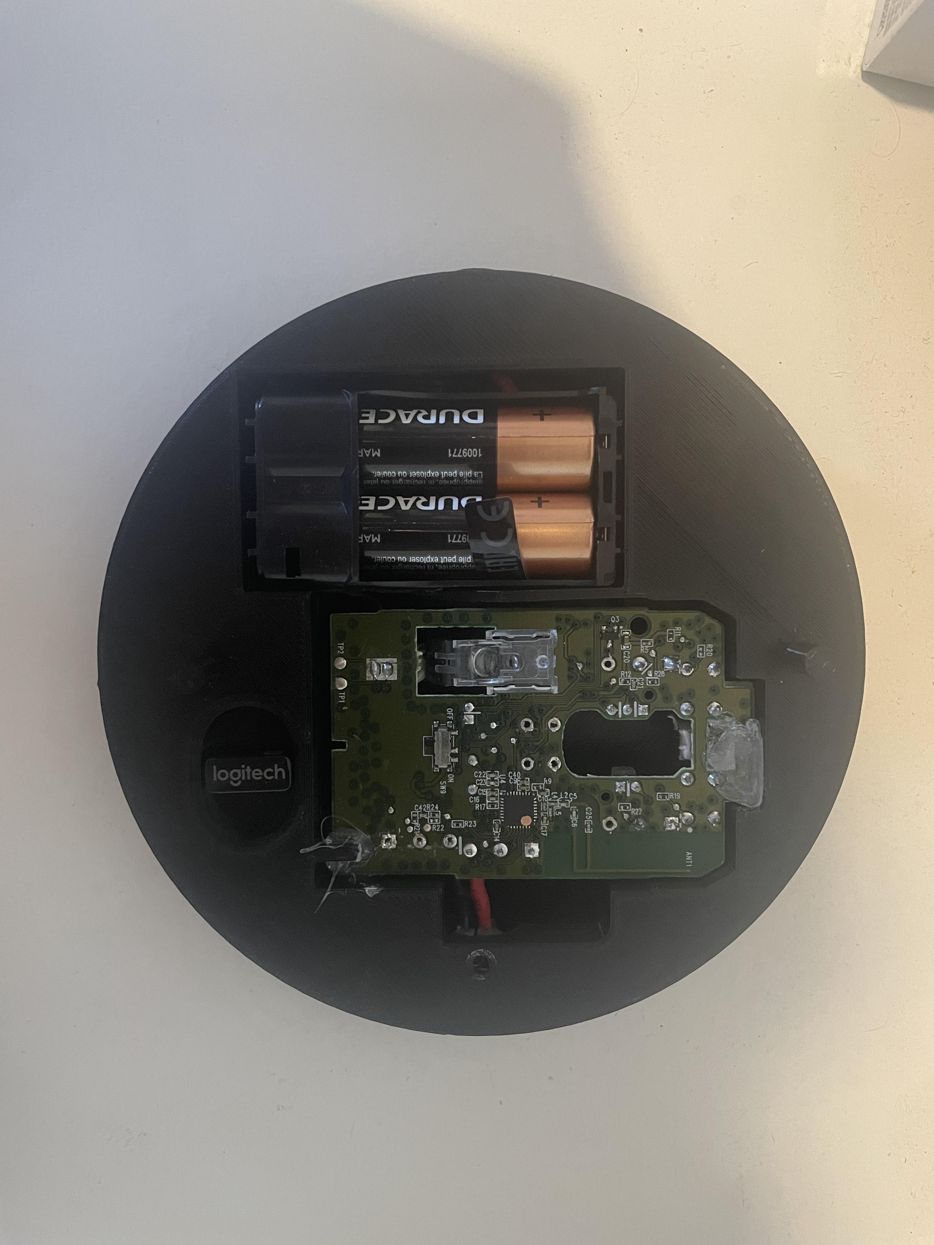
1. Mount Components:
Place the Mouse Motherboard and battery in their designated slots as shown in the provided image.
2. Optional Securement:
Optionally, enhance stability by using hot glue to secure the motherboard in place.
Mouse Assembly
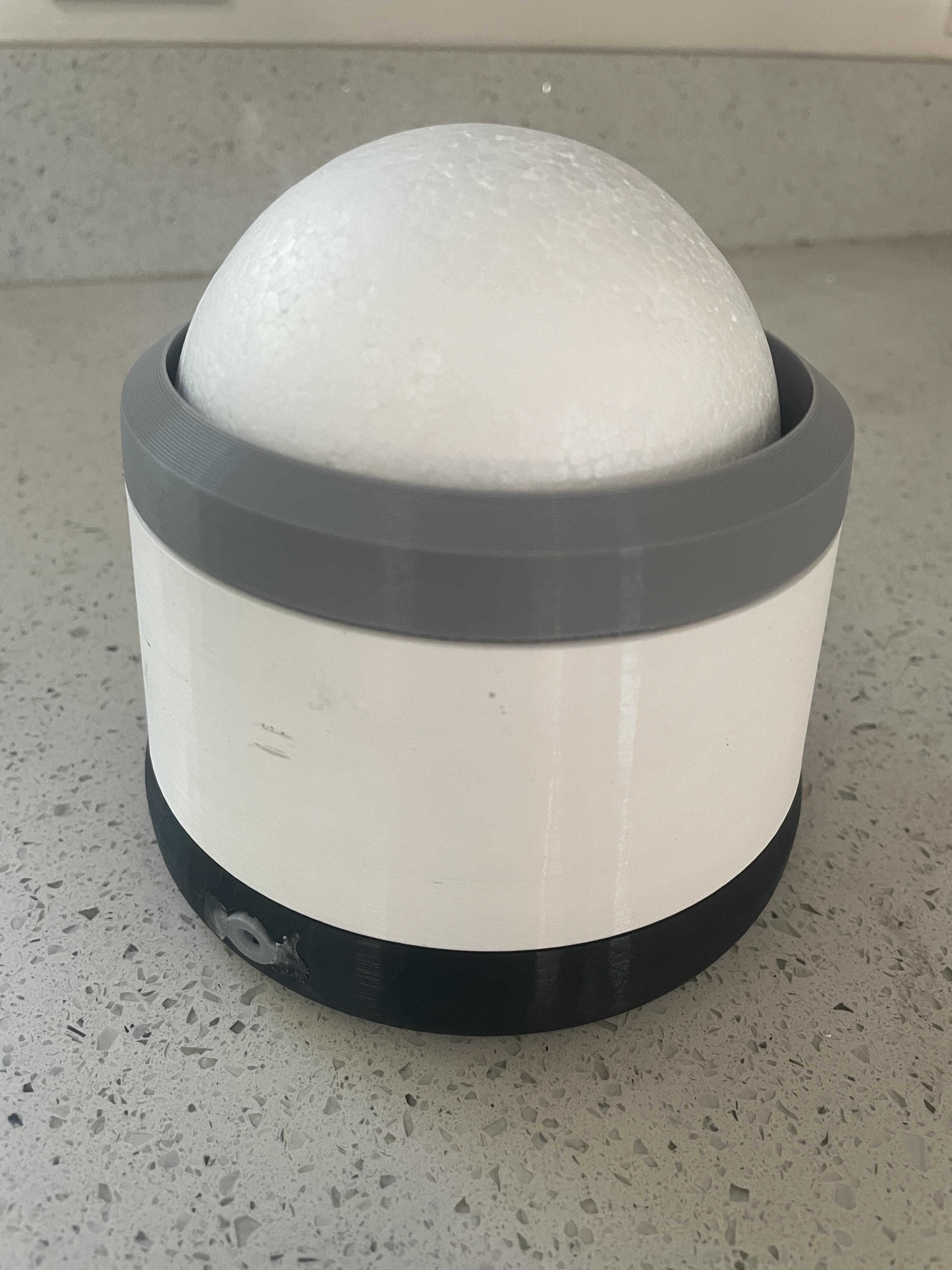
1. Assemble Foam Ball Assembly:
Place the foam ball in the top 3D-printed ball cradle. (White part in image above)
2. Secure Foam Ball:
Position the 3D-printed cover ring over the ball and push it into place. Optionally, secure with hot glue. (Grey part in image above)
3. Power On Mouse:
Turn on the mouse by switching the small switch on the mouse motherboard to the "on" position.
4. Attach Foam Ball:
Twist the foam ball assembly onto the bottom hub. (Black part in image above)
5. Test Mouse:
Verify functionality by plugging the USB dongle into a computer and testing the mouse.
Test Software
3D-Print Button Parts
No Supports:
3D-Print all parts using no supports!
Mono Jack (REPEAT)

Repeat Steps 4-7:
Only 2 paperclips are needed per Mono Jack and 1 Mono Jack is needed per button.
Button Paperclips
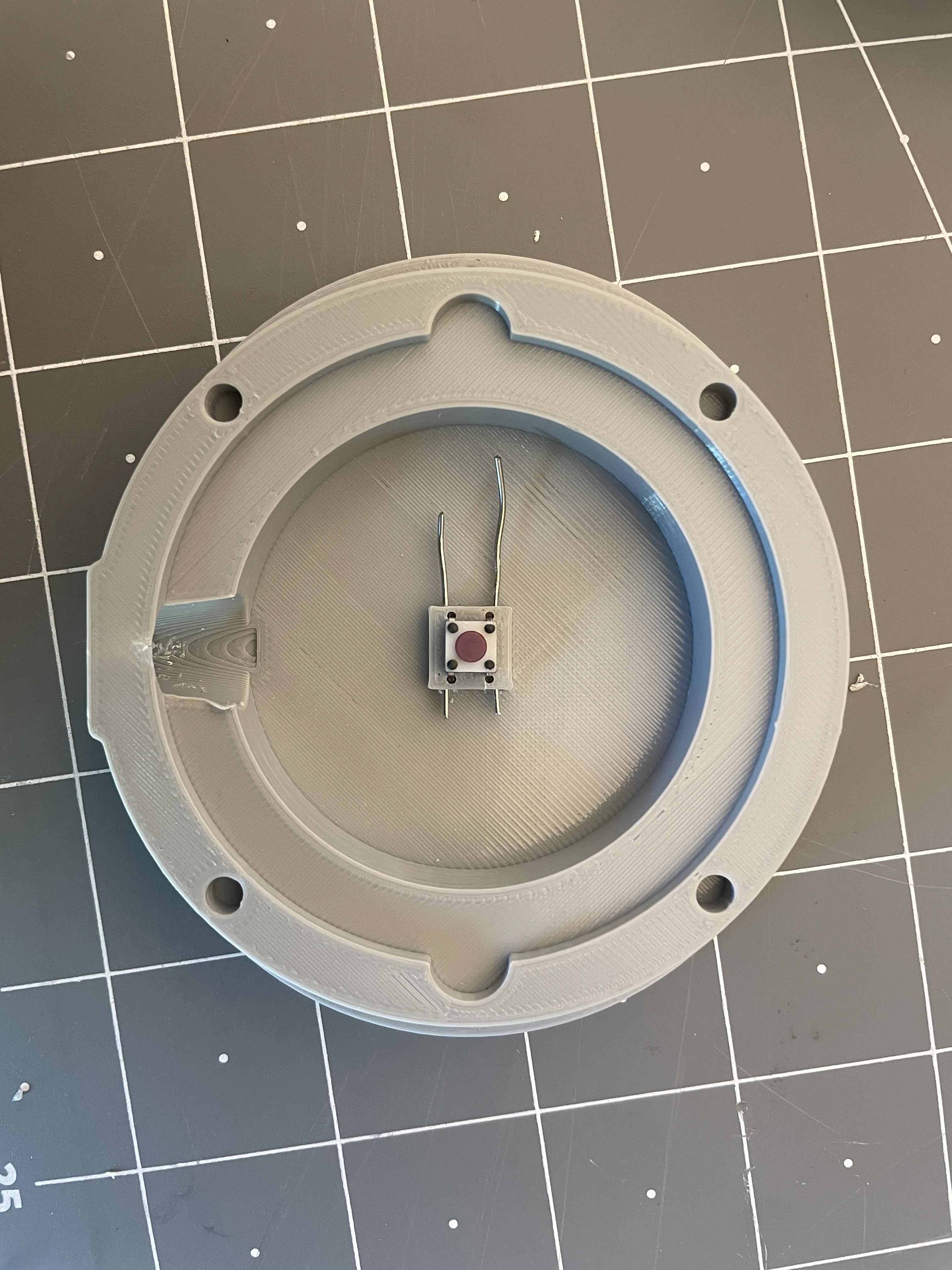
1. Prepare Paperclips:
Straighten and cut a paperclip in half.
2. Insert Paperclips:
Insert one half of a paperclip into each of the horizontal holes as shown in the image.
3. Use Desoldered Mouse Button:
Take the small square button desoldered from the mouse in Step 2 and push it into the four 3D-Printed Holes.
Button Soldering + Mouting
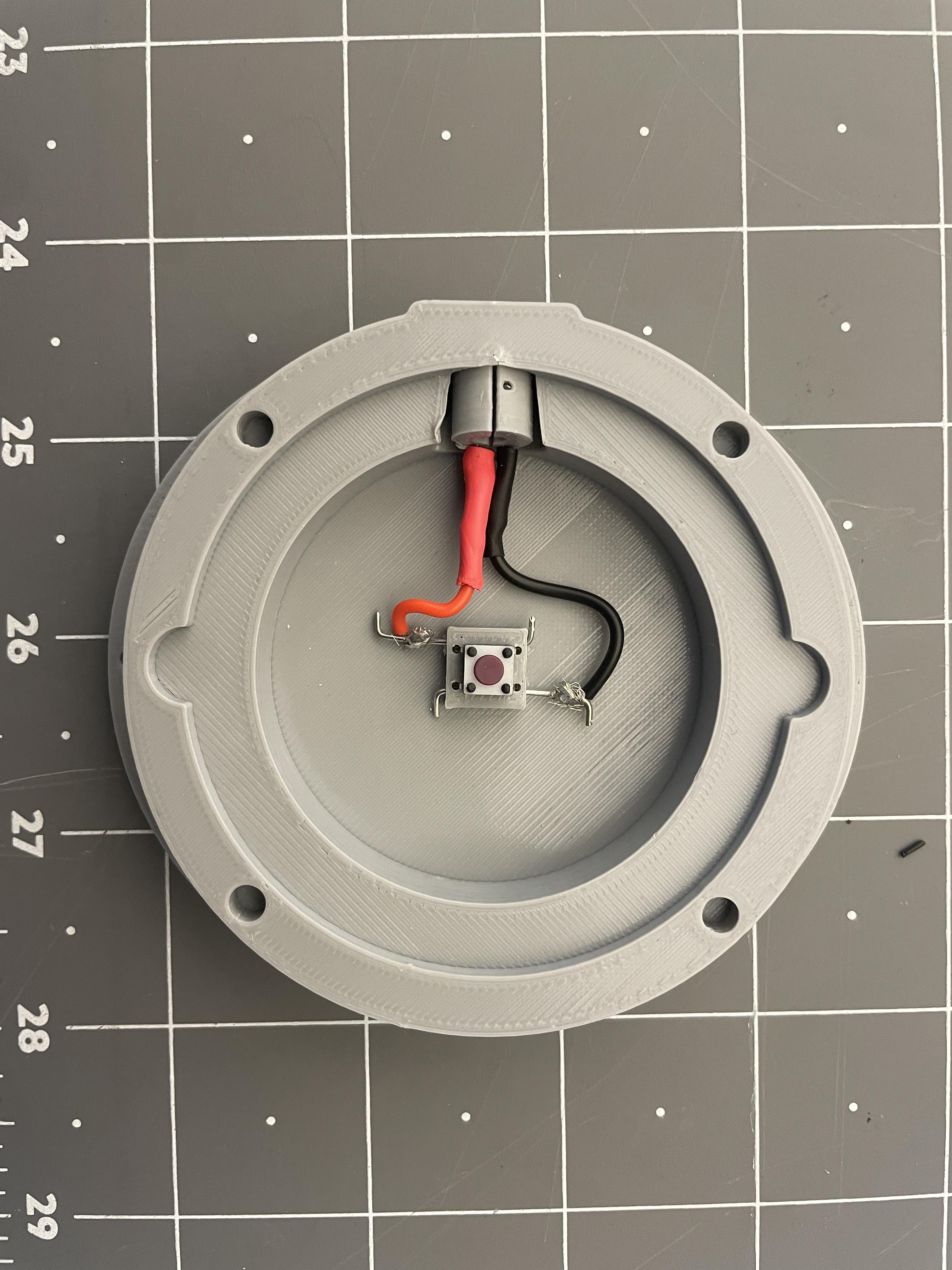
1. Mount Mono Jack:
Melt the Mono Jack with attached wires onto the assembly, similar to Step 7.
2. Adjust Wire Length:
Cut the wires to an appropriate length to fit inside the shell.
3. Solder to Paperclips:
Solder each wire to a protruding paperclip. Note: Polarity does not matter in this step.
4. Optional Securement:
Optionally, use hot glue to secure the wires in place and bend ends of paperclips to have small 90 degree bends.
Button Assembly
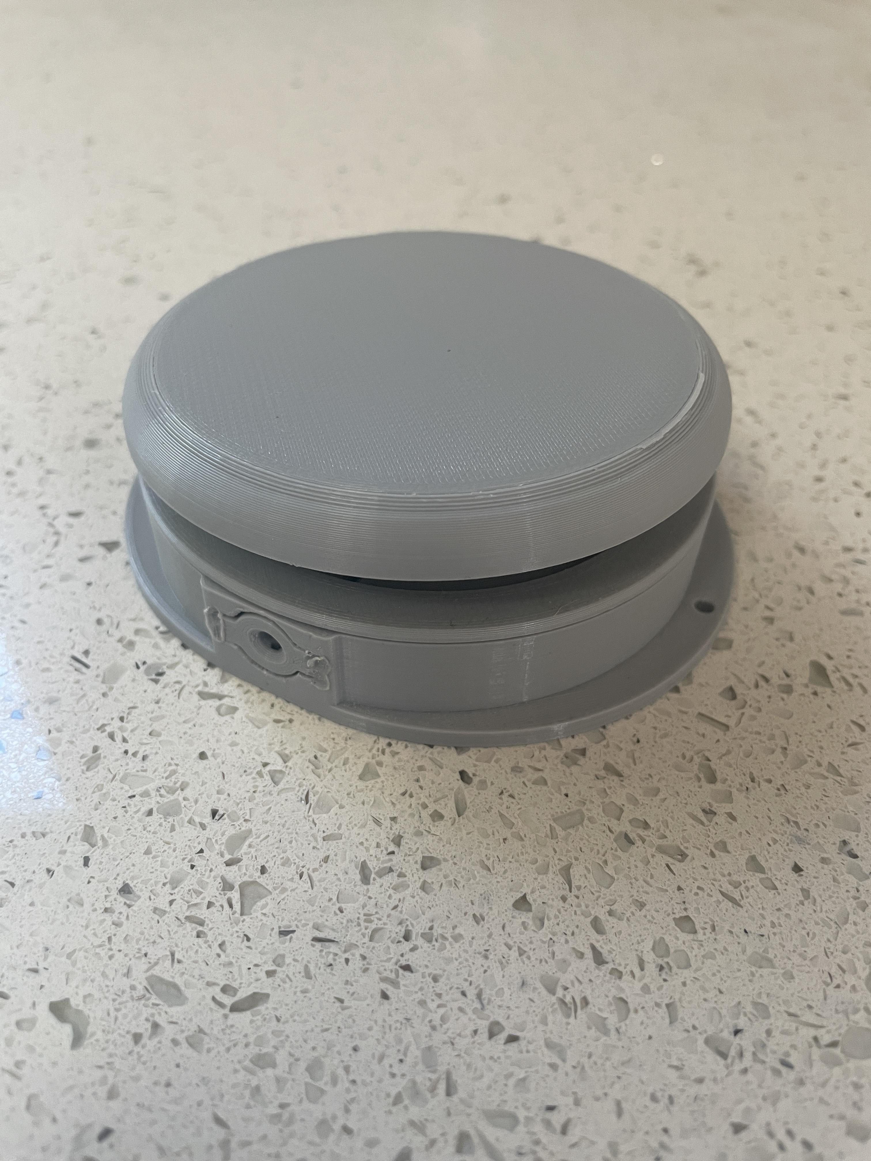
1. Insert Flat Spring:
Place the 3D-Printed flat spring into the slots of the button base, ensuring the side with the cutout is over the Mono Jack.
2. Attach Securing Ring:
Position the securing ring over the spring, aligning the pegs with the four holes on the base. Optionally, use hot glue for added security.
3. Attach Button Top:
Press the button top onto the spring. Optionally, use hot glue for added security.
Full Assembly

1. Connect Buttons:
Use a 3.5mm headphone cable to connect the mouse with up to two buttons. Ensure the mouse is switched on.
2. Start Using MouseMorphia:
Roll the foam ball to start using MouseMorphia!