Motor Driver Board Atmega328PU and HC01
by Arnov Sharma in Circuits > Robots
2506 Views, 10 Favorites, 0 Comments
Motor Driver Board Atmega328PU and HC01

.gif)
.gif)
.gif)

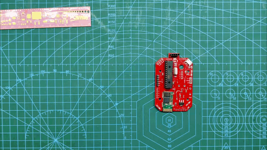
Hey, what's up folks here's something super cool and useful if you're making a basic Robot Setup, A MOTOR DRIVER CONTROLLER BOARD that controls the motor driver by an Onboard MCU and has an HC01 BT Module for Bluetooth connectivity.
I added four mounting Holes on the PCB so I could add PCB Standoffs to hold the motor driver on the top side of the board in the air. It's a clever method to use standoffs as we can add multiple Modules with this method just by stacking them up in a row of standoffs.
I've also added an HC-SR04 Ultrasonic Sensor Breakout Pin on one side of the board so it can be used to make an obstruction-avoiding robot.
This Instructables is gonna be about the build process of this motor driver, so let's get started.
Supplies
Following were the things I used in this Project-
- Custom PCB
- Atmega328PU
- 22PF Cap 0603 Package
- 16Mhz Crystal
- 10K Resistor 0603 Package
- 1K Resistor 0603 Package
- Indicator LED 0603 Package
- AMS1117 Voltage Regulator
- HC01 BT Module
- 10uF Cap 1206 Package
- 1uF Cap 1206 Package
- IC Socket DIP 28
- USB Micro Port
- Header Pin socket
- Arduino as ISP Setup for flashing Atmega328PU
- PCB Standoffs
- Motor
- Ultrasonic Sensor HC-SR04
- Battery Pack 12V
- Motor Driver L298N
Schematic
.jpg)
Here's the schematic that I prepared, it consists of a minimal Atmega328PU setup that is connected with an HC01 module. between Atmega328PU and HC01, there's an AMS1117 3.3V Voltage regulator for stepping down 5V from VCC to 3.3V for HC01 to work.
I've added a bunch of connectors for connecting stuff with atmega that includes ISP out which breakout SPI pins of Atmega for flashing, then I also added CON4 for motor driver IN1, IN2, IN3, and IN4 with D6, D9, D10, and D11.
I also added a few LEDs with D2, D3, and D4 along with a CON4 header pin for connecting the Ultrasonic sensor with this board.
After finalizing the schematic, I converted it into a board file.
PCB Design

.gif)

As for the design, I made a rectangular board with a chamfer at the edges, also I placed four mounting holes at the center of the board so I could place the L298N Motor driver on this PCB by using Standoffs.
PCBWAY
.gif)
.gif)
.gif)
After completing the design, I uploaded the Gerber data on PCBWAY's quote page, selected the solder mask color which was RED, and placed the order.
After placing the order, I received the PCBs in a week and the PCB quality was pretty great.
This shape is completely random so it's pretty hard to make but they did an awesome job of making this PCB with no error whatsoever.
Do check them out for getting great PCB Sevice for a less price.
PCB ASSEMBLY
the PCB Assembly Process will have the following steps.
- Solder Paste Dispensing
- Pick & Place Process
- Hotplate Reflow
- Adding Remaining THT Components
- Burning Bootloader
SOLDER PASTE
.gif)
The first step is to apply solder paste to each component pad.
I used a normal Sn-Pb solder paste which has a melting temp from 140 to 270 °C.
After Adding solder paste, we move on to the next process which is the "PICK & Place Process"
PICK & PLACE
.gif)
I then used an ESD Tweeaser to carefully pick and place each SMD component in their assigned place one by one which took like 30 Seconds tops but the result was a perfect PCB with all the components placed in their location.
HOTPLATE REFLOW
.gif)
.gif)
After the "PICK & Place Process", I carefully lifted the whole circuit board and place it on my DIY SMT Hotplate which is also homemade just like this project.
After a Few mins when the hotplate reaches the Solderpaste melting TEMP, all the components will get soldered by this Hot Reflow process.
We then remove the PCB from the Hotplate to cool down all componenets and board surface.
Testing the Board
.gif)
I then Plugged in a 5V Supply through USB Port to check if the HC01 was working or not, the LED on one side of the HC01 will blink if the setup is working properly.
THT Componenets
.gif)
In the end, we add THT Components to the PCB which are Atmega Socket and header pins.
After doing this, Our Circuit is completed!
Atmega328PU Burning Bootloader Via Arduino As ISP
.gif)
.gif)
Now, this setup uses an Atmega328PU. Atmega328PU has a little hex file onboard known as a bootloader which is similar to BIOS. cheap atmega328PU don't usually come with a preinstalled bootloader so I have to burn the bootloader onto the MCU and for that, I used one of my previous projects which was an Arduino Based Attiny Programmer.
This Programmer was made for Burning the bootloader and Flash code into the AVR and Attiny MCUs by using "Arduino as ISP Sketch" uploaded into a regular Arduino Nano R3 with few tweaks (adding 1uf Cap between reset and GND)
see my previous project for making this programmer and getting started with this flashing method.
I connected the SPI Pins of Atmega328PU through a header pin socket with SPI Pins of Arduino Nano together and Burn the bootloader of Atmega328PU, and uploaded ULTRASONIC SENSO TEST SKETCH for testing the Atmega chip.
Test Sketch #1 Ultrasonic Sensor
.gif)
#define trigPin 7
#define echoPin 8
#define led 2
#define led2 3
#define led3 4


void setup() {
  Serial.begin (9600);
  pinMode(trigPin, OUTPUT);
  pinMode(echoPin, INPUT);
  pinMode(led, OUTPUT);
  pinMode(led2, OUTPUT);
  pinMode(led3, OUTPUT);


}

void loop() {
  long duration, distance;
  digitalWrite(trigPin, LOW);
  delayMicroseconds(2);
  digitalWrite(trigPin, HIGH);
  delayMicroseconds(10);
  digitalWrite(trigPin, LOW);
  duration = pulseIn(echoPin, HIGH);
  distance = (duration/2) / 29.1;


  if (distance <= 30) {
    digitalWrite(led, HIGH);

}
  else {
    digitalWrite(led,LOW);
  }
  if (distance < 20) {
      digitalWrite(led2, HIGH);

}
  else {
      digitalWrite(led2, LOW);
  }

    if (distance < 10) {
      digitalWrite(led3, HIGH);

}
  else {
      digitalWrite(led3, LOW);
  }

  delay(500);
}
I added the HC-SR04 Ultrasonic Sensor module in its assigned Header Pin socket and uploaded the test sketch I made. When we put anything in front of it at a 30cm distance, the first led glows, by decreasing the distance the other two LEDs glow.
Test Sketch #2 BT Terminal LED ON/OFF
.gif)
char junk;
String inputString="";

void setup()                    // run once, when the sketch starts
{
 Serial.begin(9600);            // set the baud rate to 9600, same should be of your Serial Monitor
 pinMode(2, OUTPUT);
}

void loop()
{
  if(Serial.available()){
  while(Serial.available())
    {
      char inChar = (char)Serial.read(); //read the input
      inputString += inChar;        //make a string of the characters coming on serial
    }
    Serial.println(inputString);
    while (Serial.available() > 0)
    {
      junk = Serial.read() ; }      // clear the serial buffer
    }
    if(inputString == "on"){         //in case of 'a' turn the LED on
      digitalWrite(2, HIGH);
    }
    else if(inputString == "off"){   //incase of 'b' turn the LED off
      digitalWrite(2, LOW);
    }
    inputString = "";
    }
After checking the Ultrasonic Sensor, I uploaded the BT Test Sketch into the MCU and used a BT Terminal APP to connect with HC01.
By Sending "on" with BT Terminal APP to HC01, the LED turns ON, and sending "off" will turn it OFF.
Adding Motor Driver With PCB Standoff
.gif)
.gif)
.gif)
After testing the board that it was working properly, I then move on to the next step which was to add the L298N Motor driver to the mainboard by using PCB Standoffs.
Adding Wires Connector Between Mainboard and Motor Driver
.gif)
.gif)
.gif)
I then added wires between the Motor controller's VCC GND and 5V and Motor Driver's VCC GND and 5V.
I then added wires between the Motor controller's Control Pins and Pwm pins of Atmega328pu.
- ENA and ENB are both High
- IN1 to D6
- IN2 to D9
- IN3 to D10
- IN4 to D11
And the setup is completed, now we can add the Battery to the Motor driver's VCC and GND port and add the motor's terminals to the Motor driver's connector.
Adding Motor and Battery
.gif)
.gif)
Final Sketch -Testing the Motor
.gif)
.gif)
.gif)
int motorLpin1 = 6;
int motorLpin2 = 9;
int motorRpin1 = 10;
int motorRpin2 = 11;
int LED1 = 2;
int LED2 = 3;
int LED3 = 4;

void setup()
{
  Serial.begin(9600);
  Serial.flush();
  pinMode(motorLpin1,OUTPUT);
  pinMode(motorLpin2,OUTPUT);
  pinMode(motorRpin1,OUTPUT);
  pinMode(motorRpin2,OUTPUT);
  pinMode(LED1,OUTPUT);
  pinMode(LED2,OUTPUT);
  pinMode(LED3,OUTPUT);


}

void loop(){
  String input="";
  while(Serial.available()){
    input+=(char)Serial.read();
    delay(5);
  }

  if(input=="S"){
    MotorStop();
  }
  else if(input=="F"){
    MotorForward();
  }
  else if(input=="R"){
    MotorBackward();
  }
  else if(input=="TL"){
    MotorLeft();
  }
  else if(input=="TR"){
    MotorRight();
  }

 }

void MotorForward(void)
{
  digitalWrite(motorLpin1,HIGH);
  digitalWrite(motorLpin2,LOW);
  digitalWrite(motorRpin1,HIGH);
  digitalWrite(motorRpin2,LOW);
  digitalWrite(LED1,HIGH);
  digitalWrite(LED2,LOW);
  digitalWrite(LED3,LOW);
}

void MotorBackward(void)
{

  digitalWrite(motorLpin1,LOW);
  digitalWrite(motorLpin2,HIGH);
  digitalWrite(motorRpin1,LOW);
  digitalWrite(motorRpin2,HIGH);
  digitalWrite(LED1,LOW);
  digitalWrite(LED2,HIGH);
  digitalWrite(LED3,LOW);
}
void MotorLeft(void)
{
  digitalWrite(motorLpin1,HIGH);
  digitalWrite(motorLpin2,LOW);
  digitalWrite(motorRpin1,LOW);
  digitalWrite(motorRpin2,HIGH);
  digitalWrite(LED1,LOW);
  digitalWrite(LED2,LOW);
  digitalWrite(LED3,HIGH);
}
void MotorRight(void)
{

  digitalWrite(motorLpin1,LOW);
  digitalWrite(motorLpin2,HIGH);
  digitalWrite(motorRpin1,HIGH);
  digitalWrite(motorRpin2,LOW);
  digitalWrite(LED1,LOW);
  digitalWrite(LED2,LOW);
  digitalWrite(LED3,HIGH);

}
void MotorStop(void)
{

  digitalWrite(motorLpin1,LOW);
  digitalWrite(motorLpin2,LOW);
  digitalWrite(motorRpin1,LOW);
  digitalWrite(motorRpin2,LOW);
  digitalWrite(LED1,LOW);
  digitalWrite(LED2,LOW);
  digitalWrite(LED3,LOW);

}
I uploaded the above sketch into the Atmega and then added a Gear DC Motor with a Motor driver's Connector and added a 12V Battery pack to power this whole system.
For controlling the motor, I'm using a BT Terminal app that connects with the HC01 Module to send the MCU "F" for forward and "B" for backward.
for stopping the motor, we send "S" through the BT Terminal and the motor stops rotating.
What's Next, Make a Robot
.gif)
.gif)
The next step or next use of this Motor Controller will be to construct a robot, I'm currently designing a robot that will use this Controller setup so stay tuned for that.
If you're into robots then check out my previous robot project-
Thanks, PCBWAY for supporting this project, do check them out if you need great PCB Service for less cost, and I'll be back with a new project soon.
Peace