Motion Controlled RGB Led Suit Using Xbox 360 Kinect, Max MSP and Arduino Part 1
by kyofanatic1 in Circuits > LEDs
4426 Views, 22 Favorites, 0 Comments
Motion Controlled RGB Led Suit Using Xbox 360 Kinect, Max MSP and Arduino Part 1
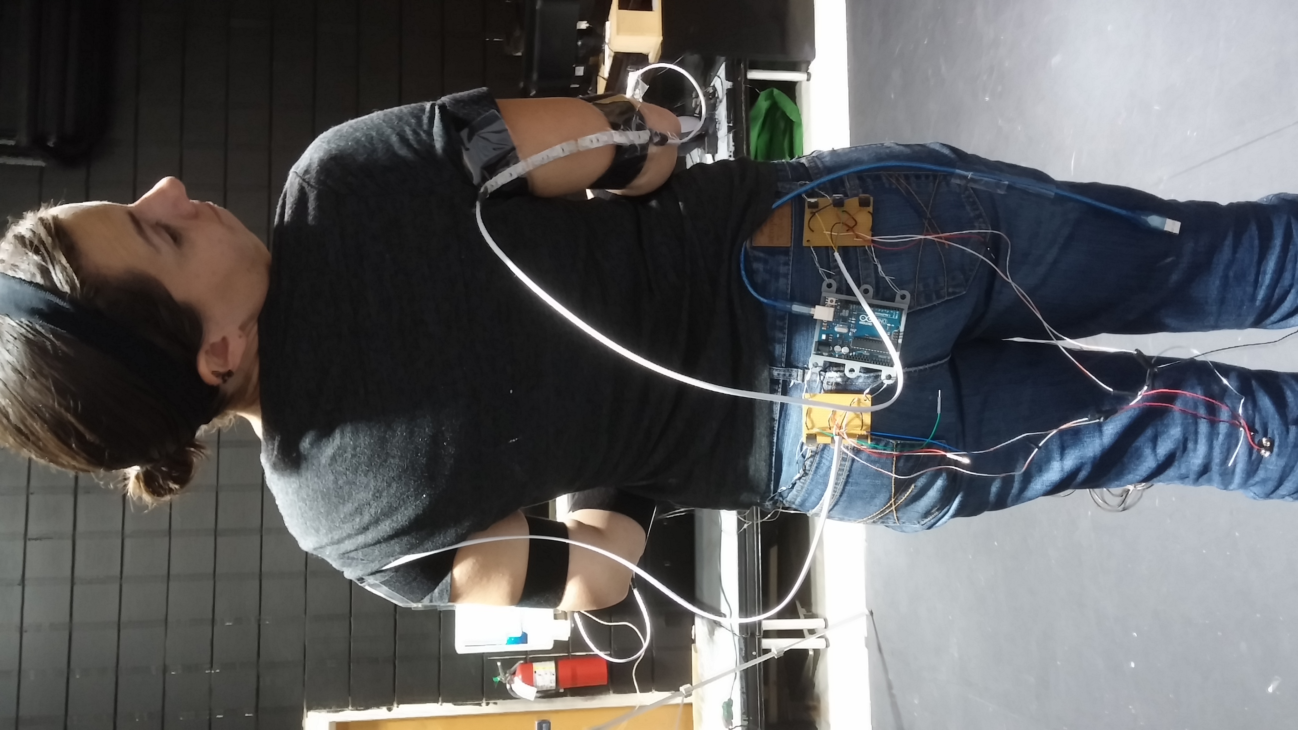
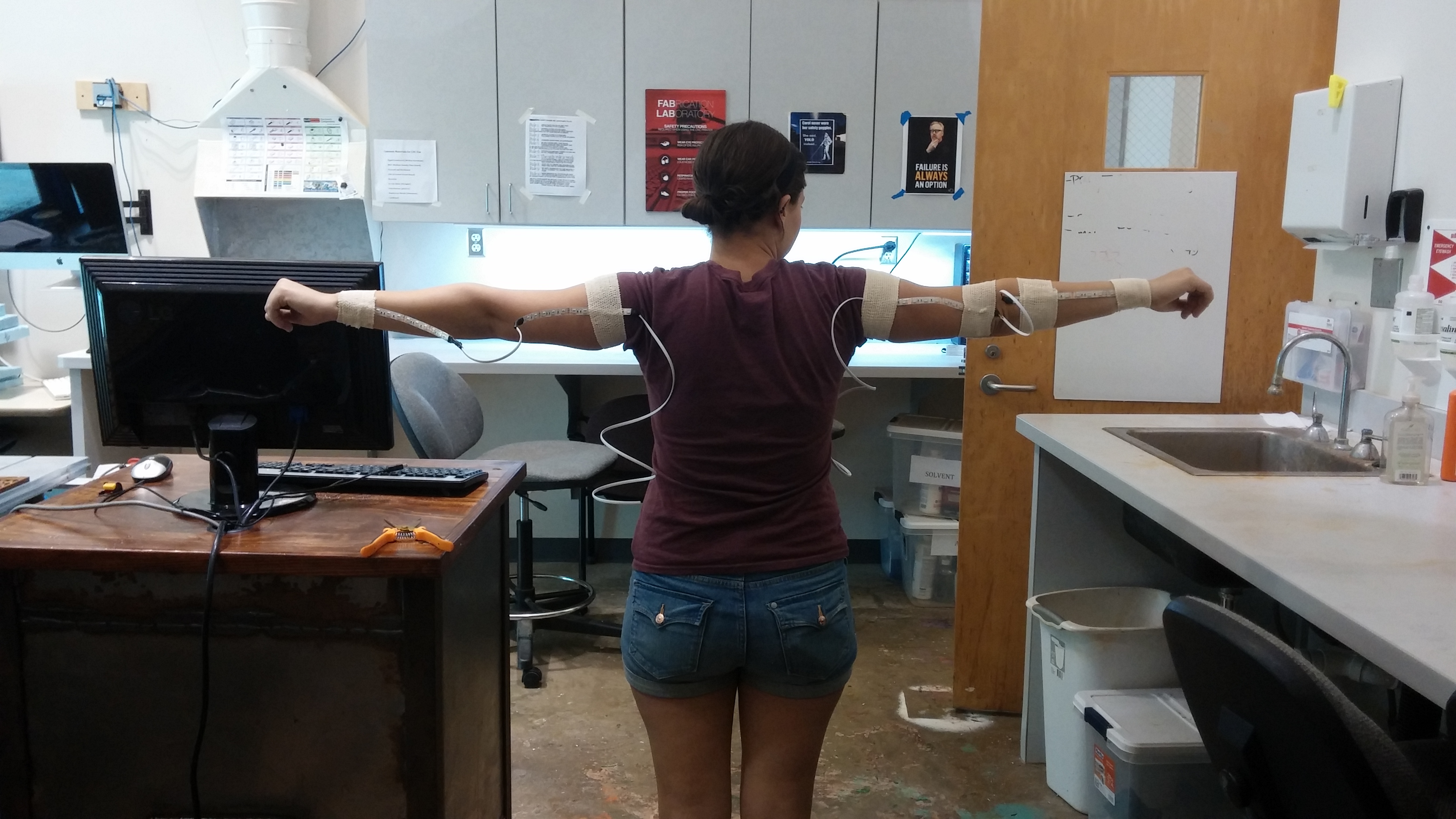
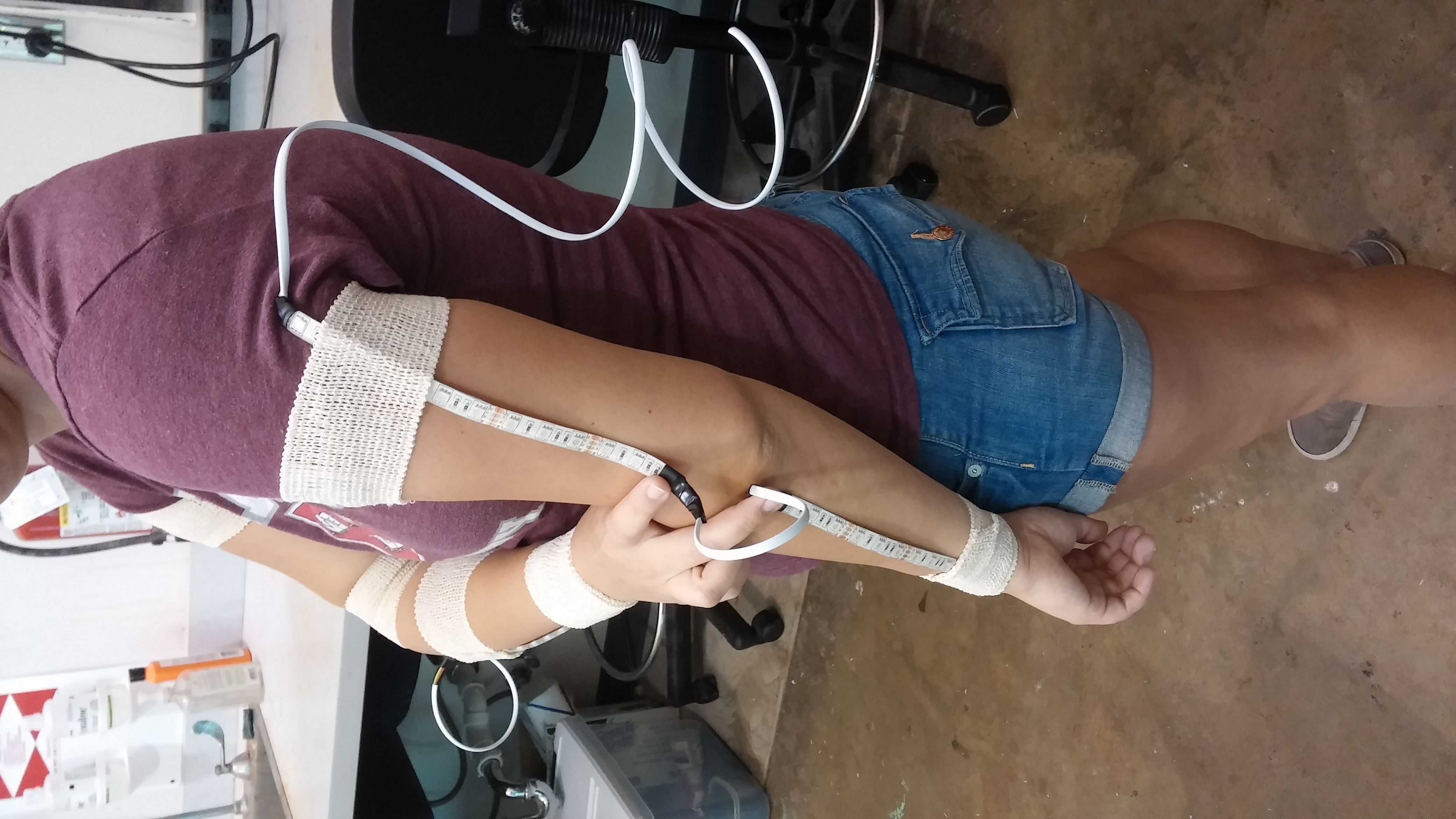
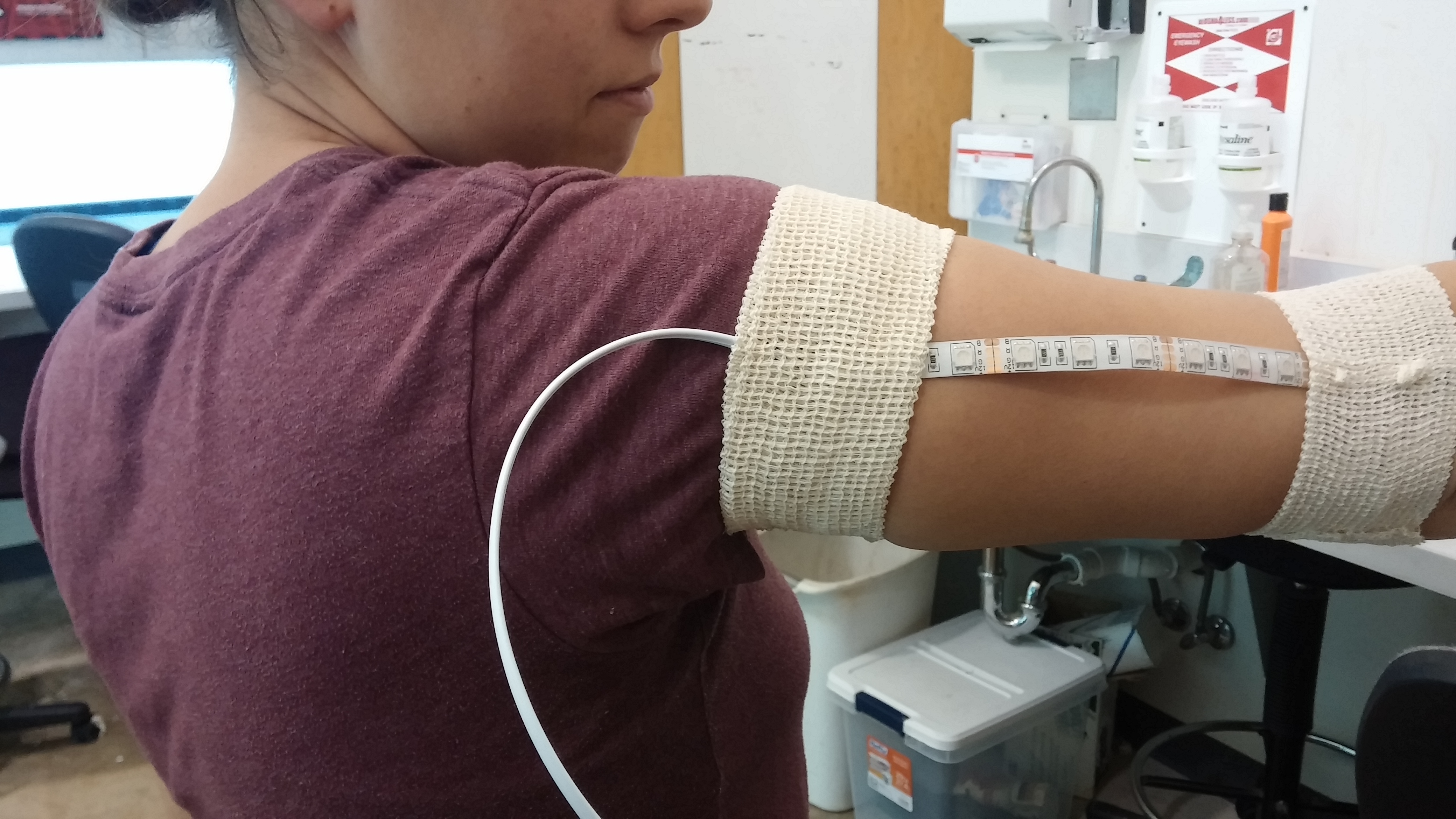
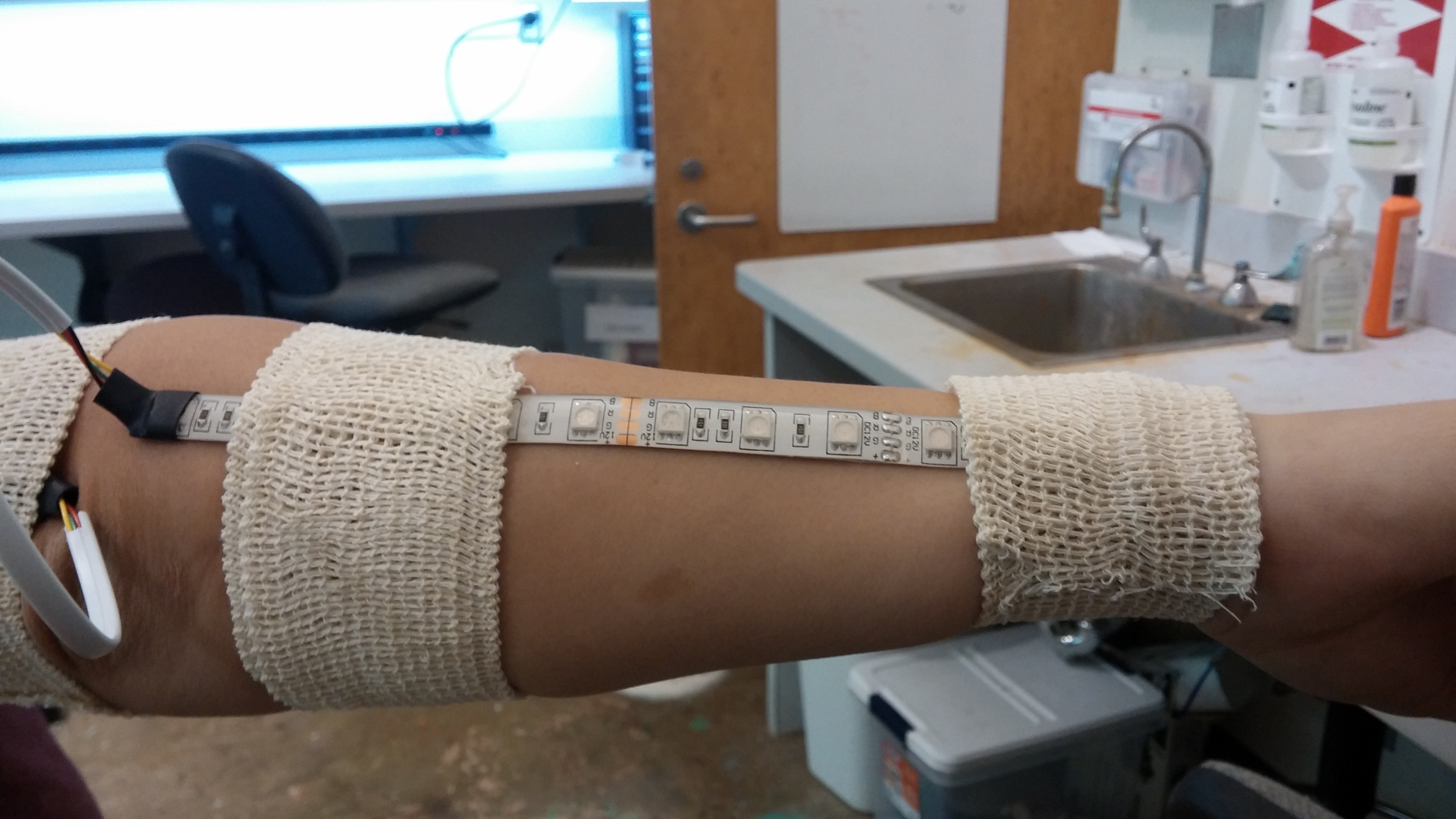
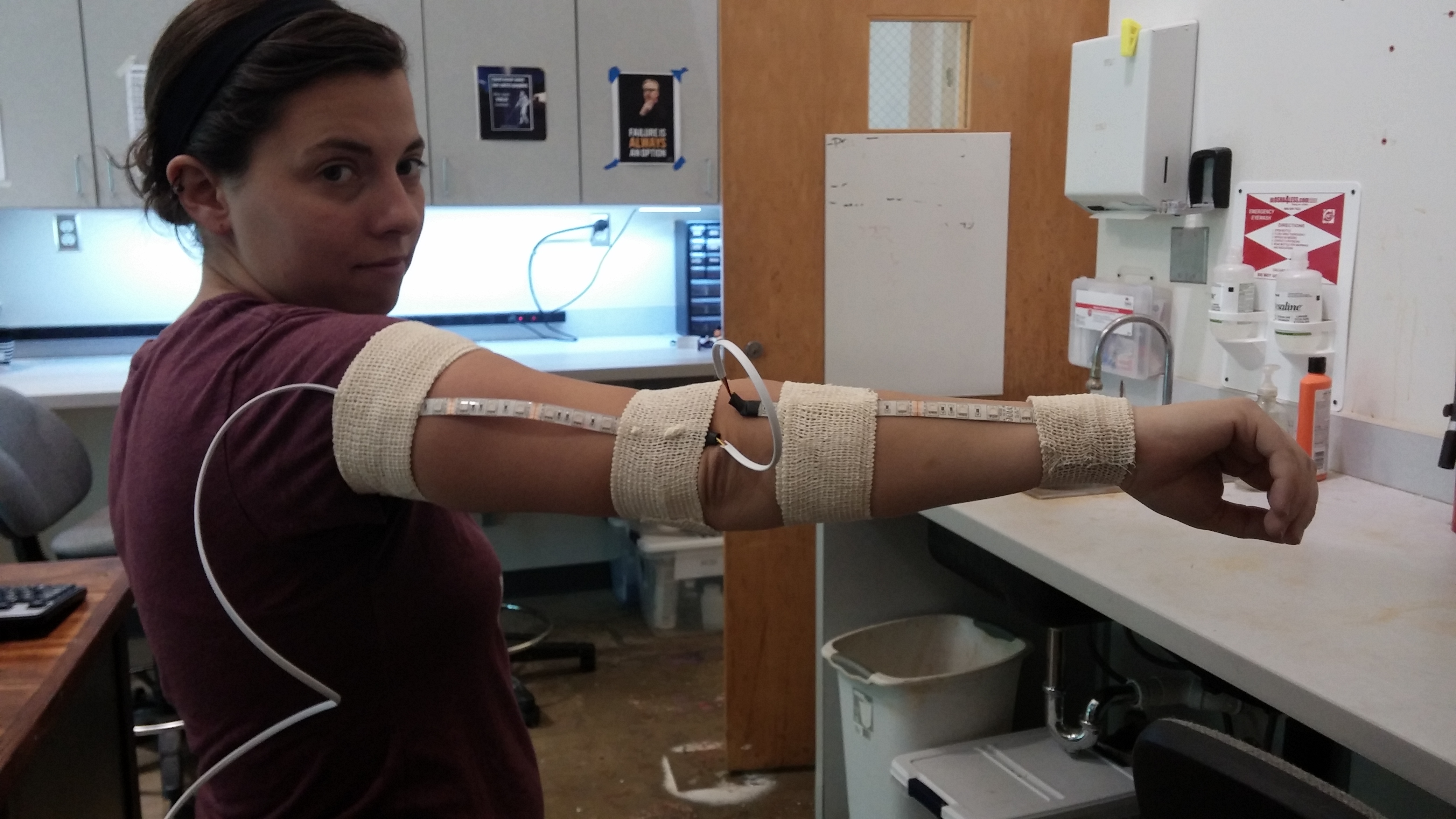
For the past few months I have been working on a kinect project I wanted to created an led outfit that responded to the movements of the wearer. So far I only have the arms done, and there are some problems that need to be worked out, but it works great so far.
What You Need
- Arduino Uno
- 2 9 volt Batteries
- 30ft powered usb cable
- Xbox 360 Kinect
- Max MSP Found here
- .22 gauge stranded wire. I suggest at least 4 colors, or an ethernet cable. I used and ethernet cable.
- Velcro
-Hot Glue
-Rgb Led strip You can get 5 meters for $20 on amazon
-MOSFET N-Ch 60 Volt 16 Amp Can be found here
- 2 prototype boards
- Electrical tape
-Synapse Found here
-Kinect-via-synapse Found here
Step 1 Wiring Your LEDS
1.Get you RGB Leds and your wire. Cut the leds to the length of your arm from shoulder to elbow, then from elbow to wrist. Make sure you cut them on the black line between the copper pads, other wise you will break your leds.
2. If you got the water proof kind you need to take the water proof coating off just over the copper pads.
3. Take your wires, and solder them to the copper pads, and use the wire to connect the upper and lower arm leds. Make sure there is enough wire so that the person can move. Then solder more wire to the upper arm portion making sure there is enough wire to connect it to the boards
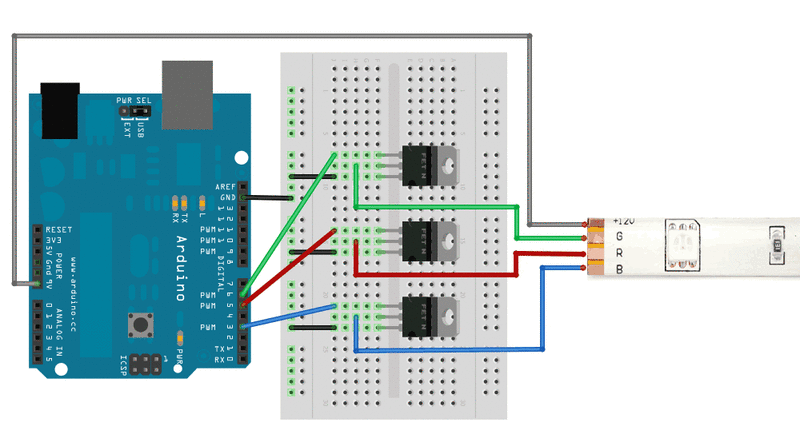
Next you need to hook your leds up to the board. Use the diagram provided to connect your leds. Use the code below to test them to make sure you soldered them right.
#define REDPIN 5
#define GREENPIN 6
#define BLUEPIN 3
#define FADESPEED 5 // make this higher to slow down
void setup() {
pinMode(REDPIN, OUTPUT);
pinMode(GREENPIN, OUTPUT);
pinMode(BLUEPIN, OUTPUT);
}
void loop() {
int r, g, b;
// fade from blue to violet
for (r = 0; r < 256; r++) {
analogWrite(REDPIN, r);
delay(FADESPEED);
}
// fade from violet to red
for (b = 255; b > 0; b--) {
analogWrite(BLUEPIN, b);
delay(FADESPEED);
}
// fade from red to yellow
for (g = 0; g < 256; g++) {
analogWrite(GREENPIN, g);
delay(FADESPEED);
}
// fade from yellow to green
for (r = 255; r > 0; r--) {
analogWrite(REDPIN, r);
delay(FADESPEED);
}
// fade from green to teal
for (b = 0; b < 256; b++) {
analogWrite(BLUEPIN, b);
delay(FADESPEED);
}
// fade from teal to blue
for (g = 255; g > 0; g--) {
analogWrite(GREENPIN, g);
delay(FADESPEED);
}
}
Once you know everything works, wrap electrical tape around where you soldered the leds, and solder all the parts to a prototype board.
Once you have done all that attach the velcro to to the underside of the leds using the hot glue, so that you can put the leds on a person.
Step 2 Kinect, Synapse, and Max MSP
1. Plug your kinect into your computer and open Synapse. You might have to try at a few times to get them to connect, but the kinect has to be plugged in to the computer and plugged into the wall in order for Synapse to open. If Synapse doesn't open you need to find an older kinect.
2. Once you have Synapse open, open Kinect-via-synapse in Max MSP. Click the dots over the right and left hand, so that those two points are being tracked.
3. Next download and open the file below It is Called dimmer8.maxpat
Max file
2. Once you have Synapse open, open Kinect-via-synapse in Max MSP. Click the dots over the right and left hand, so that those two points are being tracked.
3. Next download and open the file below It is Called dimmer8.maxpat
Max file
Aurduino
Just download the code below, and upload it to your arduino.
const int LEDone = 9;
const int LEDtwo = 11;
const int LEDthree = 10;
const int LEDfour = 5;
const int LEDfive = 6;
const int LEDsix = 3;
int currentPin = 0;
int brightness = 0;
void setup(){
Serial.begin(9600);
pinMode(LEDone, OUTPUT);
pinMode(LEDtwo, OUTPUT);
pinMode(LEDthree, OUTPUT);
pinMode(LEDfour, OUTPUT);
pinMode(LEDfive, OUTPUT);
pinMode(LEDsix, OUTPUT);
}
void loop(){
if(Serial.available()>0){
int inByte = Serial.read();
Serial.write(inByte);
if(inByte =='a'){
currentPin = LEDone;
}
if(inByte == 'b')
{ currentPin = LEDtwo; }
if(inByte == 'c')
{ currentPin = LEDthree; }
if(inByte =='d'){
currentPin = LEDfour;
}
if(inByte == 'e')
{ currentPin = LEDfive; }
if(inByte == 'f')
{ currentPin = LEDsix; }
if (inByte>=0 && inByte<=255){
brightness = inByte;
analogWrite(currentPin, brightness);
}
}
}
You will probably have to alter the port information in MAX on the file I gave you to get the arduino to talk to MAX. Other wise you should be good to go.