Motion-Triggered Music Player
by jenfoxbot in Circuits > Raspberry Pi
37489 Views, 81 Favorites, 0 Comments
Motion-Triggered Music Player
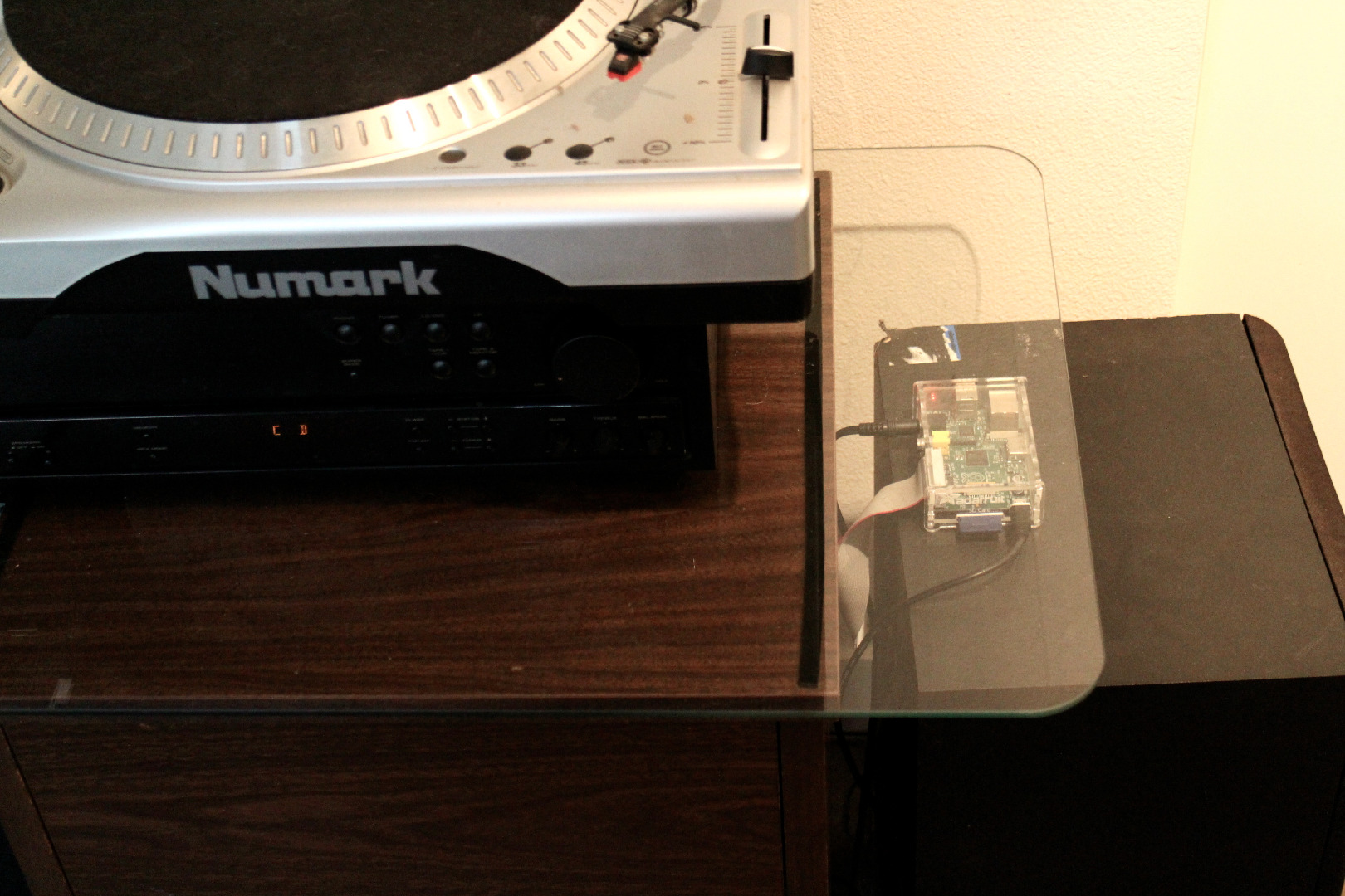
Turn on music as soon as you walk into a room! This tutorial covers a minimalistic entrance sensor that triggers music of your choice. The design can easily be adapted to suit a variety of needs (e.g. alarm system, motion-triggered lights, etc.).
The system is controlled by a Raspberry Pi, and aside from the RPi and speakers, the materials cost is extremely low (~ $20). Build time is approximately 1 - 2 hours.
For an inexpensive set of speakers, check thrift stores and/or friends' garages.
Materials
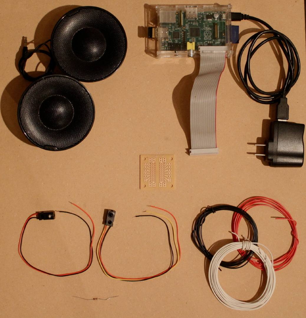
1. Raspberry Pi + Accessories
This tutorial assumes that the RPi has been set up and includes all necessary accessories (e.g. power cord, SD card, etc.). It is also recommended to use an RPi that has been set up for wireless and with a GPIO breakout cable.
Here's a tutorial on how to set up the RPi.
2. Infrared (IR) Breakbeam Sensor(s)
3. 10 kOhm Resistor
4. Speakers w/ 1/8" audio jack (standard headphone jack)
5. 22 or 24 gauge wire (min. 15 feet)
Recommended to get at least two to three colors (e.g. red, black & yellow).
6. Optional: PCB board and/or Connectors
Although not necessary, a small PCB is recommended to make the system more robust and longer lasting.
Add connectors between the sensor and RPi GPIO for simpler installation, transportation and to more easily allow for future customization.
7. Recommended: LED + 10kOhm Resistor (for testing)
Tools
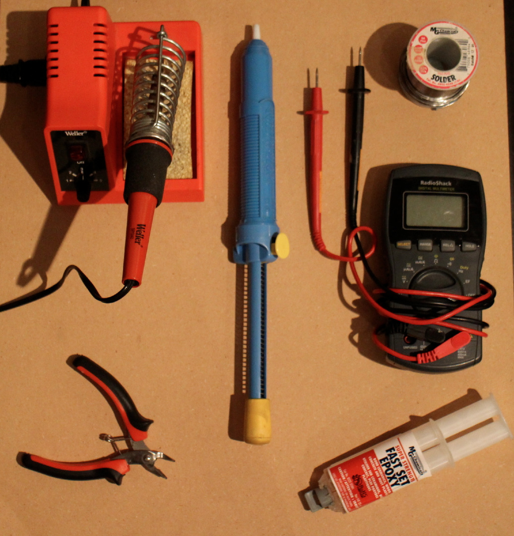
1. Soldering Iron*, Solder & Solder Wick
2. Wire Strippers
3. Epoxy
4. Multimeter
5. Recommended: Breadboard + Breadboard Wires (for setup and testing)
*Note: If you do not have access to a soldering iron, you can twist wires together and coat in hot glue.
Setup Raspberry Pi to Play Music
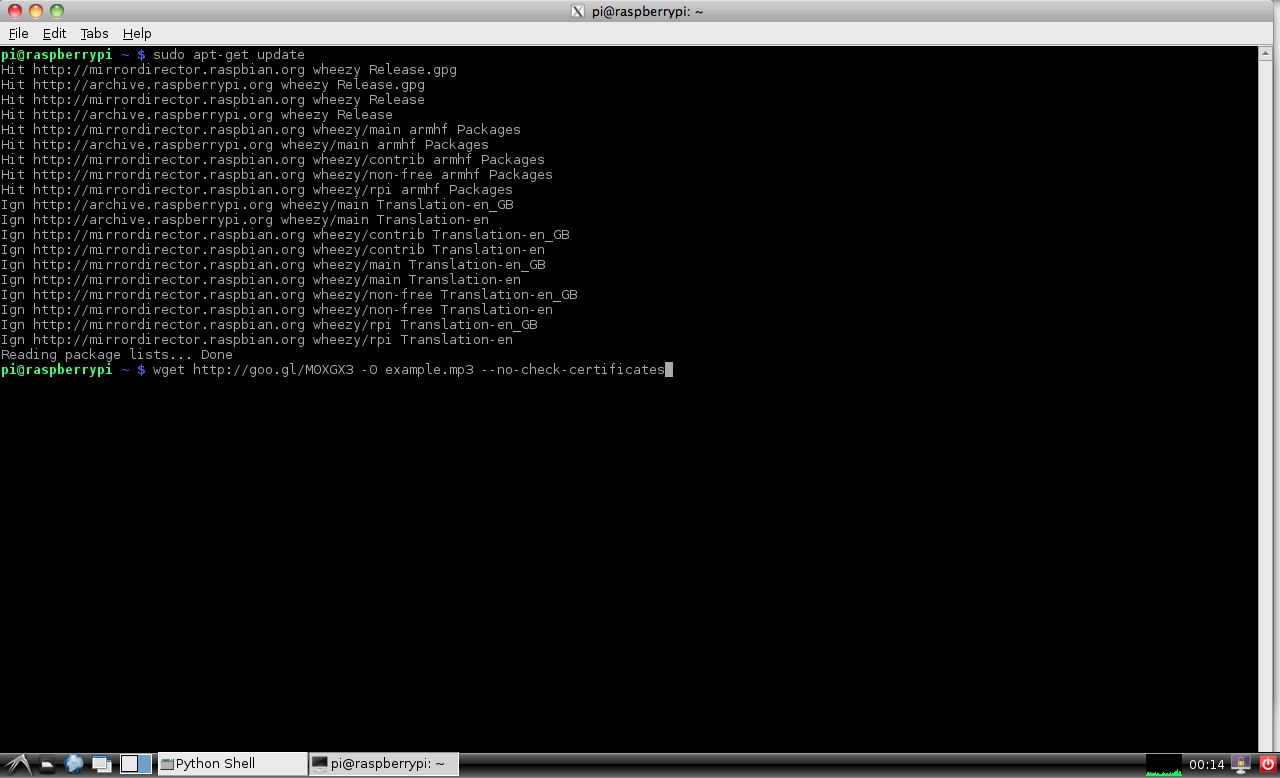
This project provides an overview for how to play a music file saved on the RPi SD card. Possible modifications include setting up the RPi to play music from an external USB drive or streaming music from a website.
1. Install updates.
sudo apt-get update
2. Download example music file for testing.
wget http://goo.gl/MOXGX3 -O example.mp3 --no-check-certificates
Note: This saves the file in whatever directory you are currently in.
3. Open the Terminal window and go into the folder with the music file
Use following command (switch “FolderName” for location of music file):
Cd /home/pi/FolderName
4. Type following command to play file over the audio output:
omxplayer example.mp3
Build It! Pt. 1

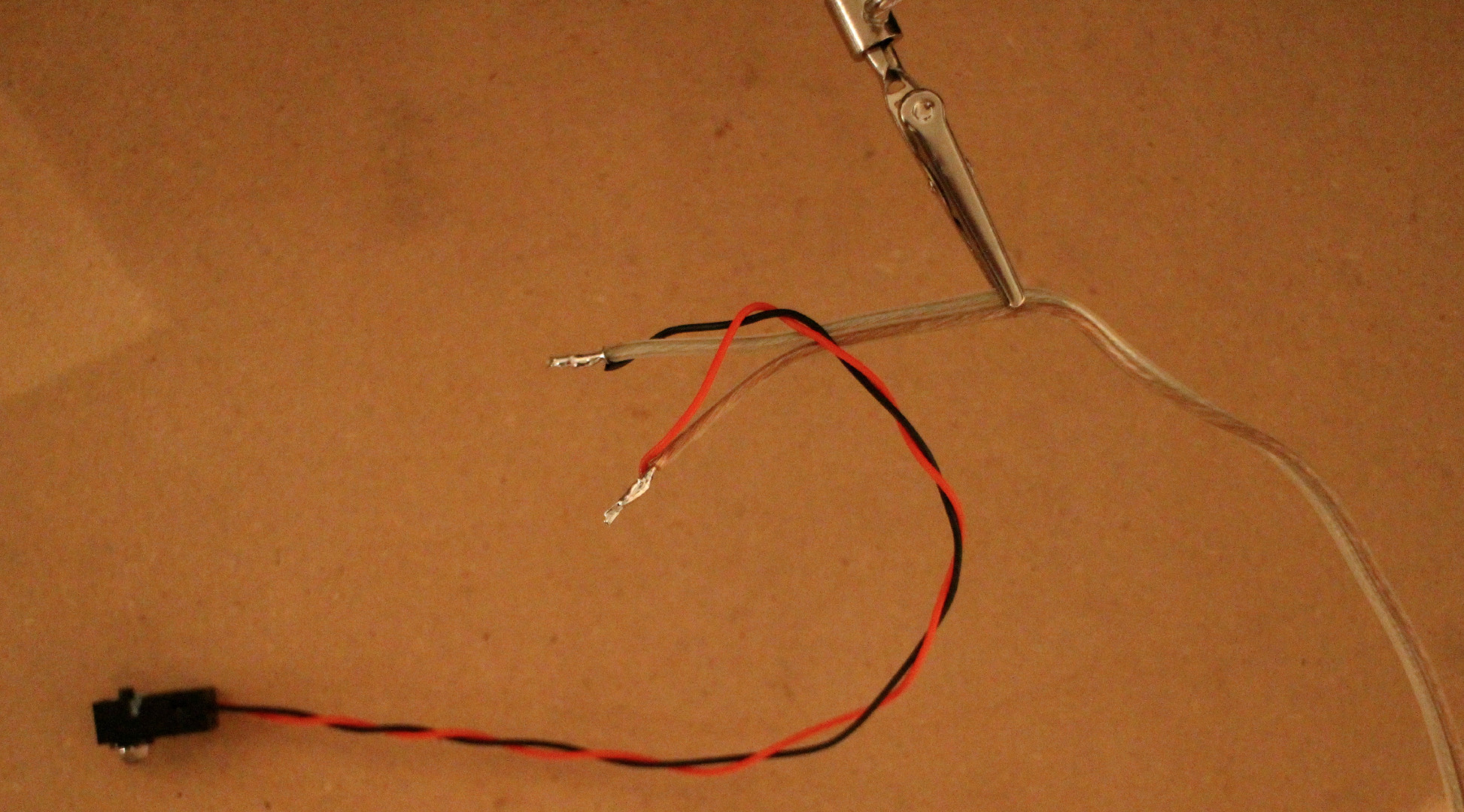
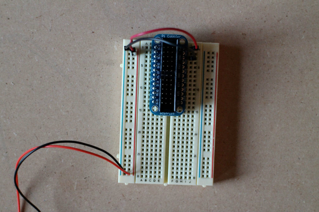
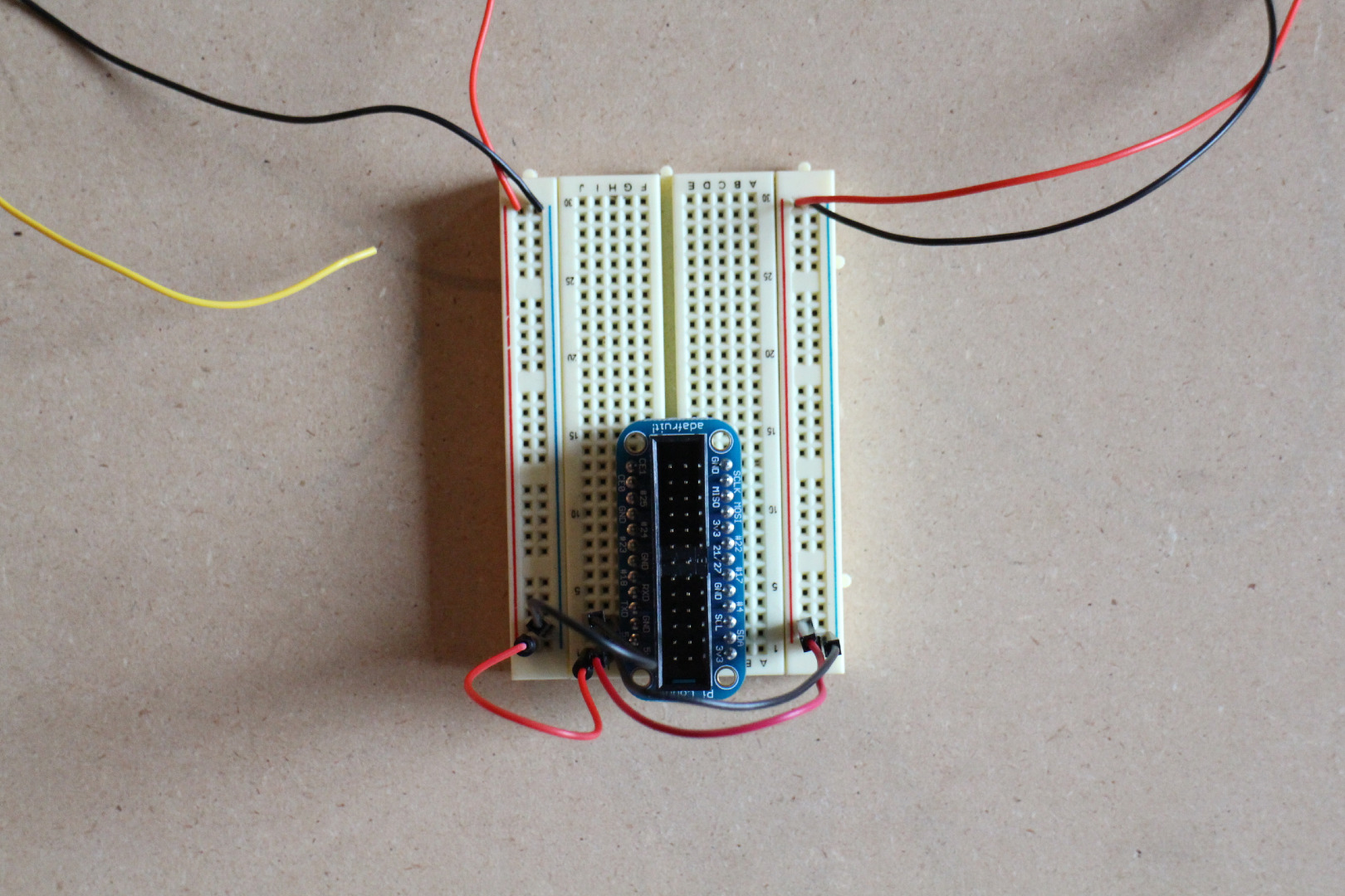
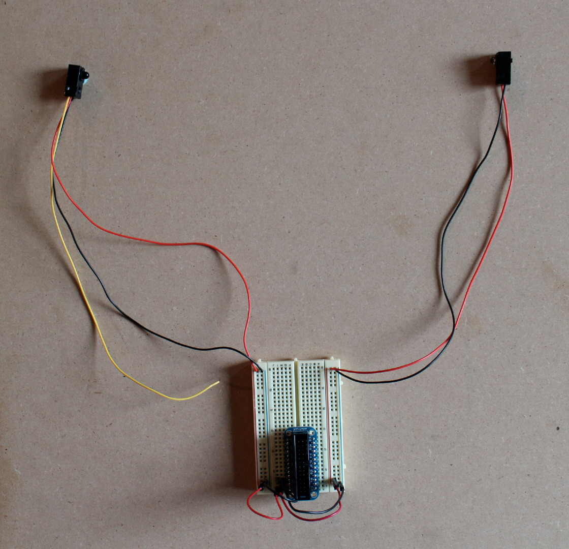
Recommended to build the circuit on a breadboard and test prior to soldering any of the components onto the PCB board.
1. Extend the wire leads of the IR beam (2 wires: red & black) and IR receiver (3 wires: red, black & yellow).
Plan out and measure the route of the wires from where the IR beam and receiver will be installed to the speaker system. At a minimum, make each wire lead 3 - 5 ft.
Recommended to add connectors to the IR beam and/or receiver to make it easier to disconnect them and, if necessary in the future, modify the system.
If the schematic makes sense, skip the rest of the Build it! steps.
2. Connect the positive side of the IR sensor beam to Raspberry Pi 5V pin.
3. Connect the negative side of the IR beam to RPi ground pin.
4. Connect the positive side of the IR receiver to RPi 5V pin.
5. Connect the negative side of the IR received to the RPi ground pin.
Build It! Pt. 2
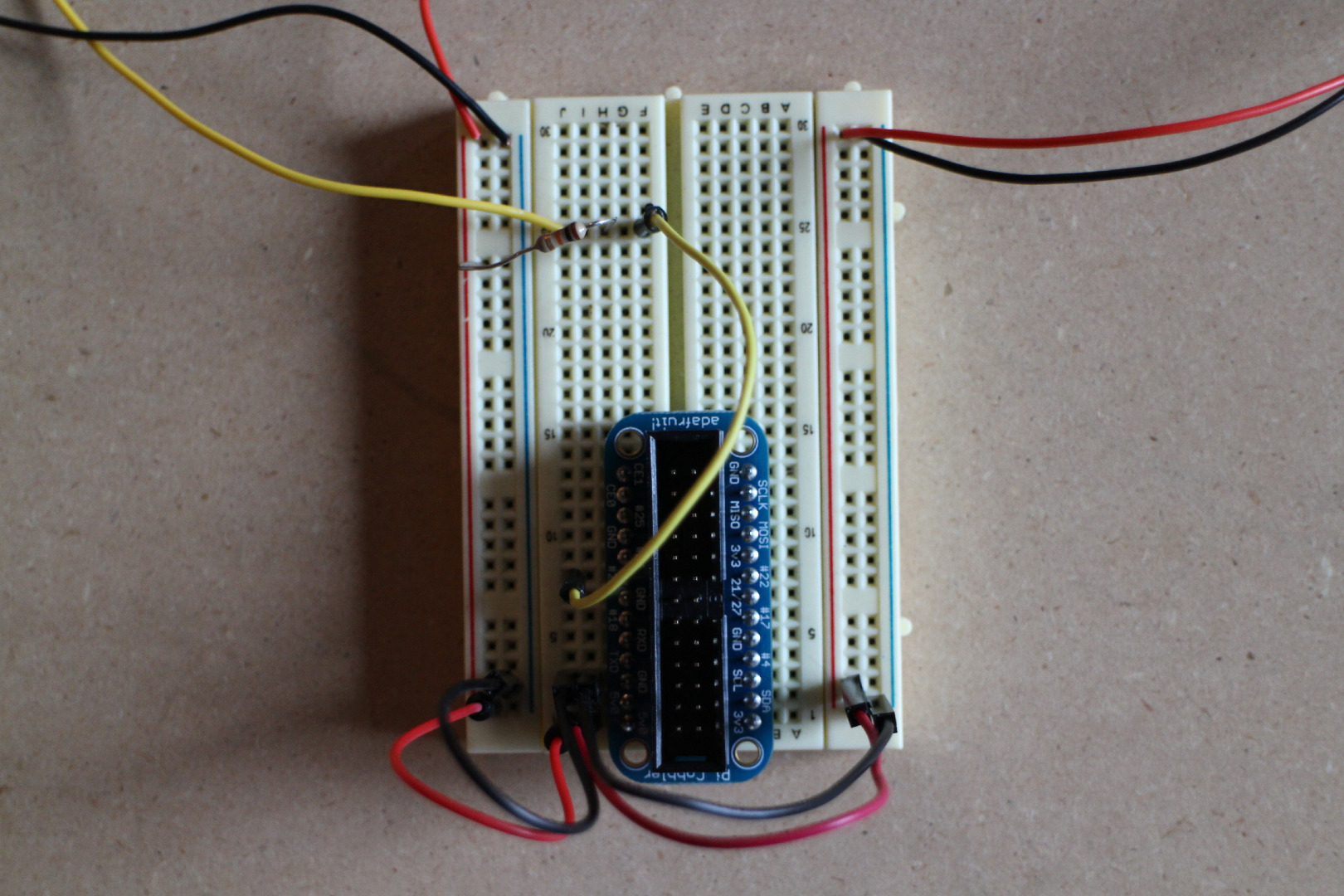
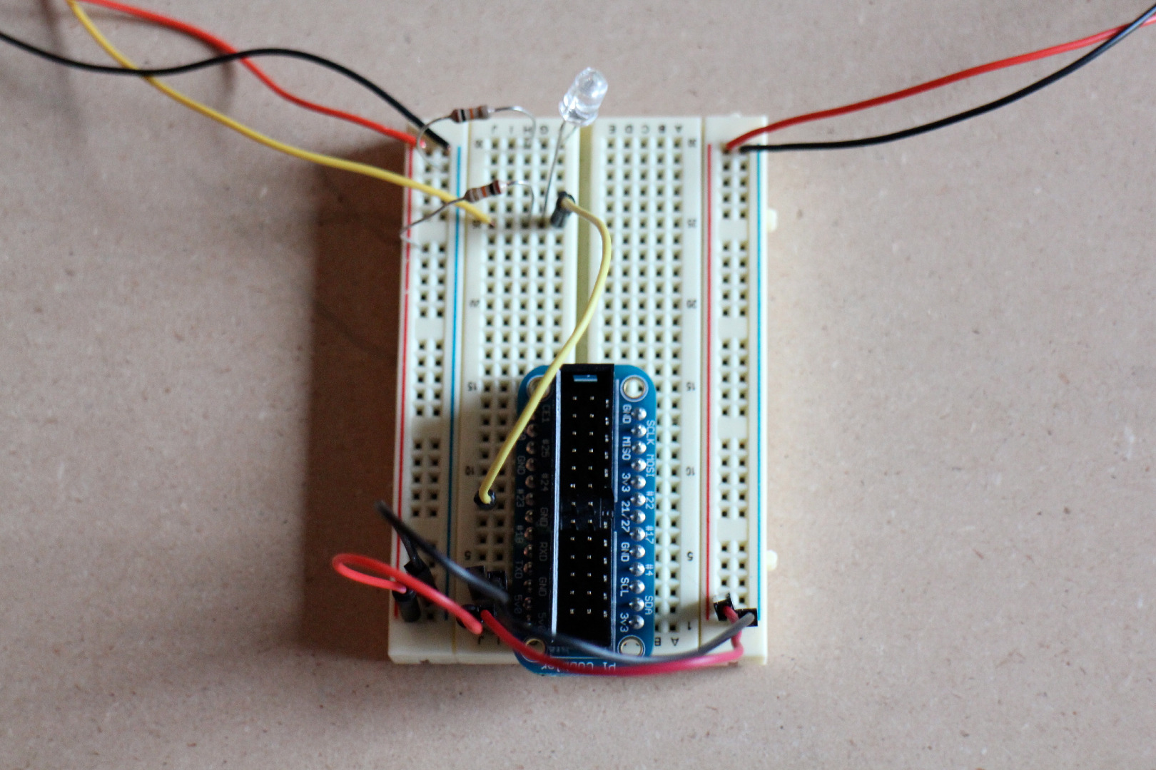
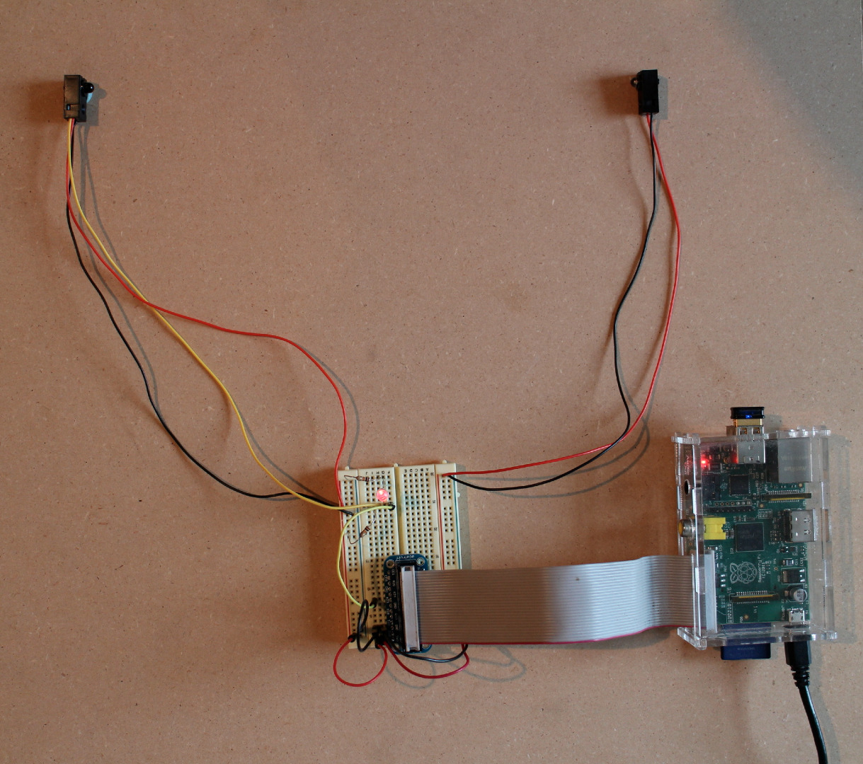
1. Connect the data pin (yellow wire) of the IR receiver to RPi GPIO pin 23.
2. Connect the 10kOhm resistor between the data pin/RPi GPIO pin 23 and the RPi 5V pin.
3.Recommended: Connect an LED + resistor across the IR receiver data pin (yellow wire).
Connect the positive LED leg to the IR receiver data pin. Connect the negative LED leg to the resistor. Connect the other side of the resistor to ground.
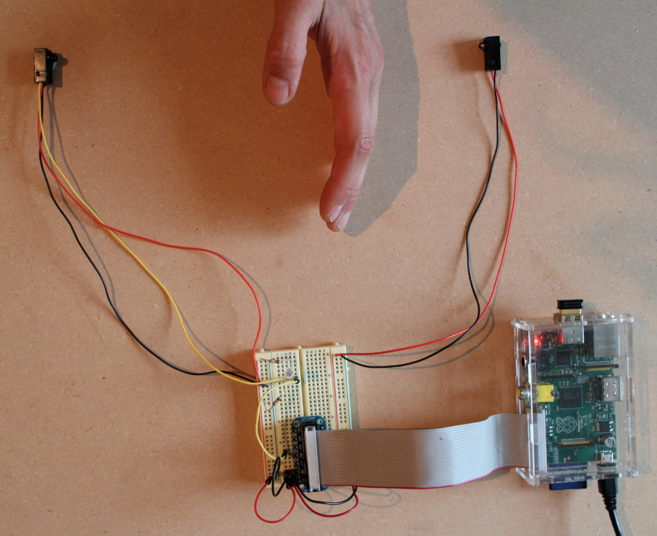
4. Plug in RPi and log in; check that IR beam turns on.
If you've connected the LED, it should turn on when the IR receiver gets the signal from the IR beam. Check that the LED turns off if you interrupt the beam.
Code It! Pt. 1
The following is a basic program to play a song when the IR beam signal is broken (AKA when you walk between the IR beam and IR receiver).
Here's a link to the github code.
Save the song of your choice to an easy-to-remember-and-type folder, in this example I used "FolderName" to designate the title of the folder in which the mp3 is saved.
Note: This program prints a message to the screen each time the song is played. This worked for my needs, as I wanted to have a log of each time music is played, but of course this code is just an outline of what is possible. Modify it to suit your needs. Also, please note that the spacing may be off; this is important in Python so be sure to "tabify" your code before running it and check that the spacing is consistent.
#DIY Motion Triggered Music Player
import time
from threading import Thread
import RPi.GPIO as GPIO
import subprocess
class AutoTrigger():
def call_omxplayer(self):
print ("playing " + self.file_path)pid = subprocess.call(['omxplayer', self.file_path], stderr=subprocess.PIPE, stdout=subprocess.PIPE)
self.is_running = False
def play_song(self):
if not self.is_running:
self.song_thread = Thread(target=self.call_omxplayer, args=())
self.song_thread.start()
self.is_running = True
def __init__(self,pin, file_path):
self.pin = pin
self.file_path = file_path
self.is_running = False
GPIO.setup(pin, GPIO.IN)
'''
This is a hack (the callback) thanks for python closures!
'''
GPIO.add_event_detect(self.pin, GPIO.FALLING, callback=lambda x: self.play_song(), bouncetime=10)
def main(): GPIO.setmode(GPIO.BCM)
AutoTrigger(25, '/home/pi/FolderName/SongName.wav')
AutoTrigger(24, '/home/pi/FolderName/SongName2.mp3')
print ("Ready: !")try:
while True:
pass
except KeyboardInterrupt:
GPIO.cleanup()
if __name__ == '__main__':
main()
Install It!
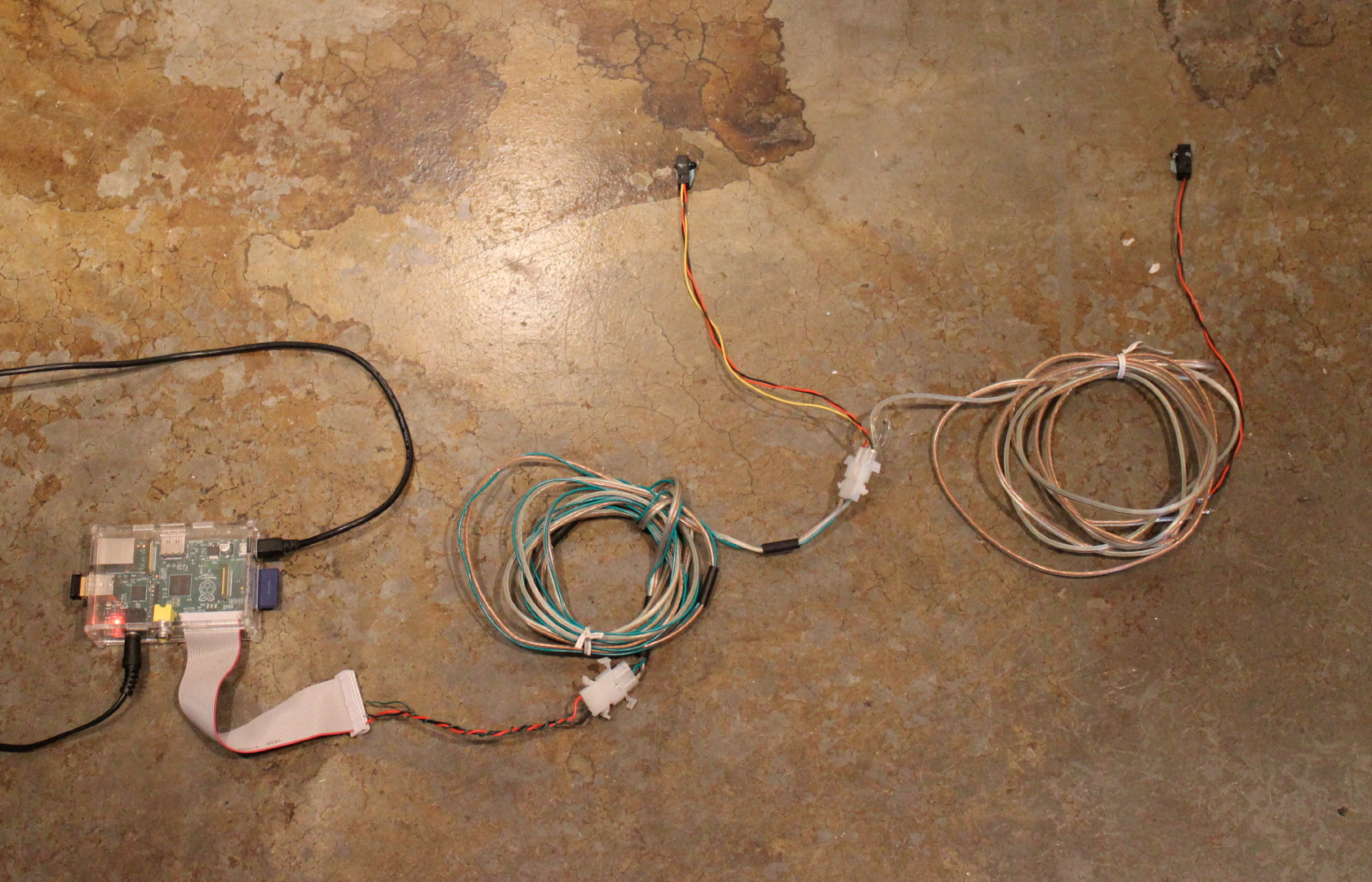
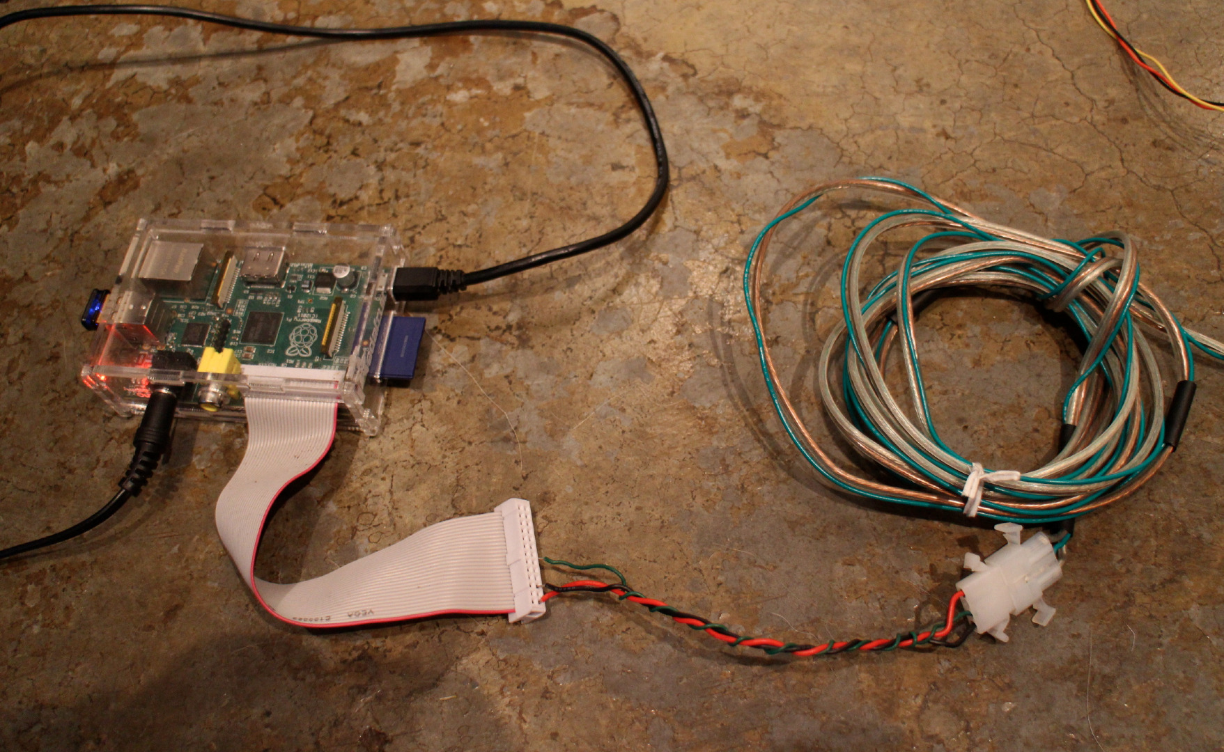
1. Check system for functionality. If system works as expected, coat all exposed electrical connections (except for RPi plugs) in hot glue or epoxy.
Be aware that epoxy is essentially permanent; use hot glue if you want to modify the system in the future.
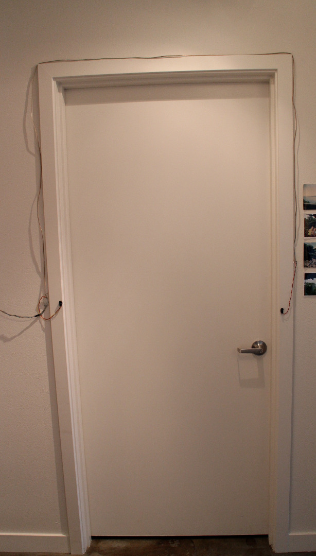
2. Attach the IR beam to one side of your front door frame, and the IR receiver on the other side of the door frame, directly in line with the beam. Run the wires up and over the door frame.
It is somewhat tricky to align the IR beam and receiver; highly recommended to use the LED + resistor to quickly see when the beam and receiver are aligned. Use sticky tack or tape to help w/ alignment.
Secure the IR sensor via thumbtacks, nails, screws, etc. Suggested to run the wires up and over the door frame (instead of on the floor).
3. Place the RPi in a convenient and out-of-the-way location.
Consider where you want to place the speakers. If you need longer wires, measure the needed distance and solder in additional wires to the RPi power, ground and GPIO pins.
4. Set up the speakers.
5. Test!
Plug in the RPi and trigger the system to be sure that the music plays when you walk through the IR beam.
Activate and Enjoy!
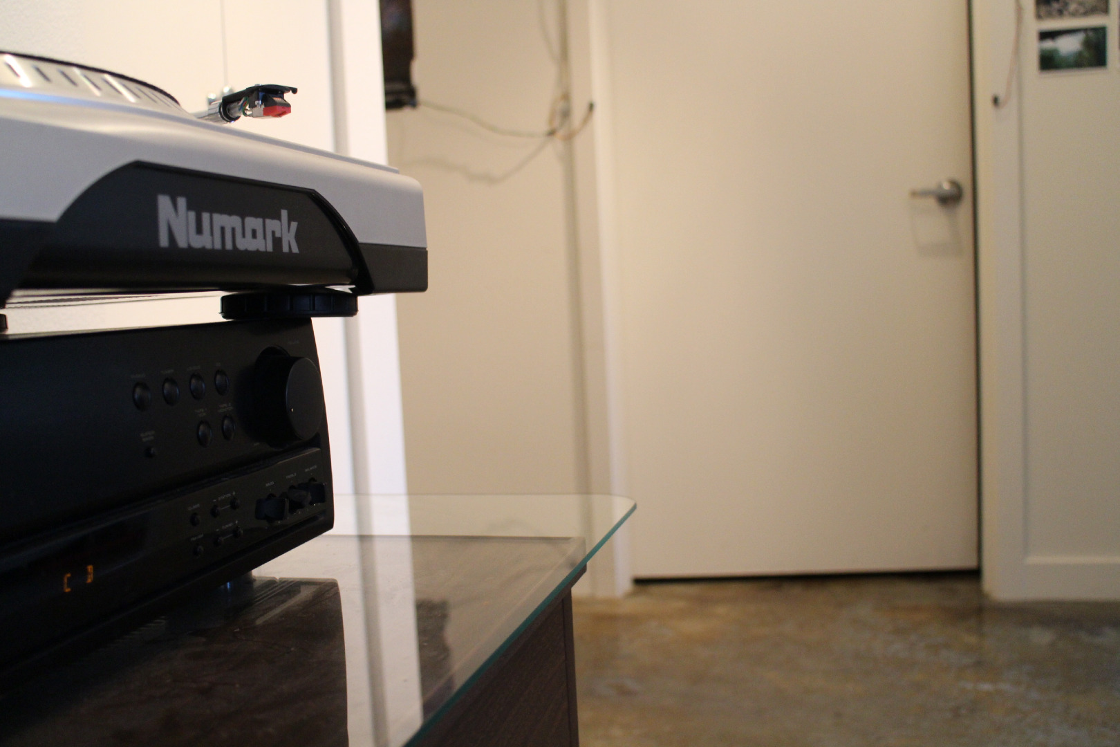
The only issue w/ this design is that the IR receiver range is shorter than I originally wanted, only about 2 feet. Some solutions to this problem would be to use a lens to magnify the IR beam or increase the power input.
Possible modifications of the project include using WiFi to stream music or podcasts, triggering lights, and/or using it to detect motion in and out of your home for a basic security system.. or to see how many times your cat leaves the house while you're gone.
Thanks for reading! Please subscribe and check out my YouTube channel for more projects and other cool science stuff.
Happy building!