Motion Controlled Mouse Trap
by JasmehSudan in Circuits > Arduino
258 Views, 1 Favorites, 0 Comments
Motion Controlled Mouse Trap

Have a rat problem but don't want to deal with the moral consequences of murdering another living creature? Well, I Jasmeh from Irvington High School, have created the Motion Controlled Mouse Trap. This smart rodent snatcher can solve your issues in one swift motion.
Special thanks to Product Design Online for helping me design the hinged box and also to ROBO HUB for giving me the idea, providing a list of materials, and giving me the skeleton for the code. I would also thank my Principles of Engineering teacher Ms. Berbawy and her non-profit organization Berbawy Makers for providing me with the materials and tools required to build this project.
Supplies


Materials:
- Rectangular plastic container
- Mini Breadboard
- Arduino Nano Every
- Jumper Wires
- Ultrasonic Sensor
- Micro Servo
- Phillips Flat Head Stainless Steel Machine Screws
- CAD Files
- Stainless Steel Machine Screw Nut
- Spray Paint
- Magnets
- Power Bank
- Large Paperclip
- Pencil or Pen
- USB to Micro USB Cable
Tools:
- Hot Glue Gun
- Original Prusa i3 MK3S+ 3D printer
- Needle Nosed Pliers
- Screw Driver
- Power Drill
- Caliper (or other measuring tool)
Applications:
- Arduino IDE
- Autodesk Fusion
- Prusa Slicer
- Tinkercad
CAD


To begin, let’s build the home for the machine that will catch these disgusting little creatures.
Base Sketch:
In Autodesk Fusion, we’ll design the bottom lid, making sure that the size of the lid doesn’t exceed that of the plastic container. The bottom lid will house the servo, sensor, breadboard, and part of the power bank so make sure to give enough space for them and create appropriately sized walls. Keep in mind that you also need space for wires. Luckily the recommended screws are countersunk screws meaning that when attaching them, the floor will remain level. This allows you to place the screws inside the spaces for the breadboard, power bank, and other holders.
Creating the Bottom Half:
Next, we’ll extrude the sketch to about half the height of the power bank (remember to account for tolerance). Then we’ll extrude the walls and create holes for the screws and sensors. In regards to the spaces for the components themselves, make sure that the walls aren’t too high or too short, so they keep the components secure while not interrupting them.
Creating the Top Half:
Mirror the bottom half and make sure to remove the unnecessary holders from the top half (servo, sensor, and power bank holders). Follow the tutorial by Product Design Online to create the Hinges. So the box can open and close with ease
Recommendations:
You should do test prints to test whether the tolerance you have chosen works and can also use it to test whether the box works. In the future, you may want to implement some kind of cable manager in your CAD to help organize your cables
Keep in mind while creating your design that tolerance should be accounted for so the objects can fit together. For my project, a 0.3 to 0.44mm offset was sufficient.
Circuitry
Using Tinkercad, you can create a diagram of the final circuit. Link to my circuit design on TinkerCAD
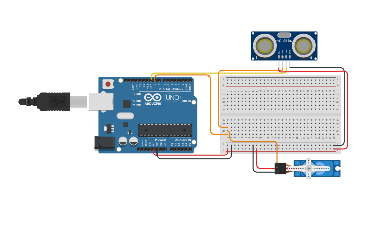
After using TinkerCad to test out the circuit go ahead and create the actual thing.
Connect the D10 port to the trig port in the senor. Connect the D9 port to the orange wire of the servo and the echo pin of the sensor
The 5v port and GND port represent power and ground respectively (positive and negative)
Recommendations:
Use short wires to keep things organized.
Code

Using the code I created, you can program the servo to move when the sensor detects something.
Code explanation:
At the beginning of the code, we initialize the variables by first telling the code where the pins are connected. We also a variable called “counter” to solve an issue where the sensor starts detecting random distances (for example, sensing 12 cm but suddenly 3cm randomly)
The setup function behind the code assigns the assigned pin positions to their respective components while also setting the servo up into position.
The measure function is the function that gets the distance from the sensor
The loop function loops the code infinitely and only starts moving the servo when the distance detected is less than 12 cm (can be set to whatever you want) more than 4 times. This was to prevent random glitches or false readings to not activating the trap.
Downloads
Setting Up


Before we begin assembly, we’ll need to prepare our components.
The Container:
Step 1: Mark the areas you need to cut out
Step 2: Cut the lid area to make an entrance
Step 3: Use a power drill to drill holes for the screw holes and the sensor
Step 4: Attach 2 magnets to the bottom corners of the door and the body so the box stays shut during closing
The Cap:
Step 1: Using hot glue, attach the pencil/pen to the cap
Step 2: Spray paint the cap to make it look better
The Pin:
Step 1: Using the pliers, shape the pin to be able to hold on to the pen, keeping the cap on
Assembly

Place the components into the component holder you have printed out, Screw in the holder
Place the open onto the servo arm. Pull the lid back and attach the pin to the pencil to test it out!