Motion Activated Cosplay Wings Using Circuit Playground Express - Part 1
7391 Views, 87 Favorites, 0 Comments
Motion Activated Cosplay Wings Using Circuit Playground Express - Part 1
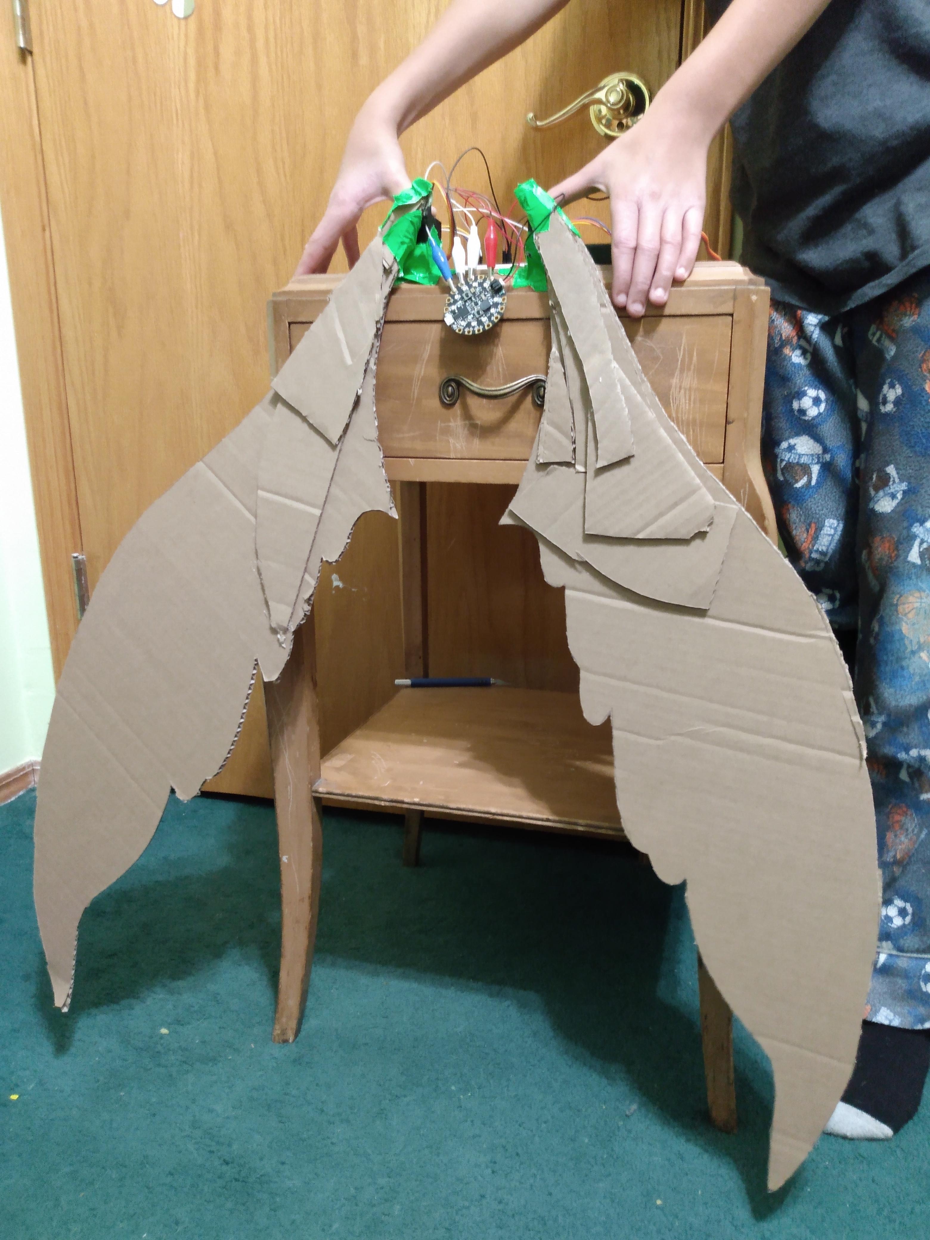
This is part one of a two part project, in which I'm going to show you my process for making a pair of automated fairy wings.
The first part of the project is the mechanics of the wings, and the second part is making it wearable, and adding the wings themselves.
This is part one, the bare mechanics. Once you're done with this part, you can move on to Part 2!
SUPPLIES
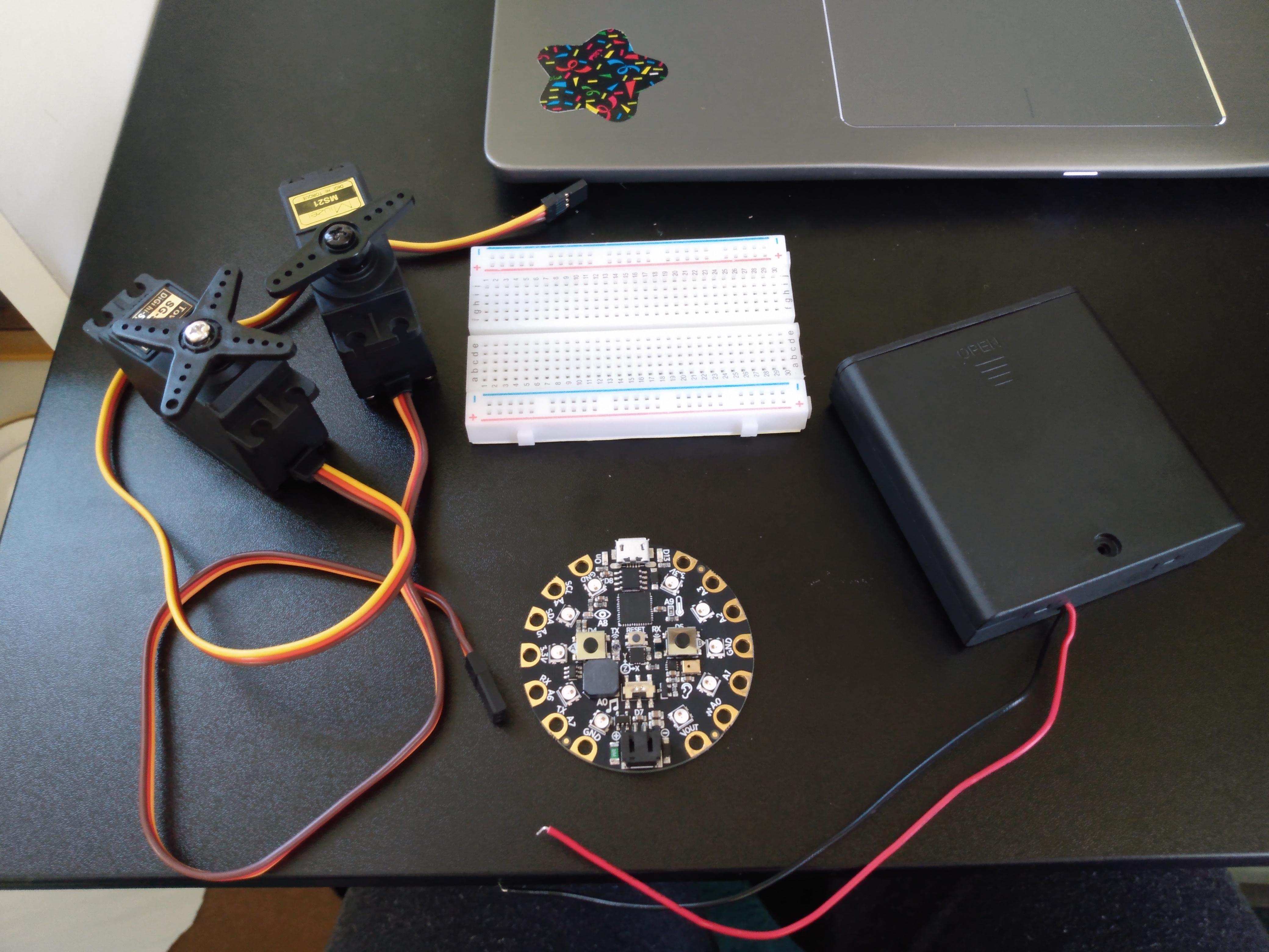
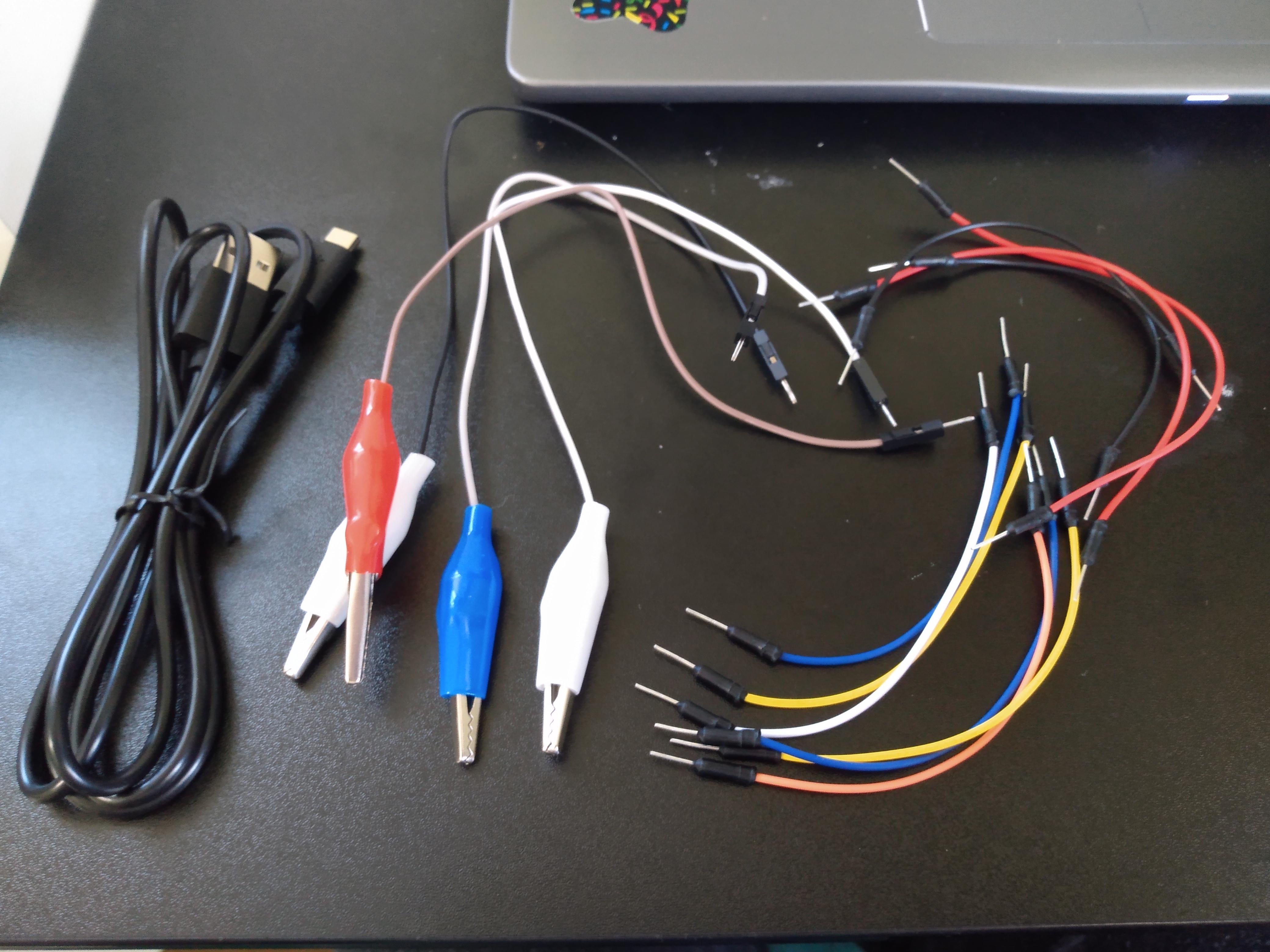
For this part of the project, you will need:
- 1 x Circuit Playground Express
- 2 x Standard servo motor
- Breadboard (no-soldering for testing)
- Power source (I used a 4xAA Battery holder, but you can use whatever works for you)
- USB to micro USB chord
- 4 x Alligator clip to male header
- Wires (with male headers)
The following supplies are optional, and for making prototype wings to test out your project:
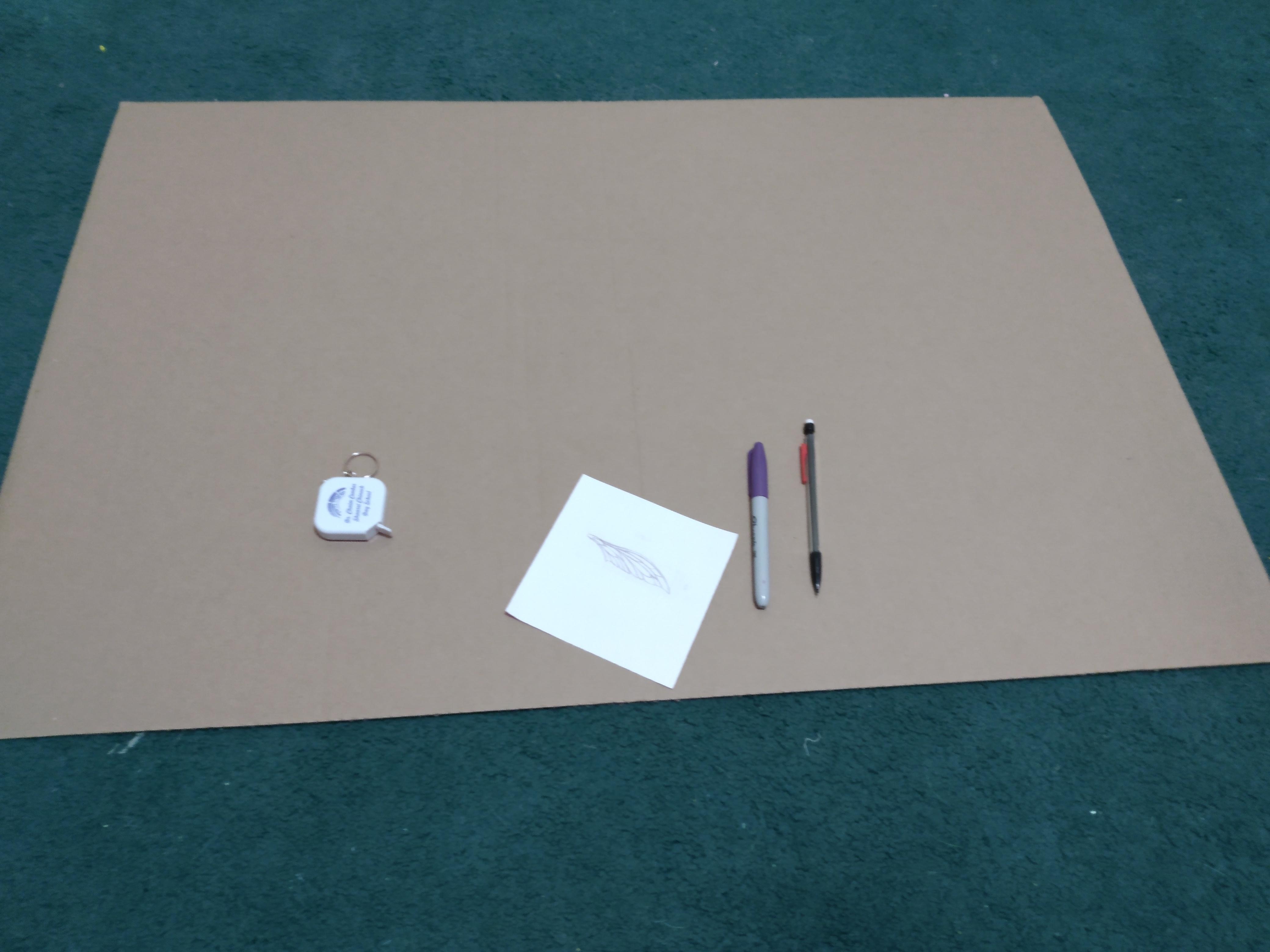
- Paper bags or Cardboard
- Pencil
- Sharpie/marker
- Popsicle sticks
- Tape or hot glue
- Scissors or X-Acto knife
Accelerometer Code for the CPX
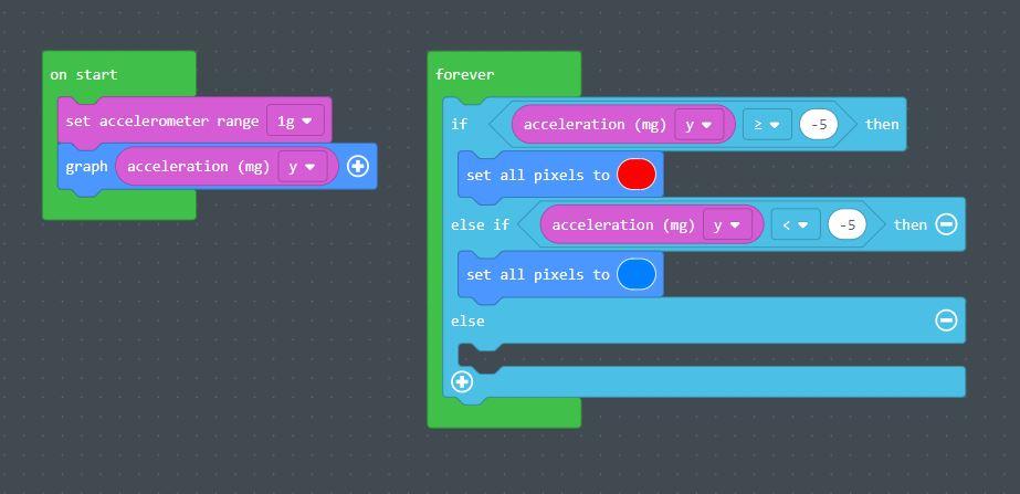
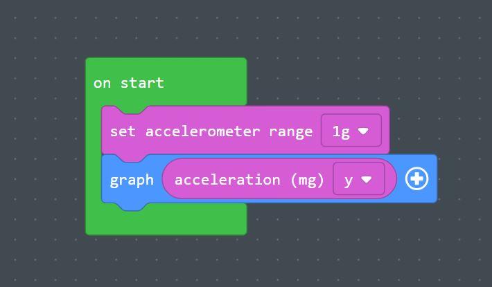
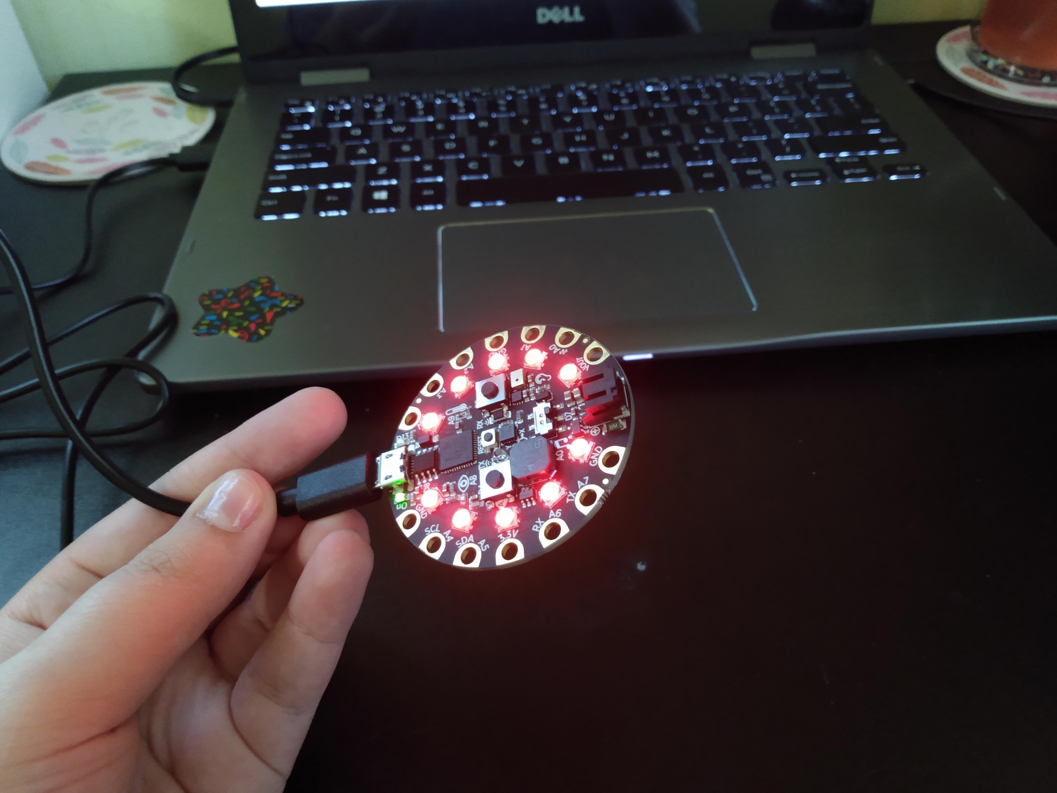
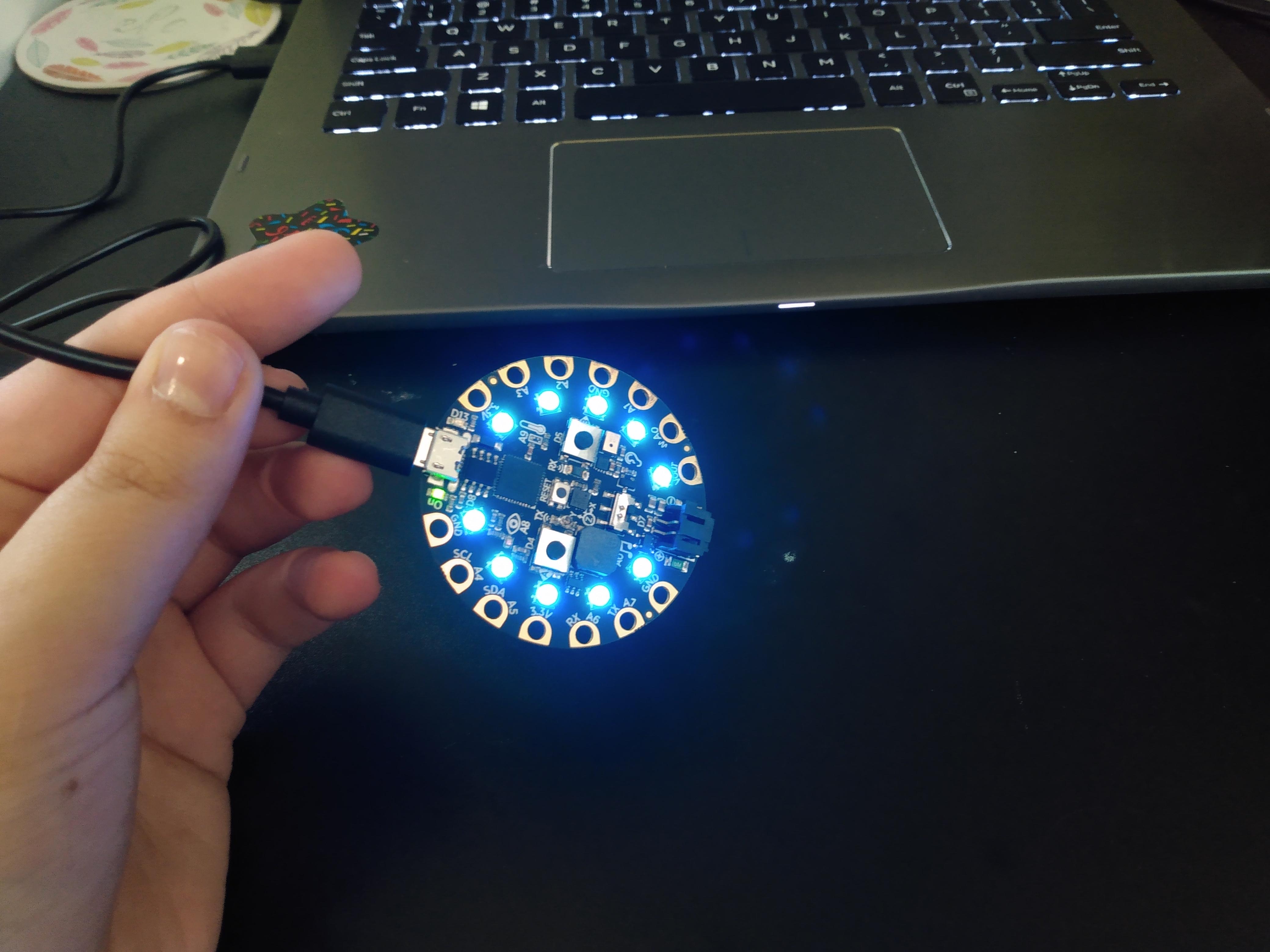
First, you need to set up the Circuit Playground's accelerometer, because the wings will move according to the movement of the hand.
Now, if you're doing this project, you can experiment with sound, light, any number of factors that cause the wings to move in a more natural fashion than systematically up and down or side to side. For this project, however, I chose to have the wings move with your hand: when the hand points up, the wings go up, and vice versa.
For the sake of clarity, we're going to use the neopixels to help us identify whether or not the CPX code is working properly. Be sure to save this project throughout the process, or you will need to restart from wherever it auto-saved last, which I found particularly frustrating.
Begin with a new MakeCode project. The title can be anything you want, but I suggest something relating to motion-activated wings so it's easier to find later. Don't remove the forever function. Create the starting program by taking an "on start" block, and adding an accelerometer setting and a graph function. The graph function with the accelerometer records the position of the CPX in relation to the ground using gravity.
Once that's set up, we need to give the accelerometer readings a purpose. As I mentioned, in part 2 of this project the CPX will be attached to the back of the hand, and when the hand points upward, the wings will "unfold," and downward will cause the wings to "fold". So, in the forever block, add two "if" functions, and replace the "true" option of both "If" blocks with an inequality, on the left being the accelerometer measurement of Y. You can play around with the settings pictured above, but the block for when the acceleration is greater than a number will be your "down" statement, and the "less than" "if" block will be your up statement. Just so you know that the accelerometer is working, have the color of the neopixels change color when the CPX moves. In this example, I used red for down and blue for up.
Upload the code to your CPX by hooking it up to your computer with the USB cord, and make sure the colors work the way you planned them to. If adjustments are needed, feel free to make them.
Add Servo Code
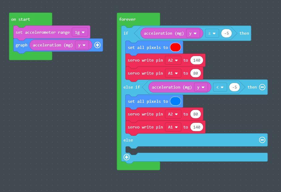
Once the colors work the way you want them to when you tilt the CPX, go back to the code, because now we're going to add the servo motor commands.
Go to the Advanced tab in the block menu, and under Pins, find the servo blocks. Place two "Servo write" blocks in each of the if statements with the Neopixel commands, and set them to your minimum angle (the lowest your wings will fold), and your maximum angle (the highest the wings will lift). I used the angles 140 and 80 as shown for experimentation, since this is approximately the angle I want the wings to move.
One "Servo Write" block in each "if" statement will be for your right wing, and set to pin A1. This means the right wing will be wired to the A1 pin on your CPX, and will move according to the corresponding servo command. The "up" servo command for the right wing will be your larger number, 140 degrees in my example. The lower value, 80 degrees, is your minimum angle for the right wing and will be in the down function, also set to pin A1. Switch these values for the left servo/second servo write block in each statement, connected to pin A2 (140 for down, 80 for up). Remember to save your work!
Connect Servos to CPX
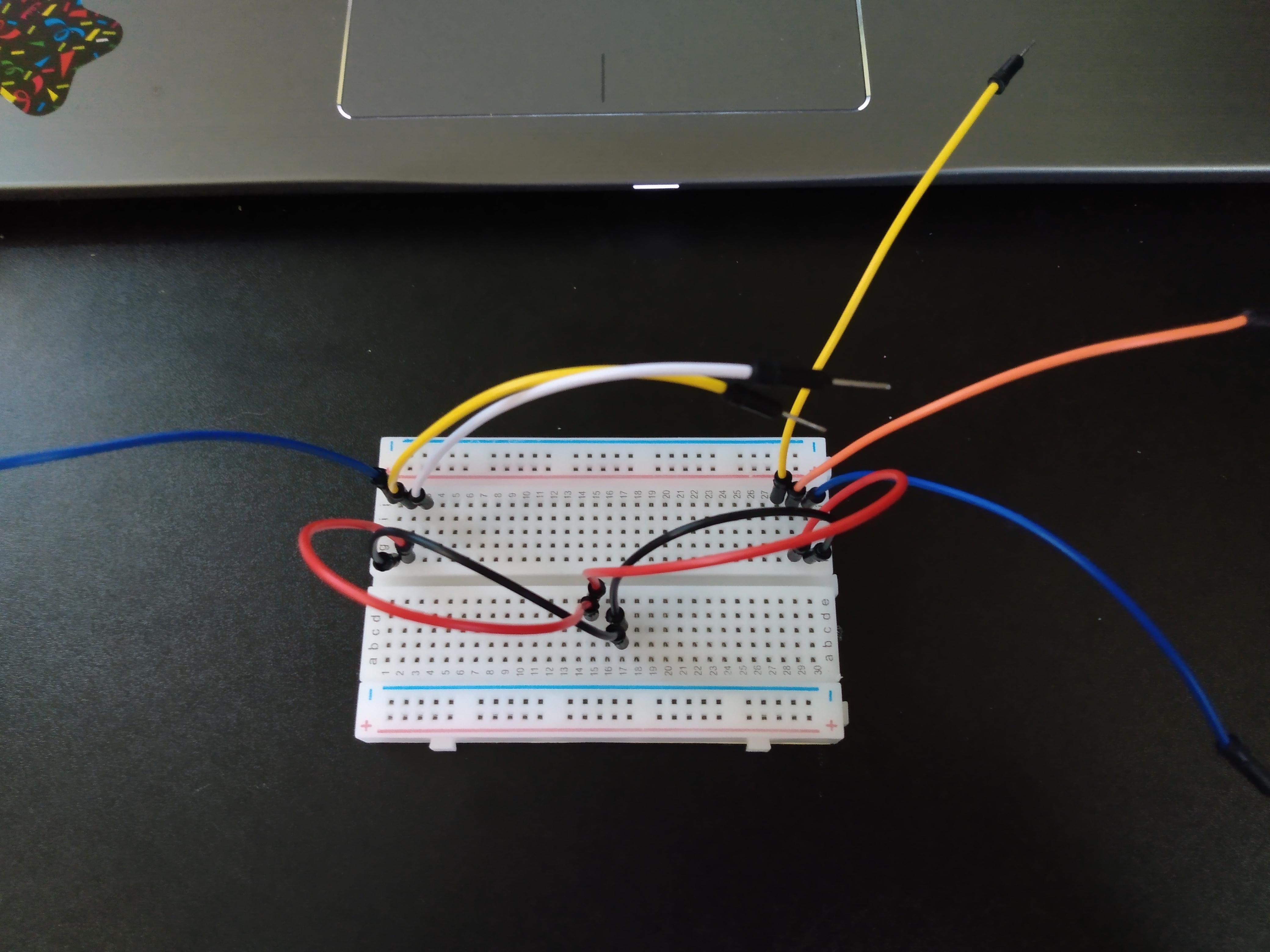
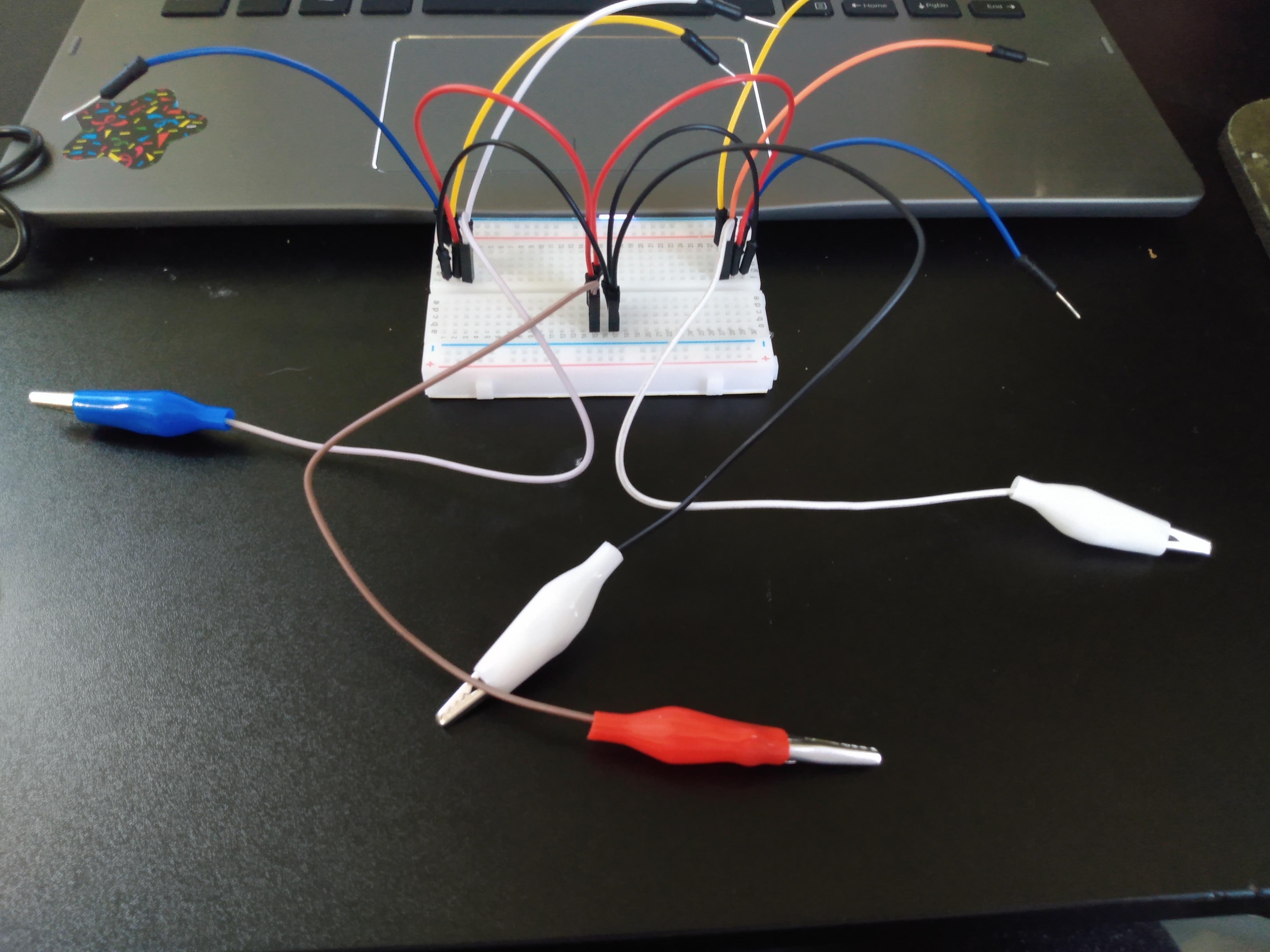
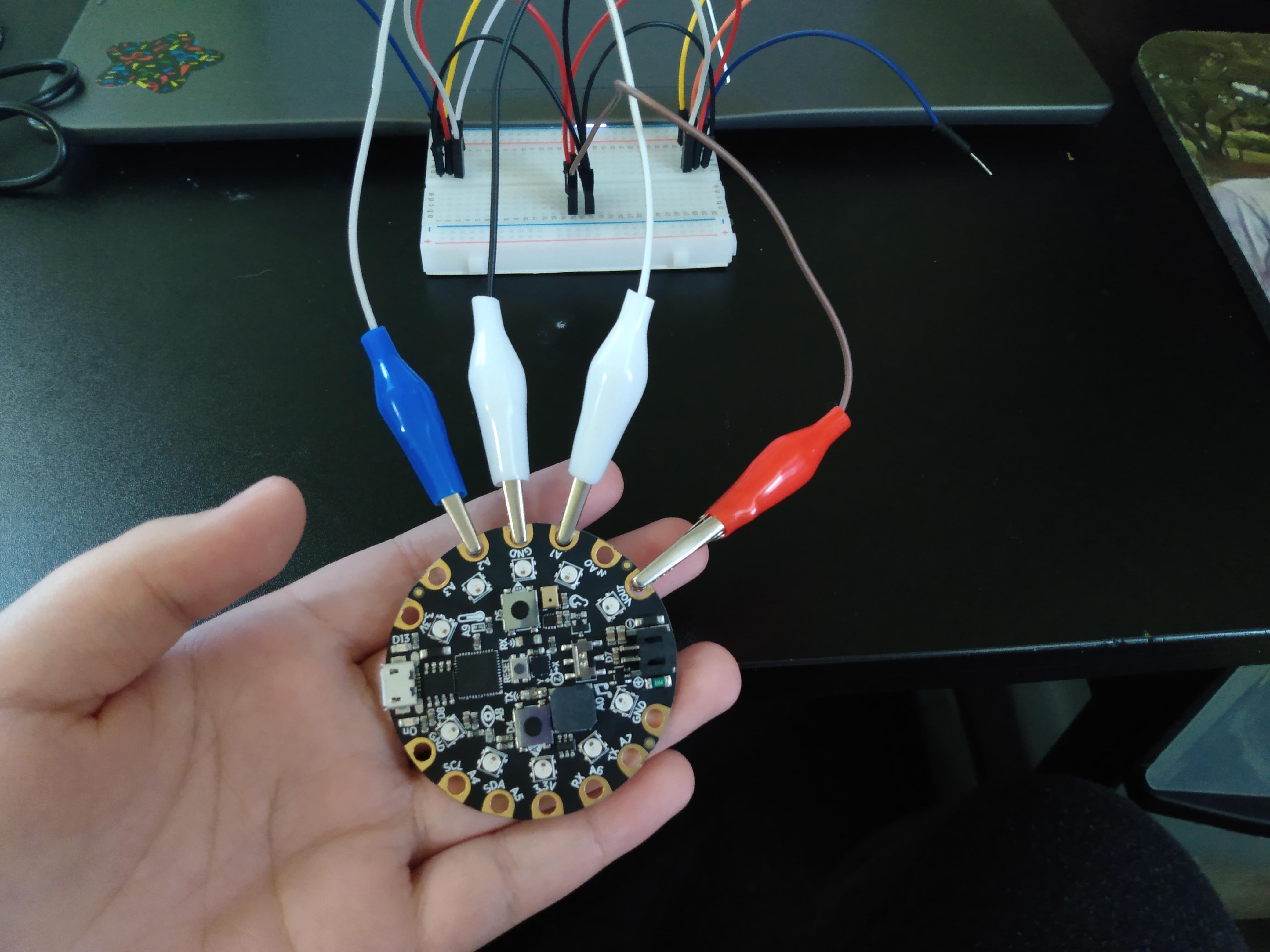
Set the code aside for a moment, and let's build the mechanics for the job.
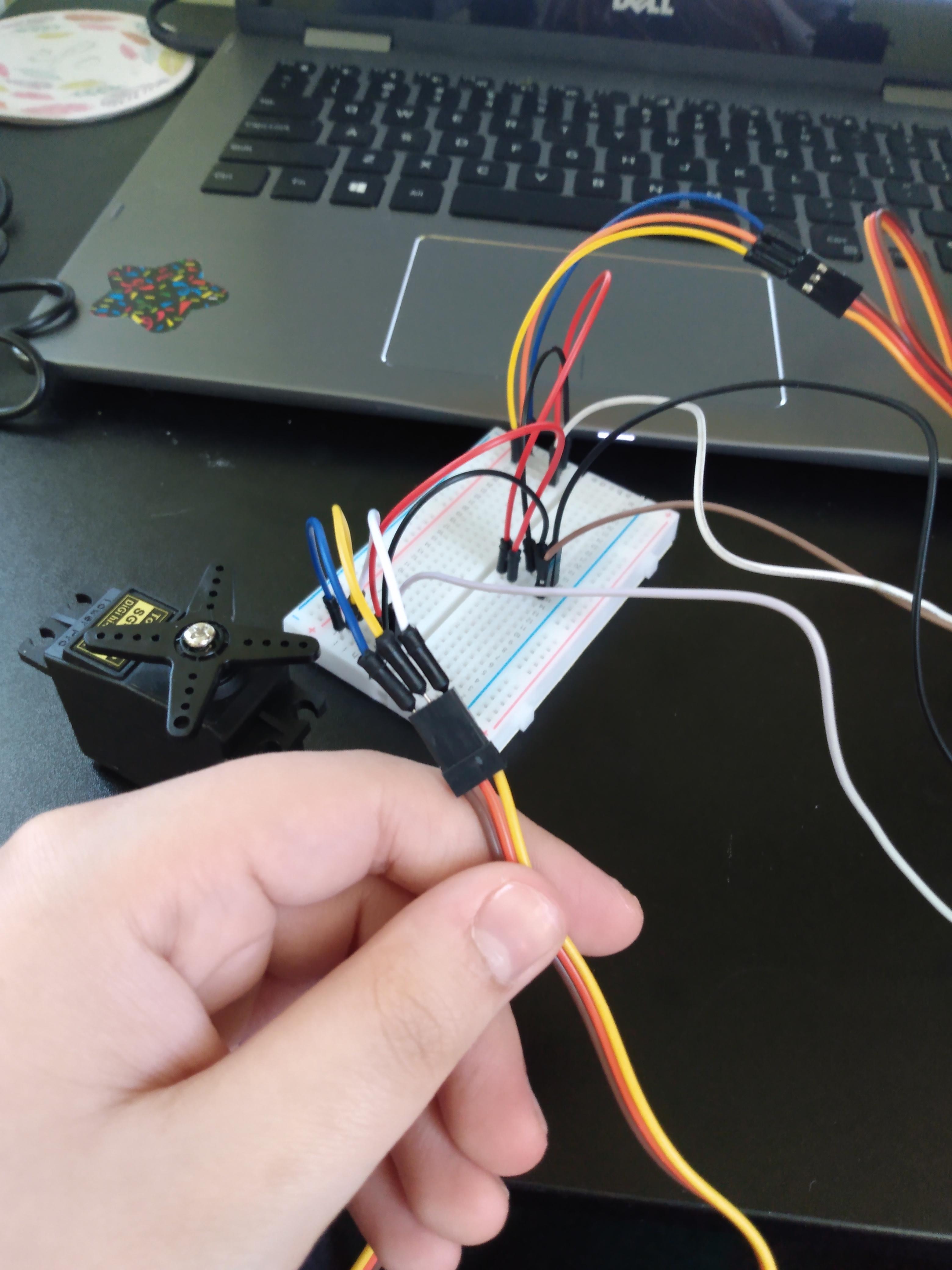
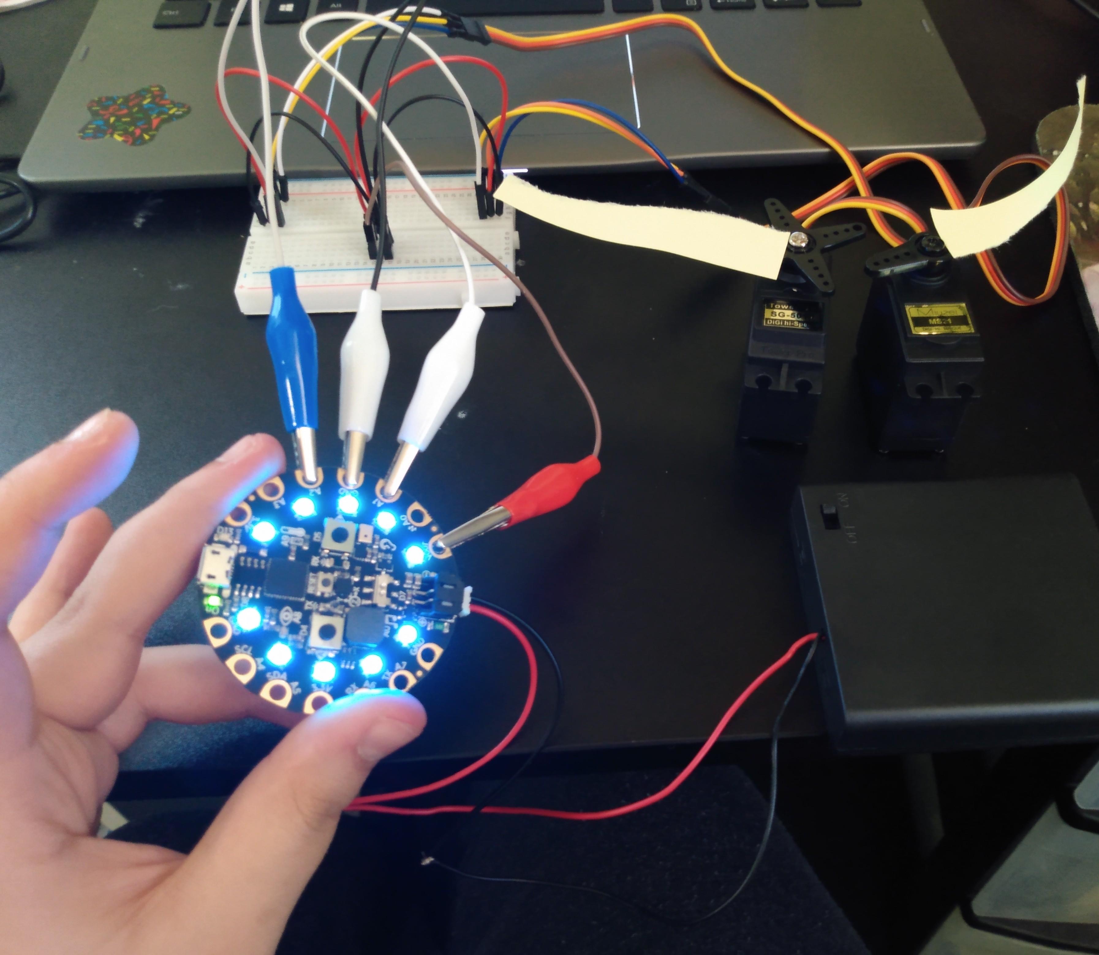
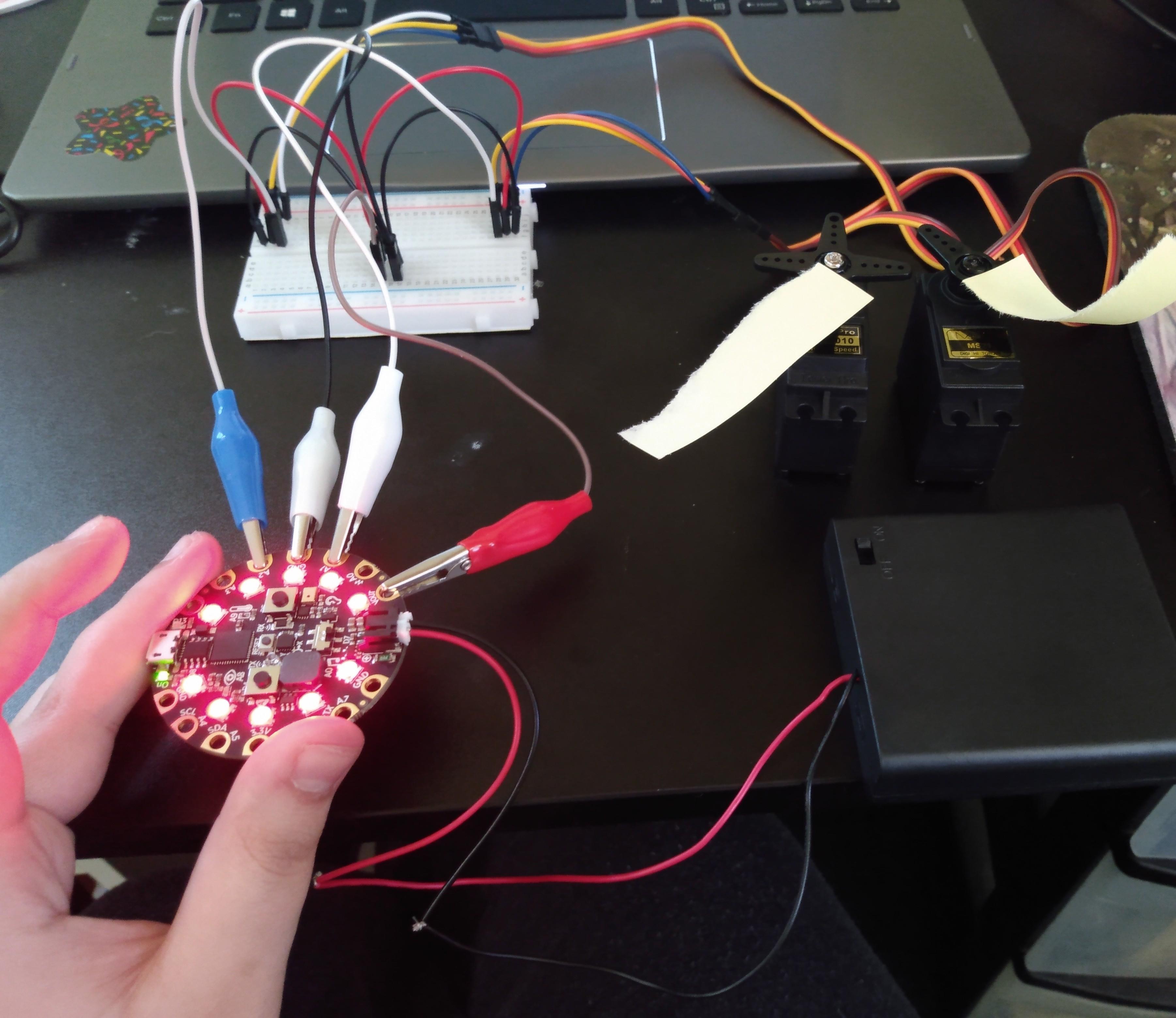
Using your solderless breadboard, connect the wires and alligator clips as shown above. This is how the wiring will work in part 2 of this project, just using less wire to be more compact.
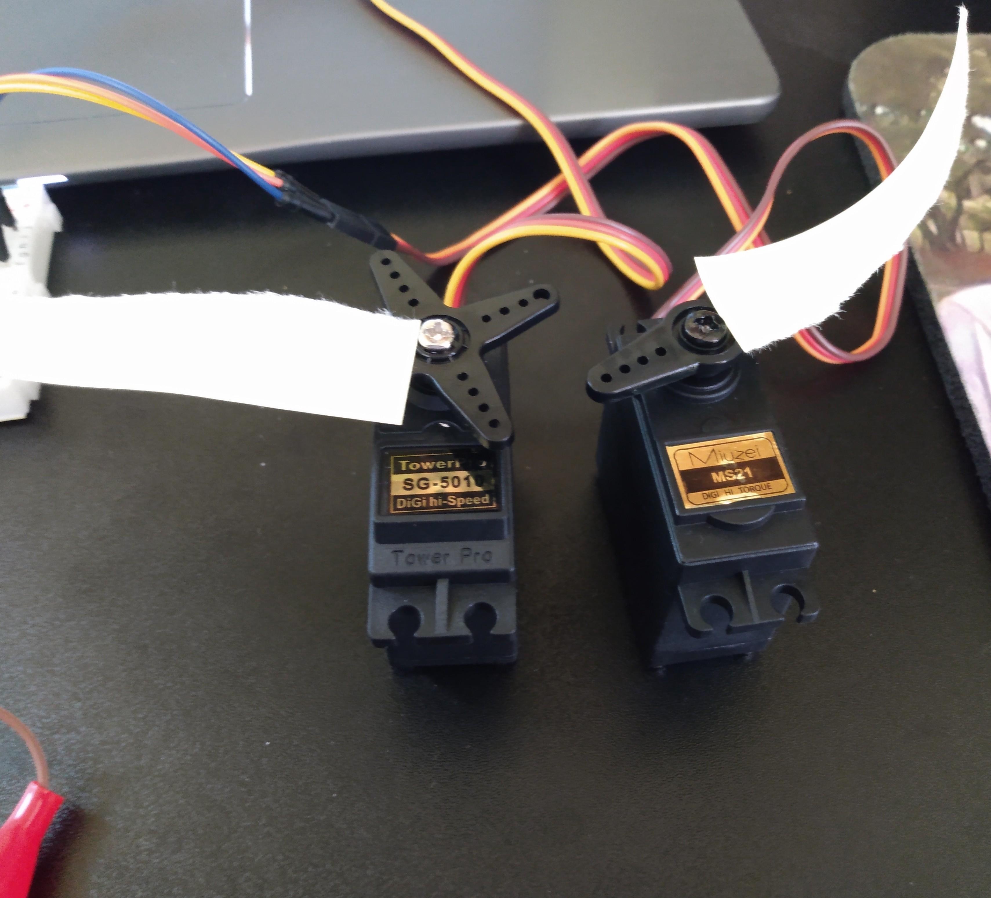
Connect the servo motors accordingly, and using the alligator clips, attach to the CPX as shown above. Remember to attach the alligator clip connecting to the right servo motor on A1 and the clip connecting to the left servo motor on A2, or otherwise according to your code.
Add "flags", or some sort of indicator to your servo motor to make sure they turn in the right directions. You don't need anything fancy, I used a sticky note.
Download the code to your CPX, and connect the CPX to the power source you plan on using for the final project. Now test it out! Make sure that when your CPX points upwards, the servo "flags" go up, and when your CPX points downwards, the flags go down.
Create Model Wings
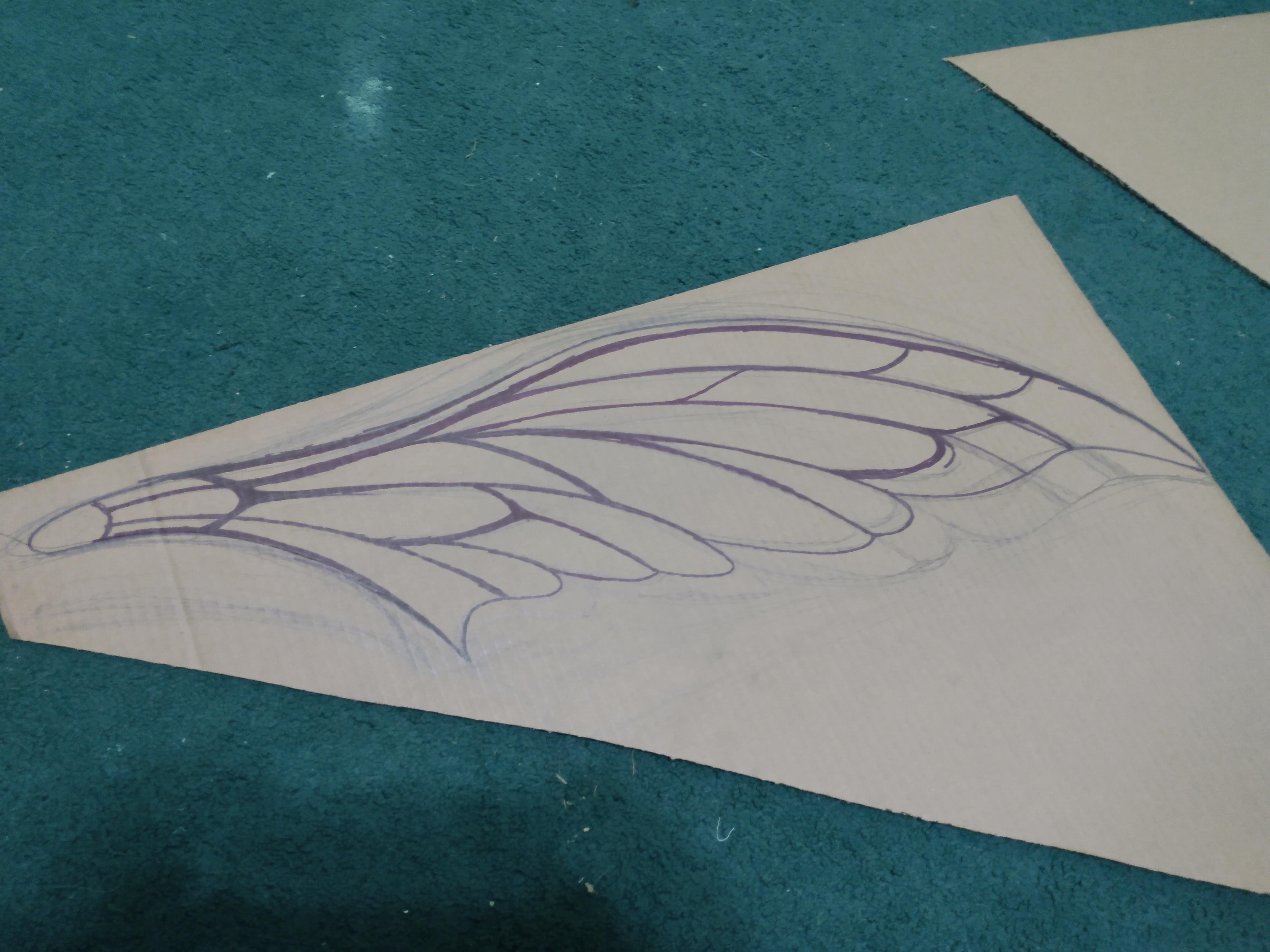
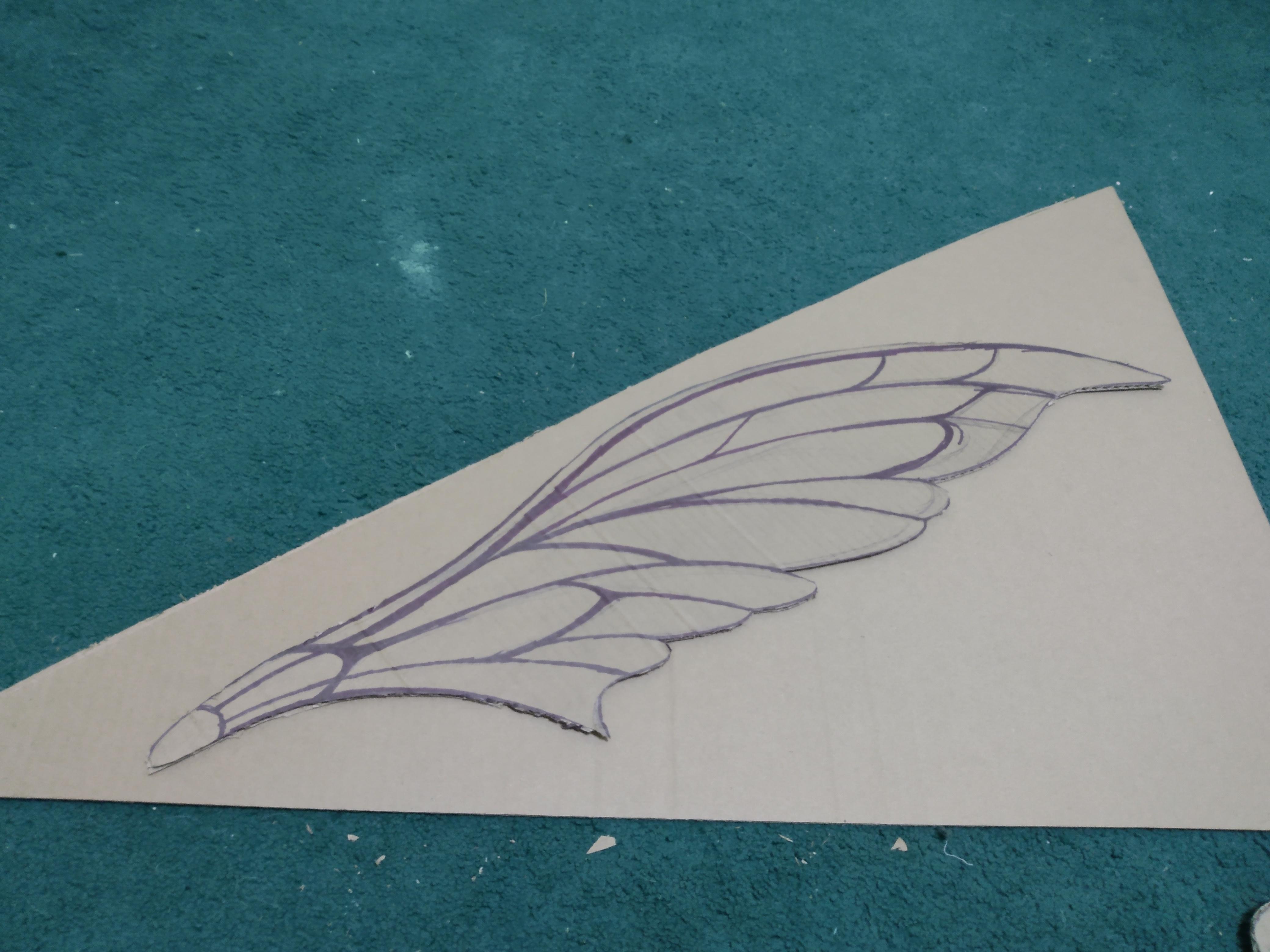
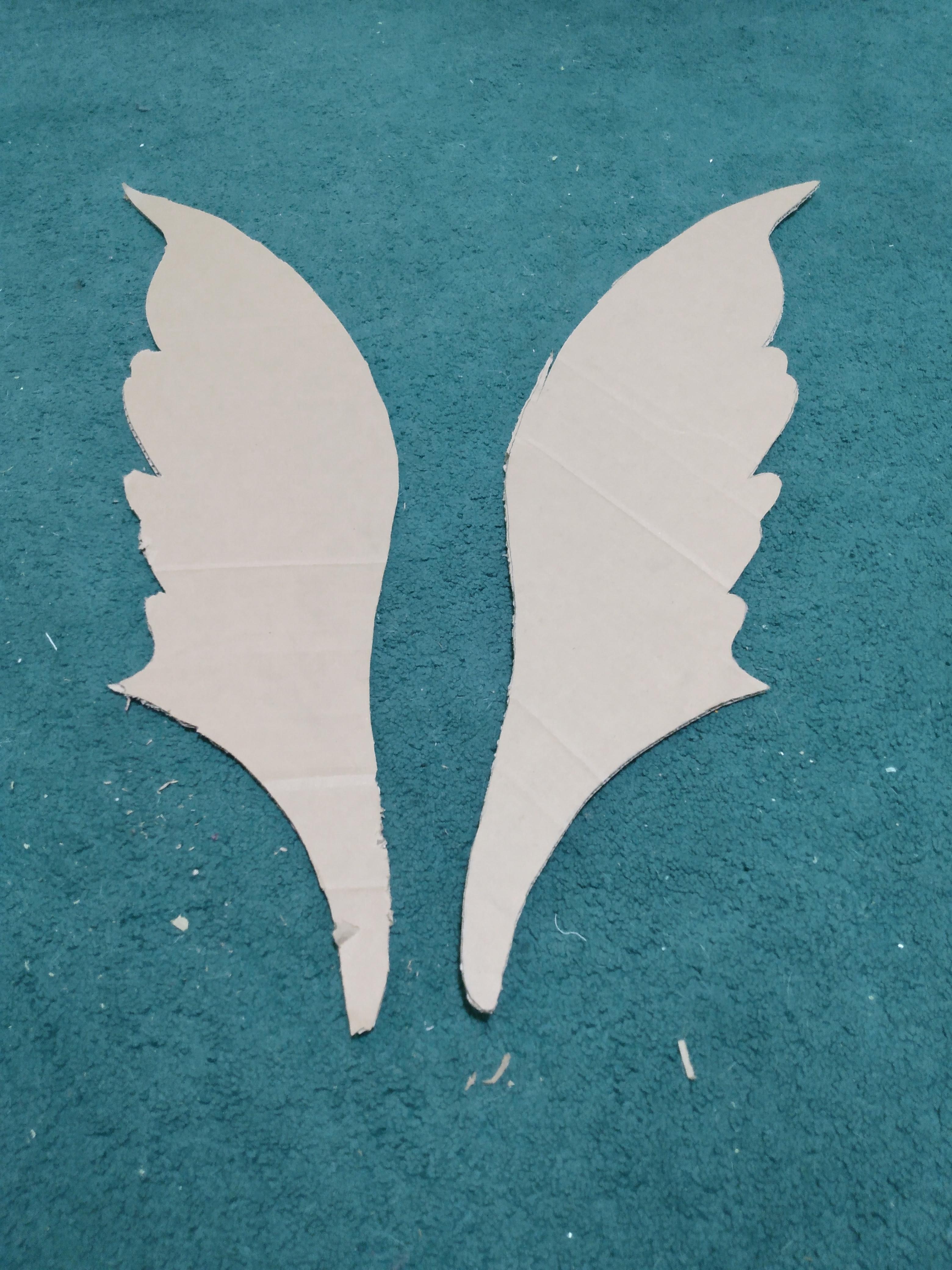
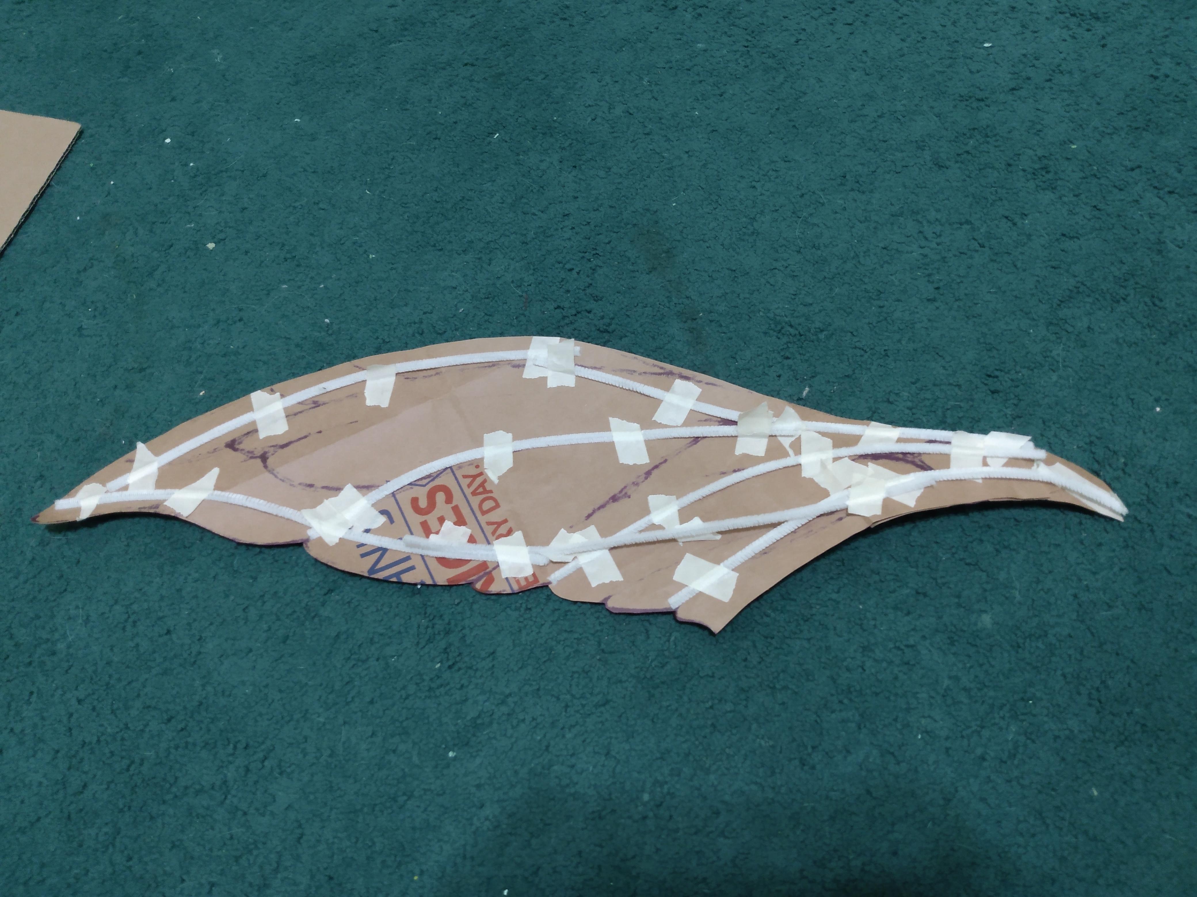
Honestly, these are optional. I do recommend doing this, though, to test your servos with the same size object and similar weight to the final result, to help you make any necessary adjustments during this part of the project. Obviously these won't become your actual wings, but before you make the wings you should be sure that the motors are functioning the way you want them to and can handle weight.
Make sure that the cardboard or paper bags are large enough for your wings. You can use it as a "stencil" for tracing the contour of the actual wings in part 2 (for an easier and cleaner process), so the size of the model and the actual thing should be a 1:1 ratio. Also, remember, when you're designing wings, respect copyright. Don't copy the wings you see that are drawn or created by someone else. You can mix and match these designs to create your own, or simply refer to nature, but the legal trouble isn't worth it.
If you're using cardboard, lay down the pieces on the floor, and sketch out one of your wing shapes in pencil. Make sure the sizing is right before taking a sharpie or otherwise thick dark pen or marker, and tracing the outer and inner contours of the wing frame. Cut the cardboard wings out, but only around the outline. On the other half of the cardboard, lay down the newly cut wing and trace along the outside to create your second wing.
If you're using paper bags, cut them so they open up completely. Follow the same steps as for the cardboard wings, but after cutting out both, lay them down in opposite directions (as if they were being worn), and using your tape and popsicle sticks, tape the sticks to the wings the same way you would a metal wire frame. You can also use hot glue for this part if you think that tape won't be strong enough.
I used cardboard for this project, but I did provide a picture of a prototype wing that was made with a paper grocery bag, tape, and pipe cleaners, though it ended up floppy so I don't recommend using pipe cleaners. You may need to reinforce the bags or cardboard with some extra layers of material, but be careful where you place the weight or the wings will be too heavy in the wrong places.
Attach Wings to Motors
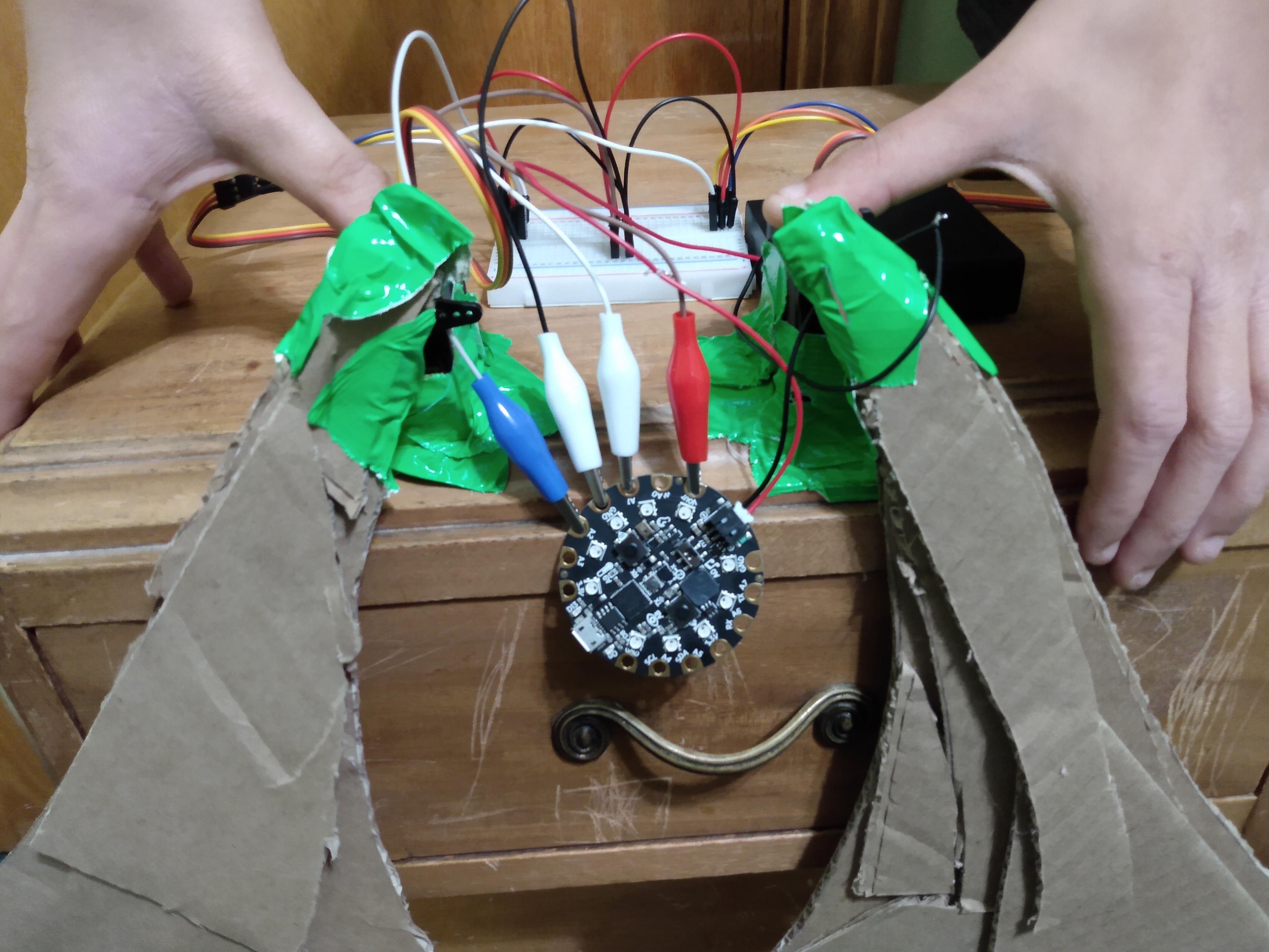
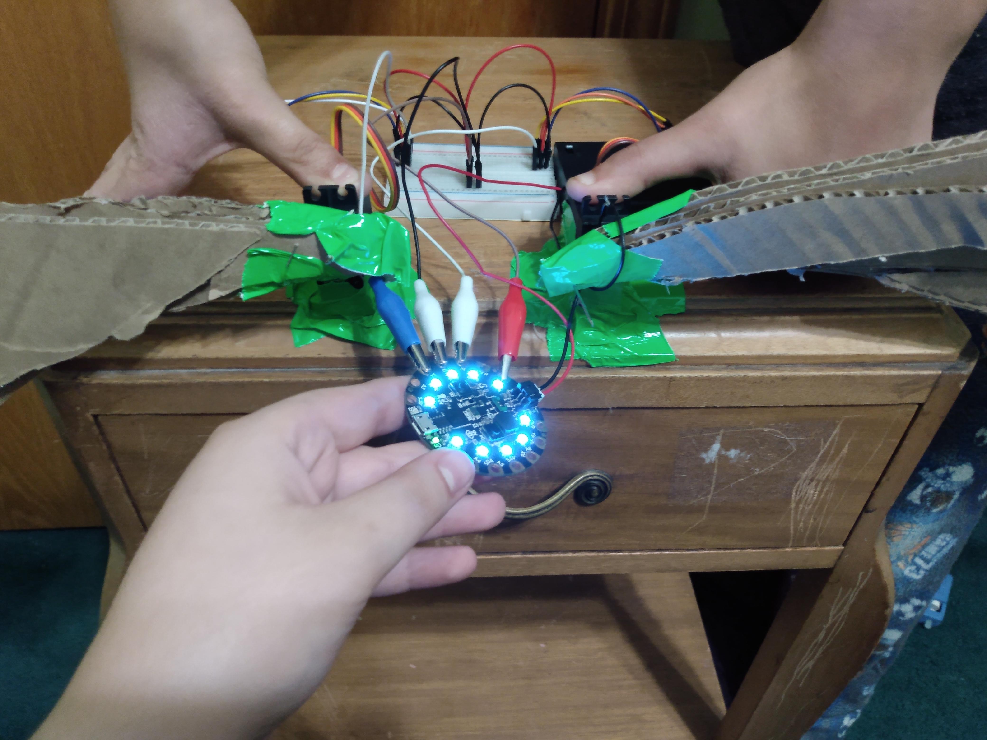
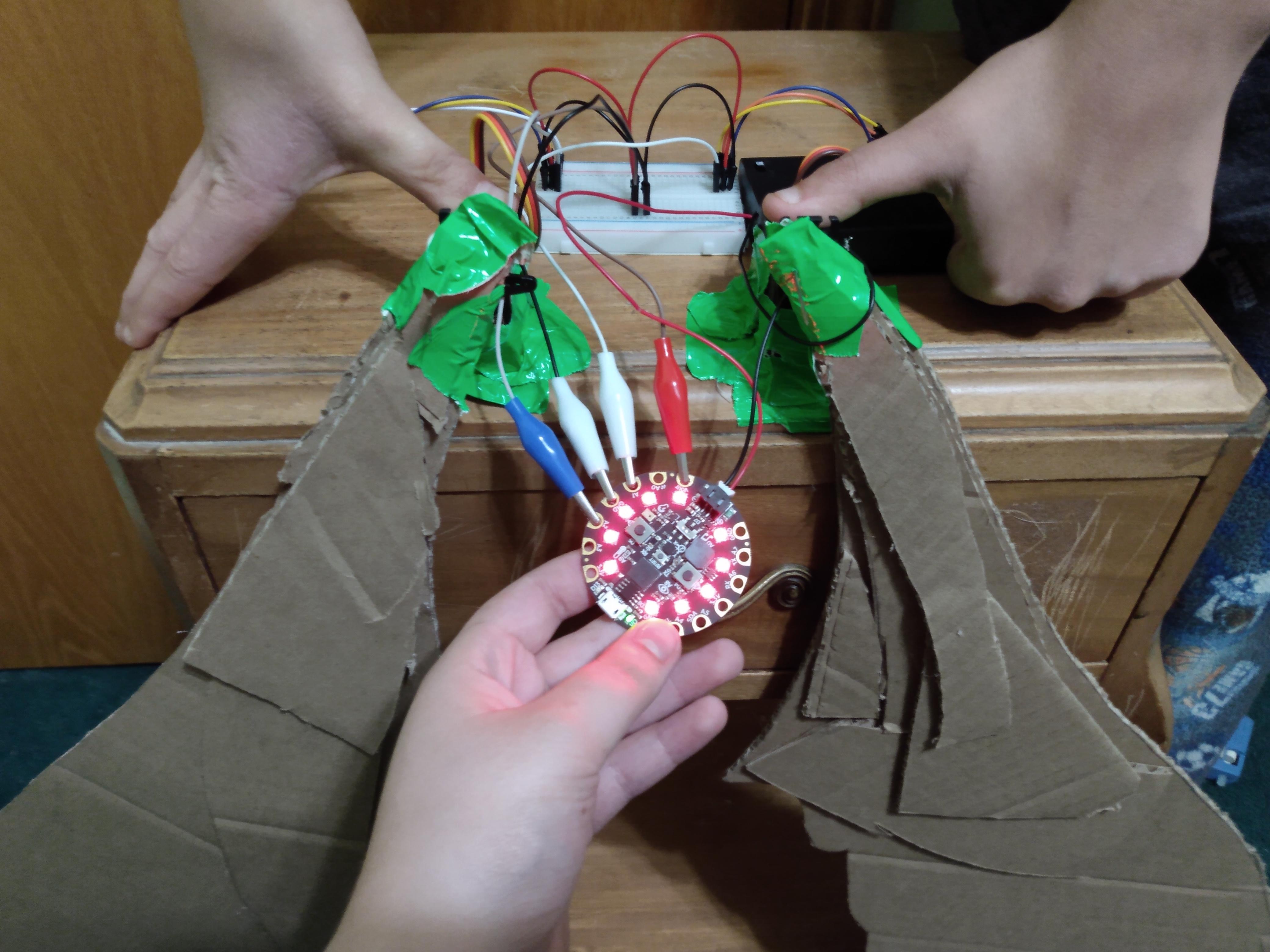
Put your servo motors at the edge of a desk or table with plenty of space in either direction, and secure them down. I used duct tape at the edge of a nightstand and some help from my brother, but you can use whatever works for you.
Attach the wings to the servos. Make sure you remember if the servos were in the "down" or "up" position when they were turned off, and attach the wings accordingly. I used a mix of duct tape and heavy duty pins.
Plug in your CPX to the desired power source, and test the wings out. If all goes well, when you tilt the CPX upwards, the wings should follow, and the opposite for downwards. Test it out for a few minutes, making any adjustments you need to.
Remember that these are prototype wings and may be bulkier or heavier than the final project, and use them as a guide for mistakes. For example, on my right wing, I added too much weight towards the middle of the wing rather than the end, so it pulled at the motor and caused it to be a little more aggressive than planned. Take note of these mistakes so you can fix them, such as making the wings lighter and focusing the weight where the wings meet the servos.
Final Adjustments
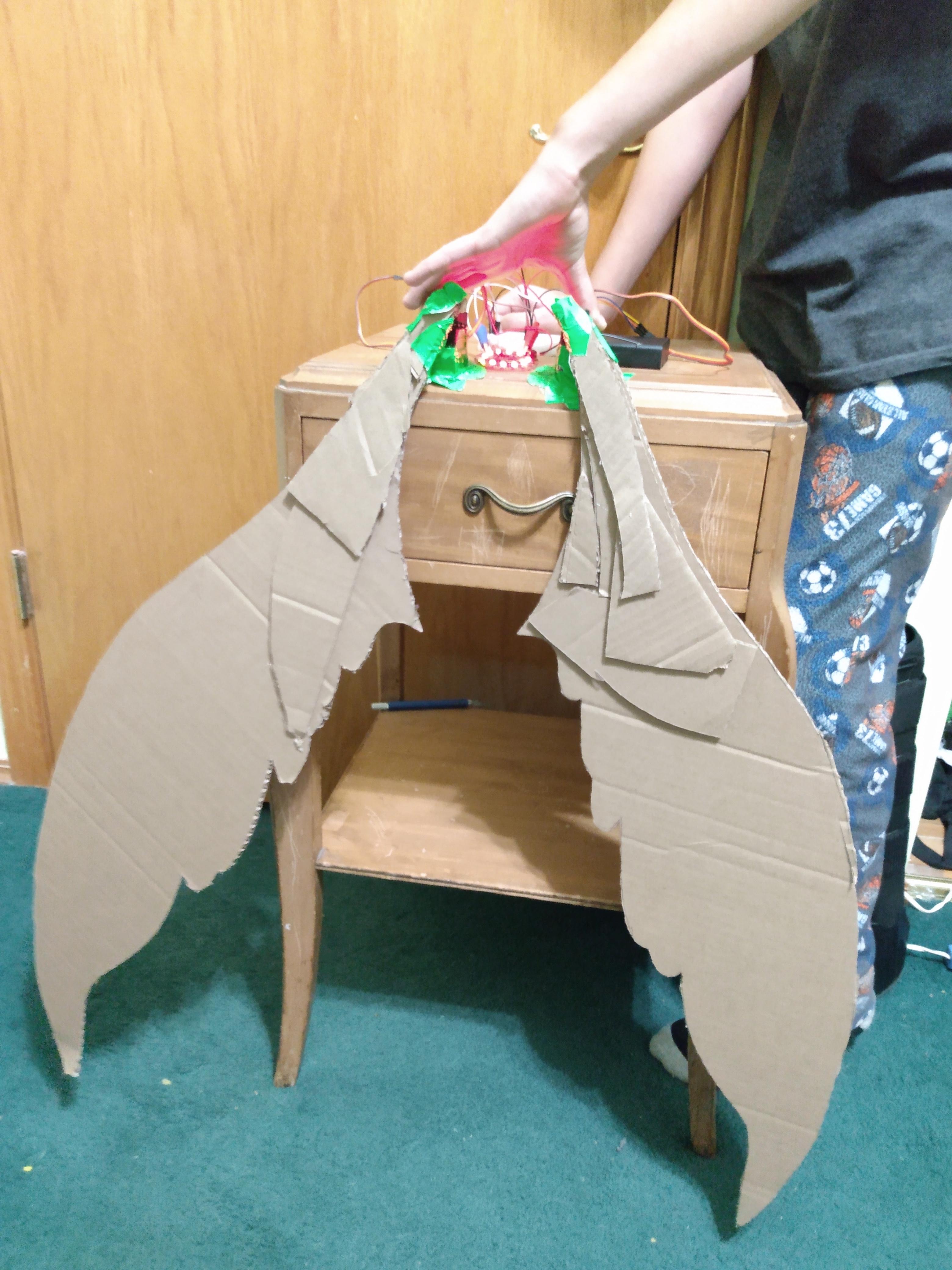
Make any tweaks to the wiring or coding you need or want to now. Once you're happy with how the servos react to the movement of the CPX, you can move on to part two of this project, which will cover the conversion of this project to a wearable pair of wings, linked here!