Mood Lamp
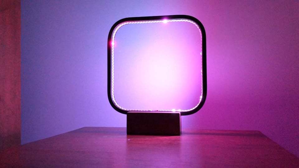
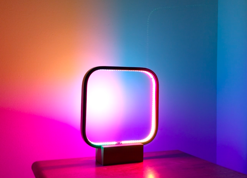
In this Instructable I show how to create a simple color changing mood lamp with different effects! You can change the color and effect on demand using an Arduino.
For this project here is a list of materials I used
- Old lamp that has an outside frame (I bought mine for 15$ at a general store)
- 5v LED strip (144 leds per meter)
- Arduino
- Wires
- Wire cutter
- Soldering iron and solder metal
- Wire connector for 3 wires
- 2 * 220 ohms resistors
- Button
- 10k Potentiometer
Modify the Original Lamp
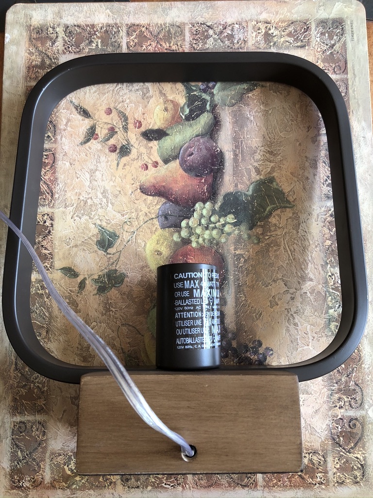
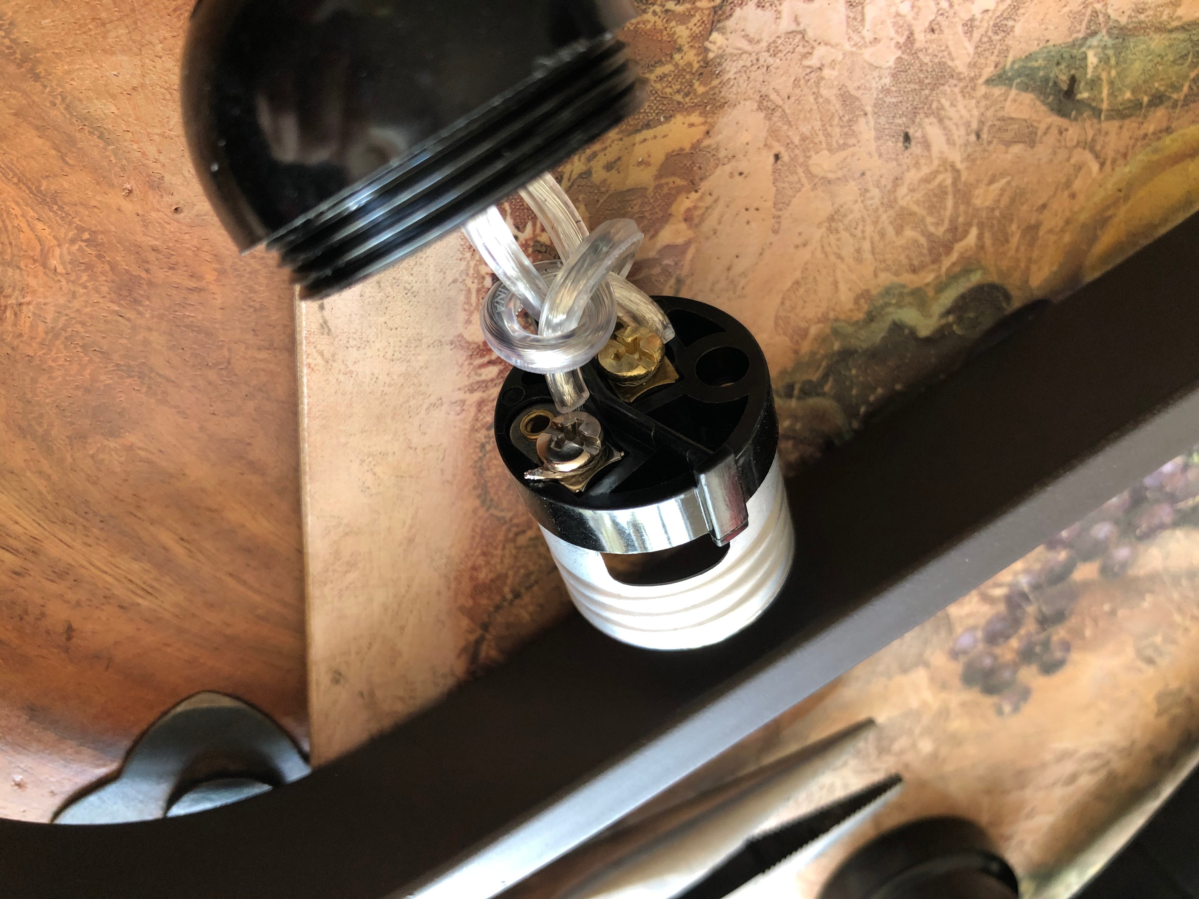
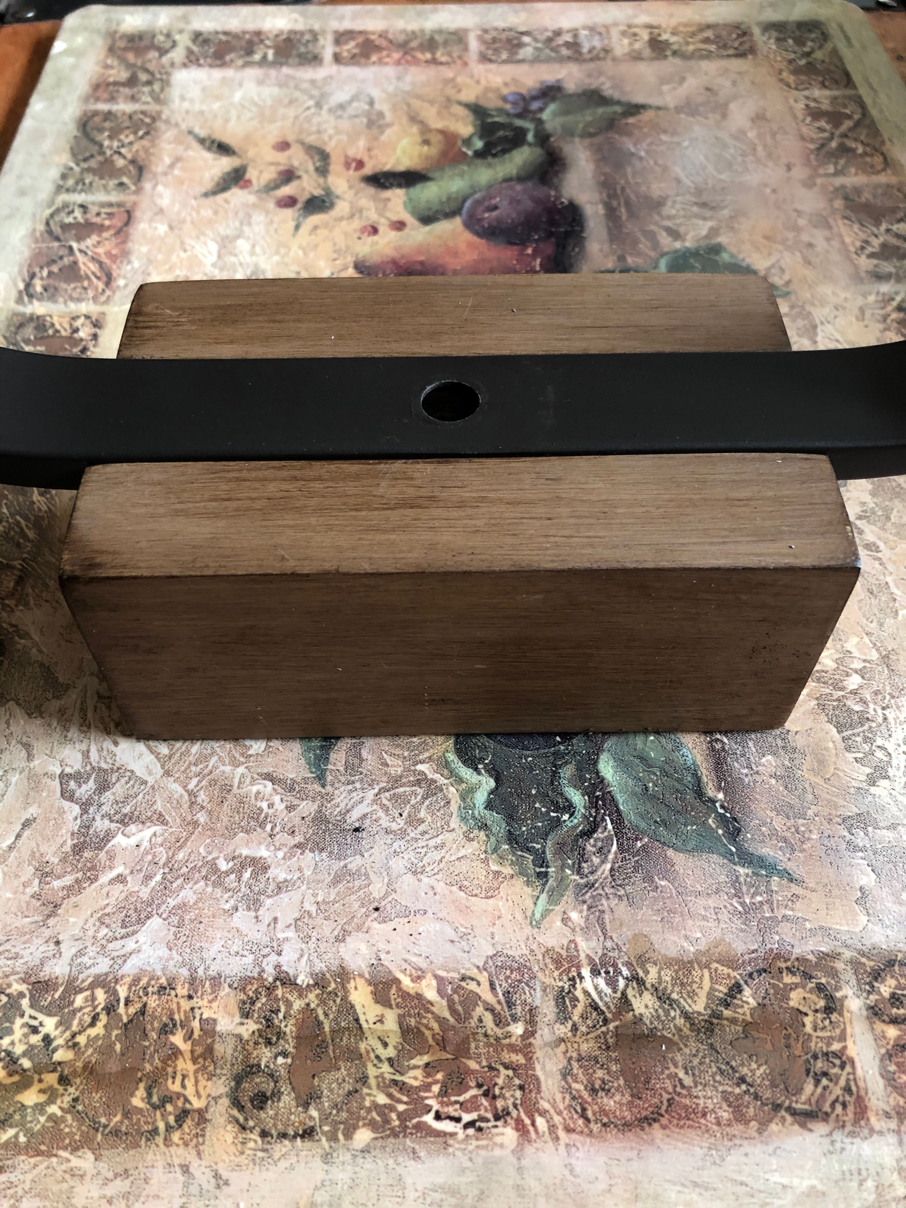

Depending on the lamp you have, remove any pieces in order to simply keep the outside frame. In my case, I removed the wiring and light bulb holder. All is left is the trendy frame.
Place the LED Strip
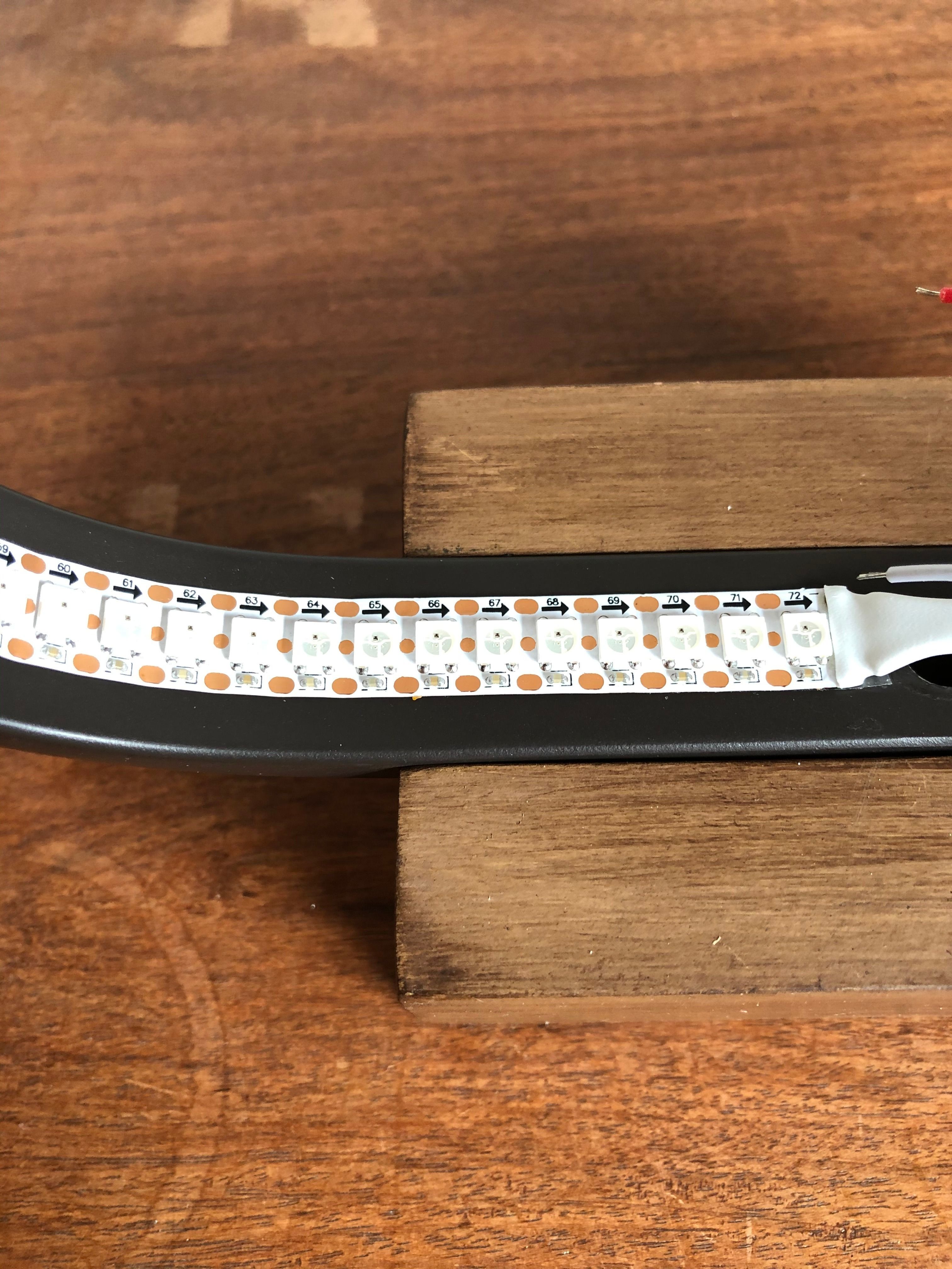
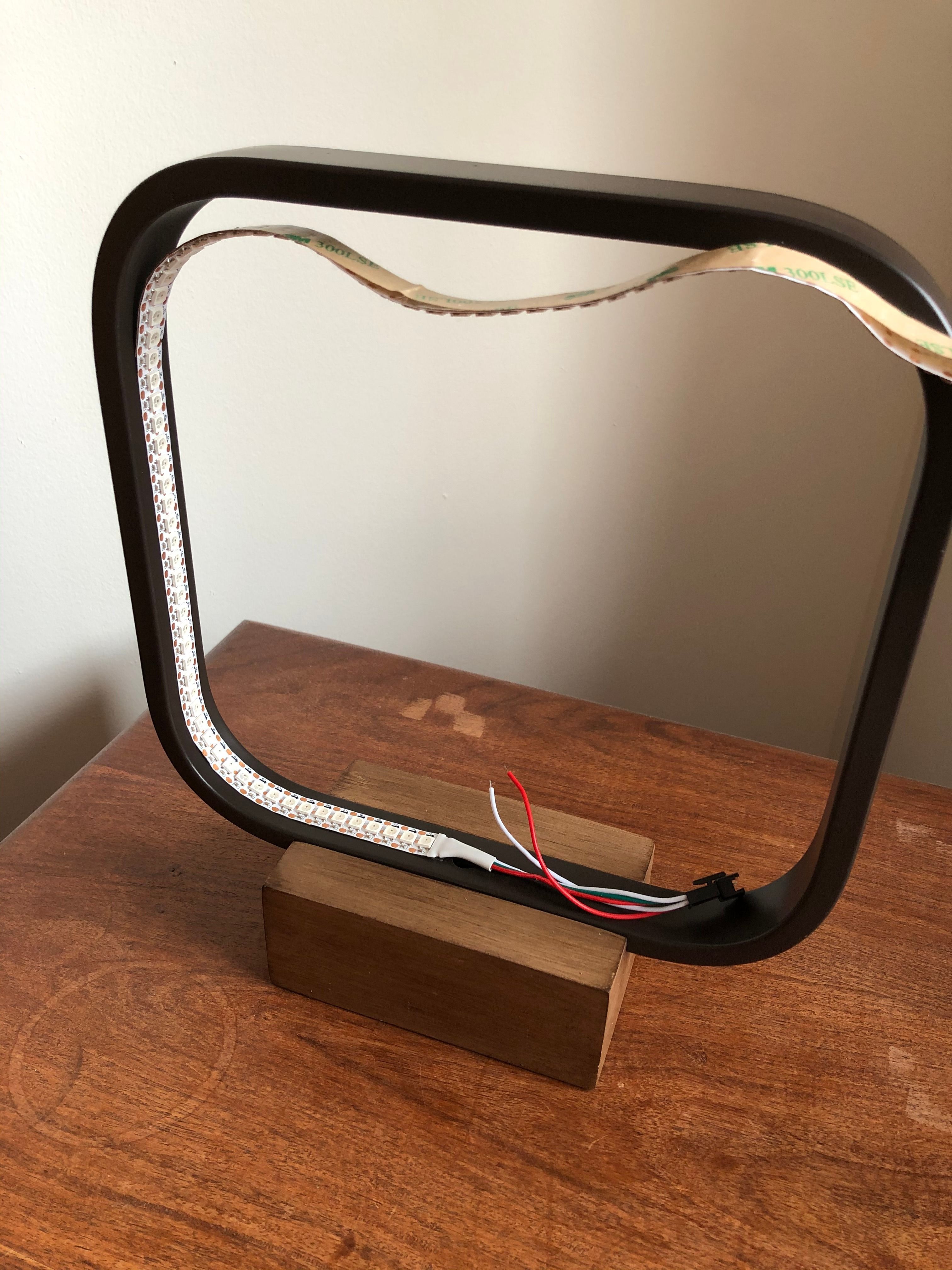
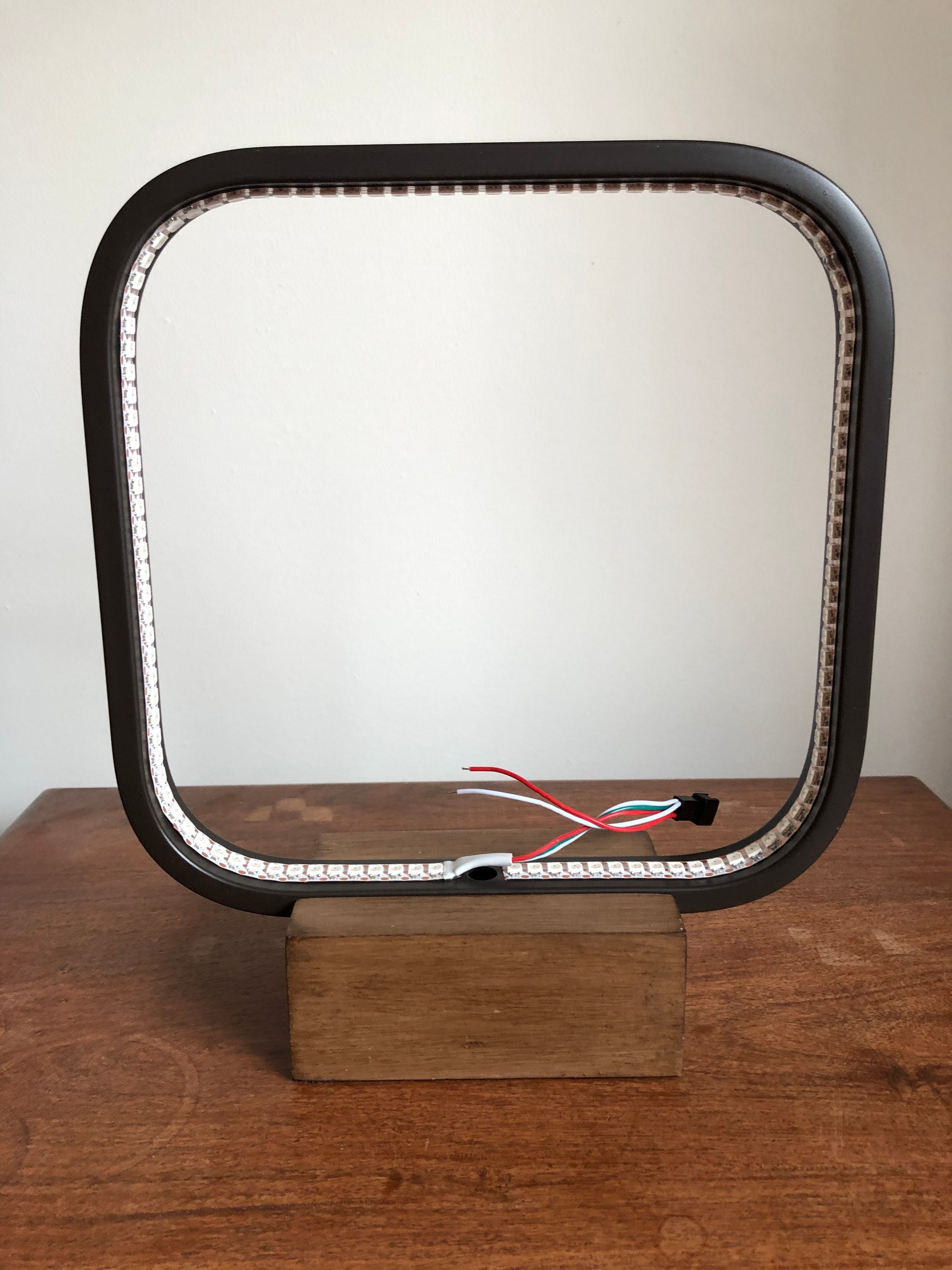
Place the strip and glue it all along the inside of the frame. When you covered the whole frame, cut the strip.
Connections
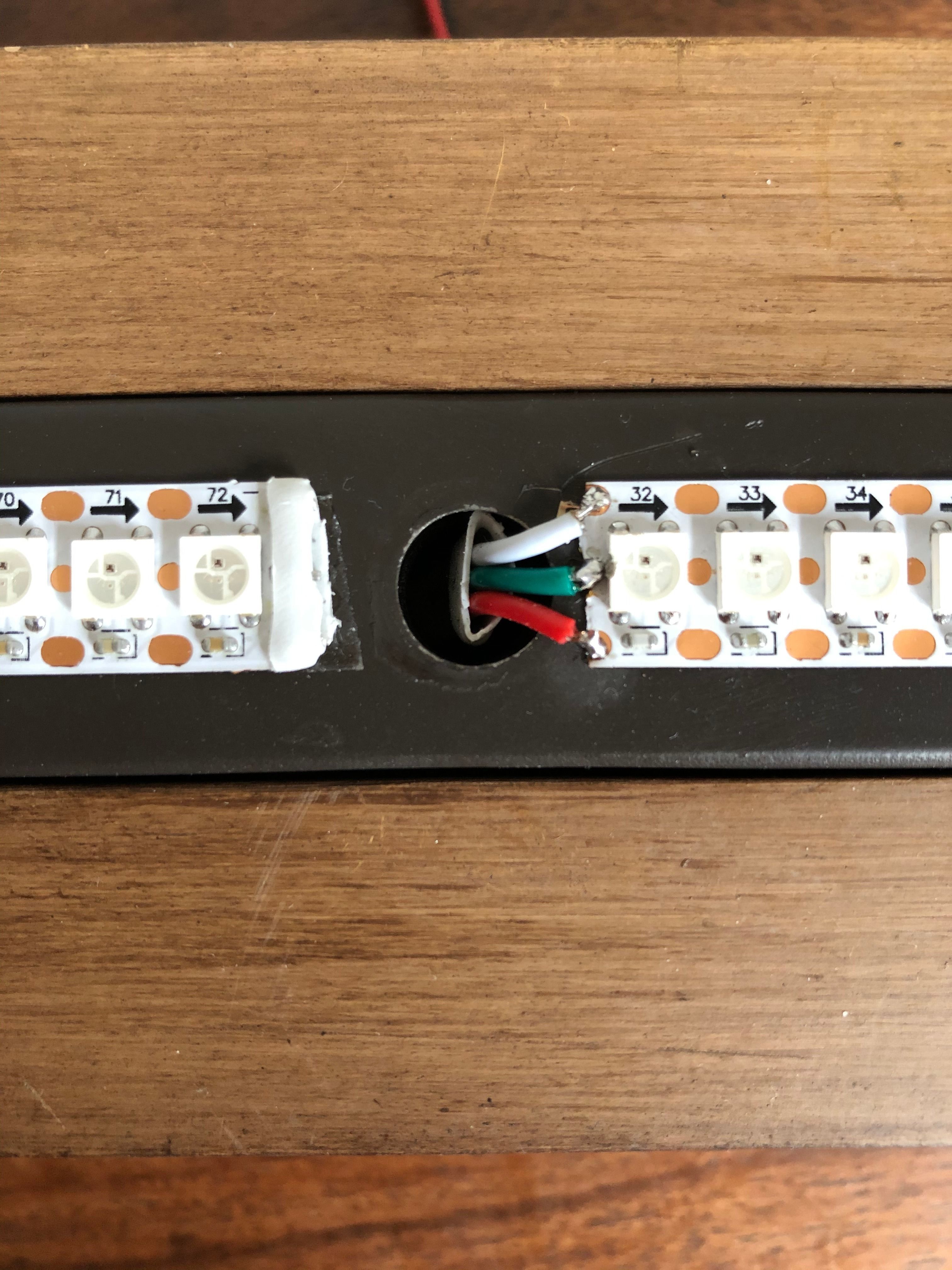
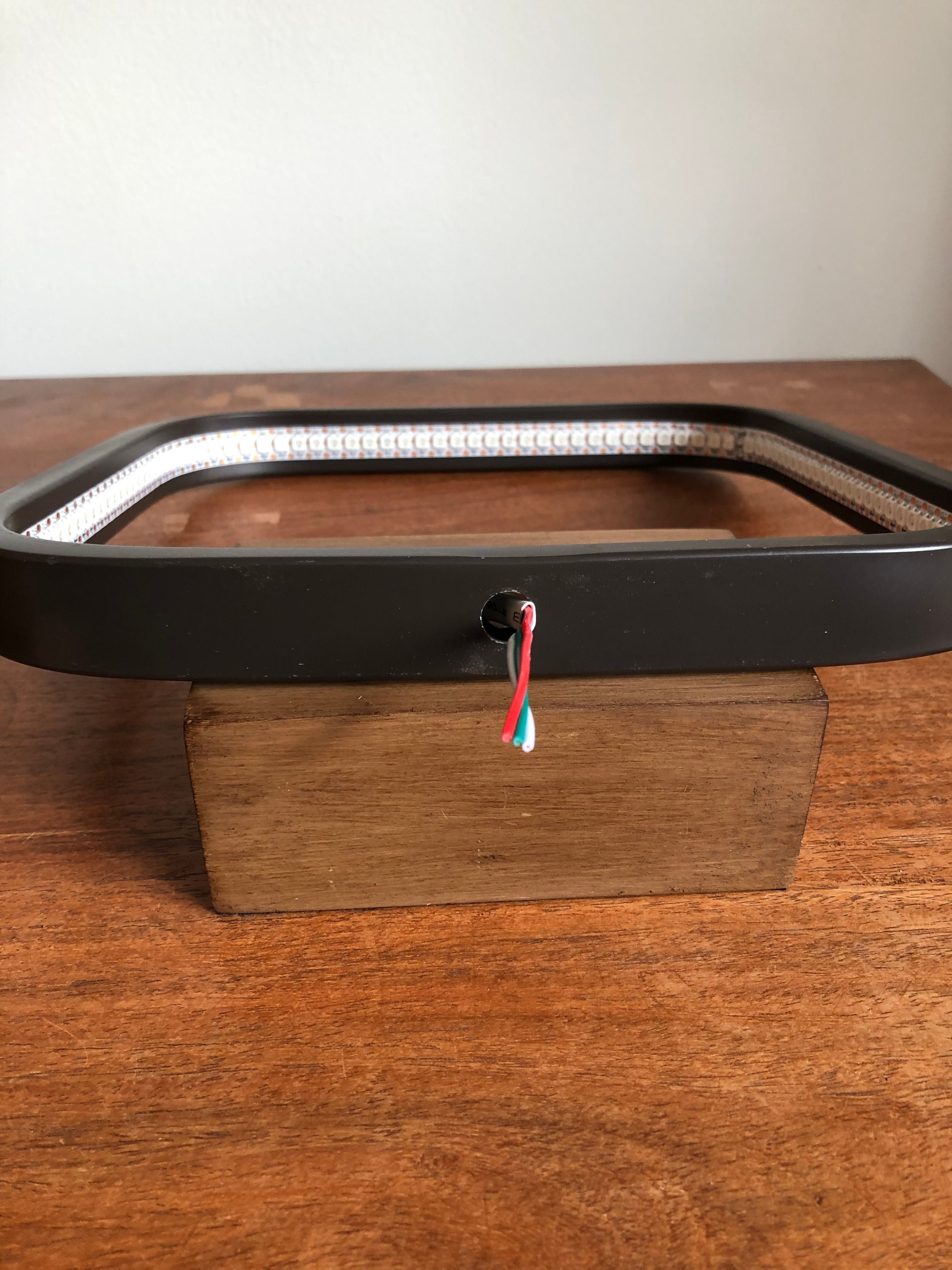
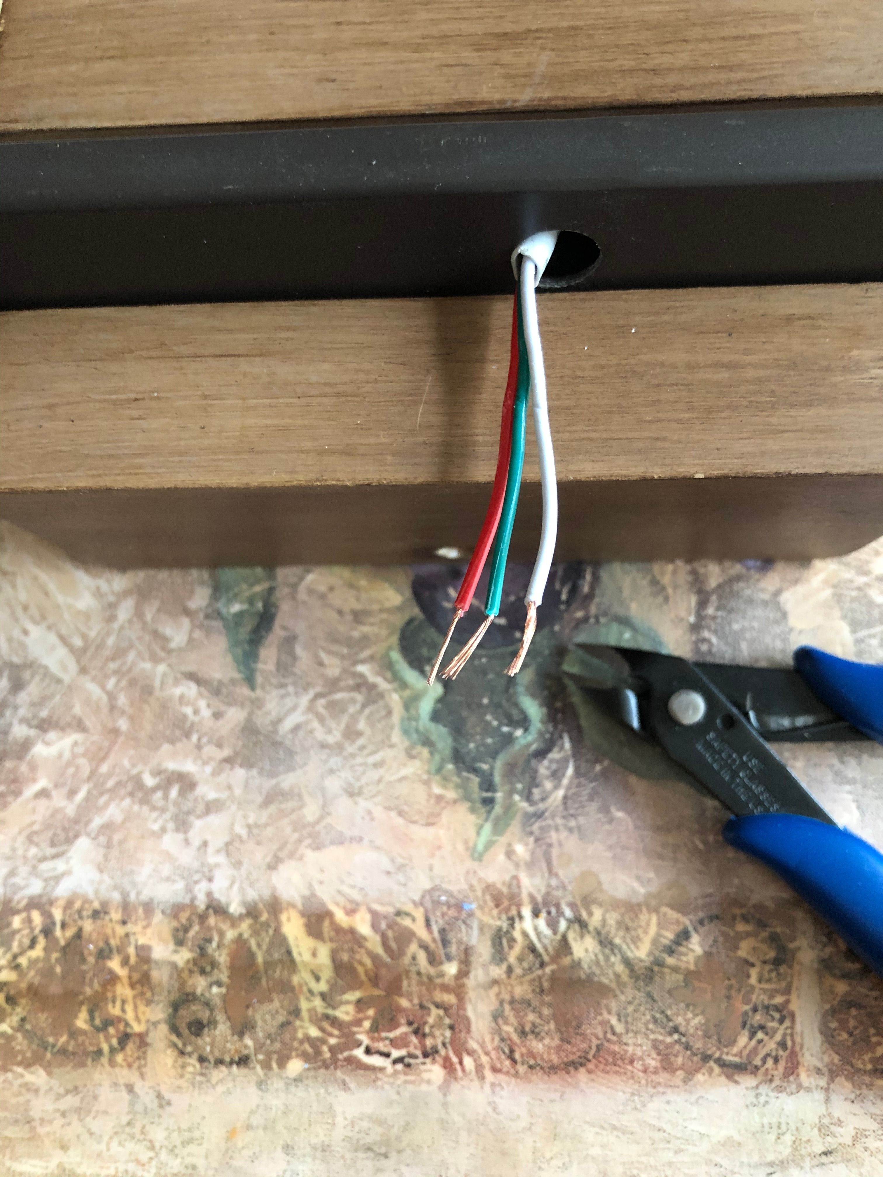
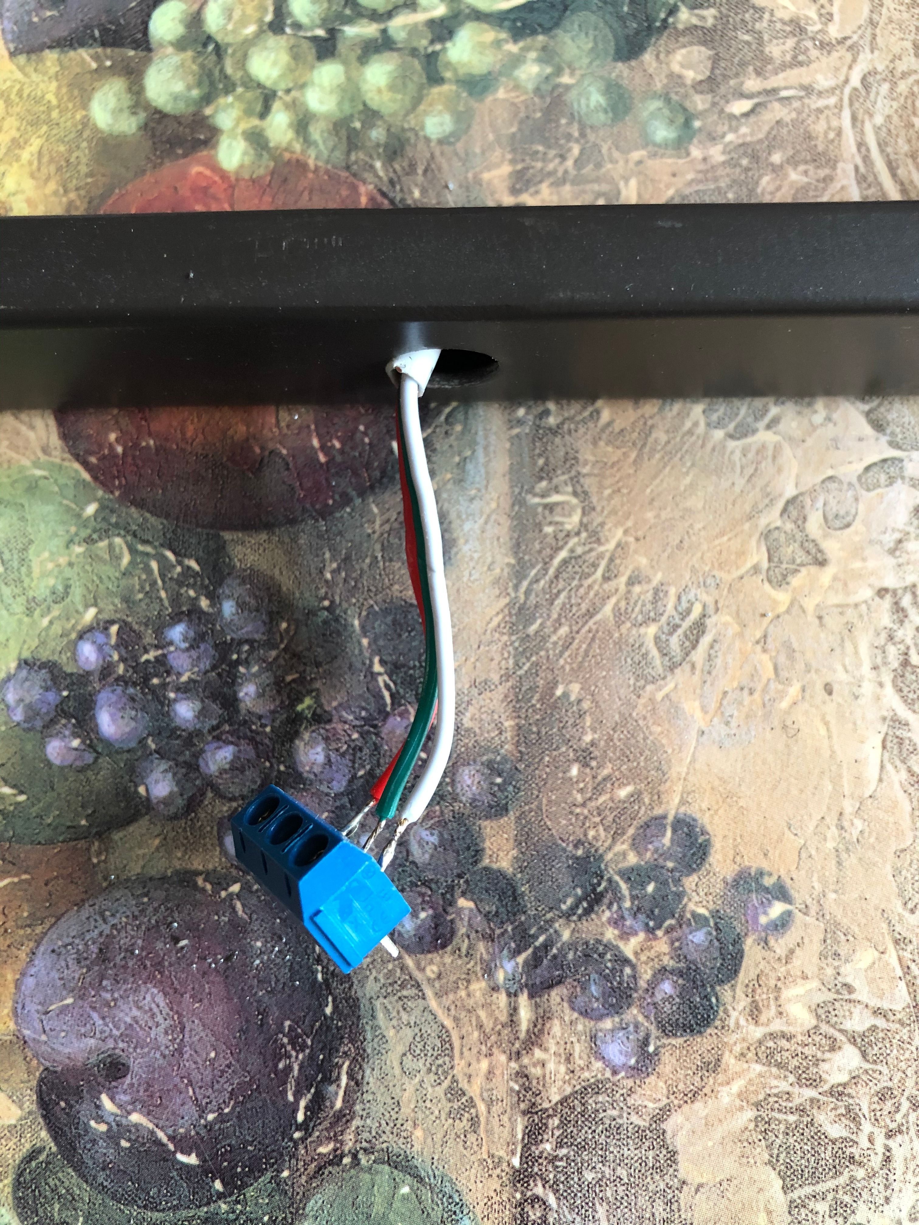
If you’re using a new strip chances are connections are already wired!
Otherwise, you need to connect three wires to the strip using a soldering iron and soldering metal. Depending on your strip, the connections might differ. Arrows on the strip indicate the direction. In my case, the top connection (near the arrows) is ground, the middle is for accessing the LEDs, and the last is for the input source. I used green for data input, red for the voltage source and white for ground.
Once your connections are made, pass the wires in the hole of the lamp (originally used for the bulb). Add a connector for three wires to make it easier to connect with the arduino.
Arduino Connections
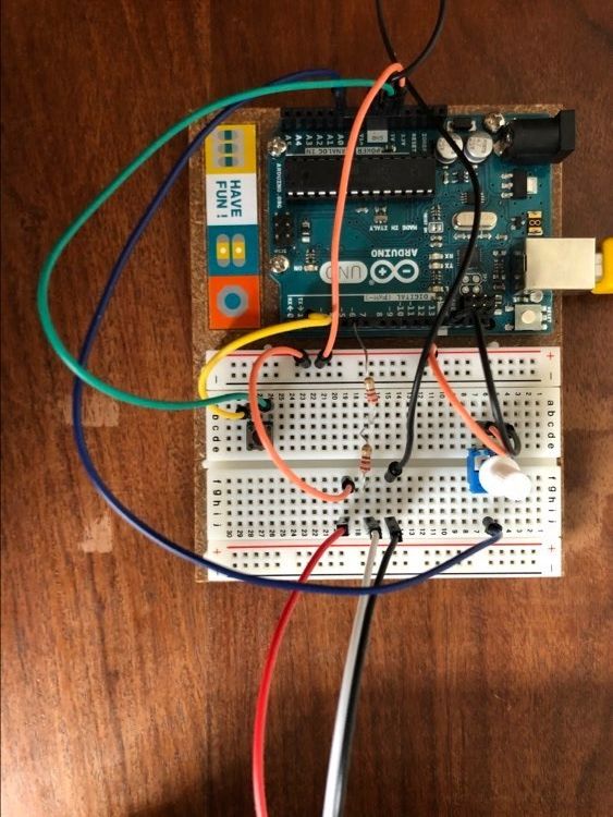
Now to add some light, we need to connect the strip to the arduino. I used a breadboard to make connections easier.
Add a connection between the ground pin of the arduino and the ground of the strip.
Add a connection between the 5v of the arduino and the input source of the strip.
Finally, add a connection between pin 6 and the data input of the strip.
It is suggested to add two 220 ohms for a total of 440 ohms between pin 6 and the data connection of the strip.
If you wish to control the colors, add a potentiometer connected to the A0 pin of the arduino.
Finally add a button connected to pin 2 of the arduino
Upload the Sketch

To control the LEDs, there’s a great Adafruit library. And there’s also plenty of sketch samples to guide you once you installed the library.
For the effects, I used and modified some from this website: https://www.tweaking4all.com/hardware/arduino/adr...
But you can easily make your own and get inspired from plenty of different sources!
You’ll probably need to modify the led count in the sketch
Downloads
Control the Colors and Effects
You can test the different effects by pressing the button and change the colors with the potentiometer!
Connect With a Battery
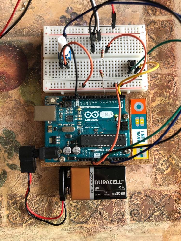
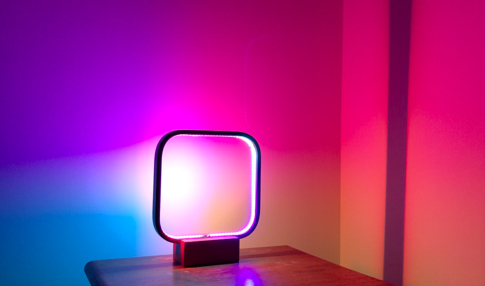
When you tested and you’re satisfied with your effects, connect the arduino with a battery and you’re done!