Monitor to TV Conversion
Hi all,
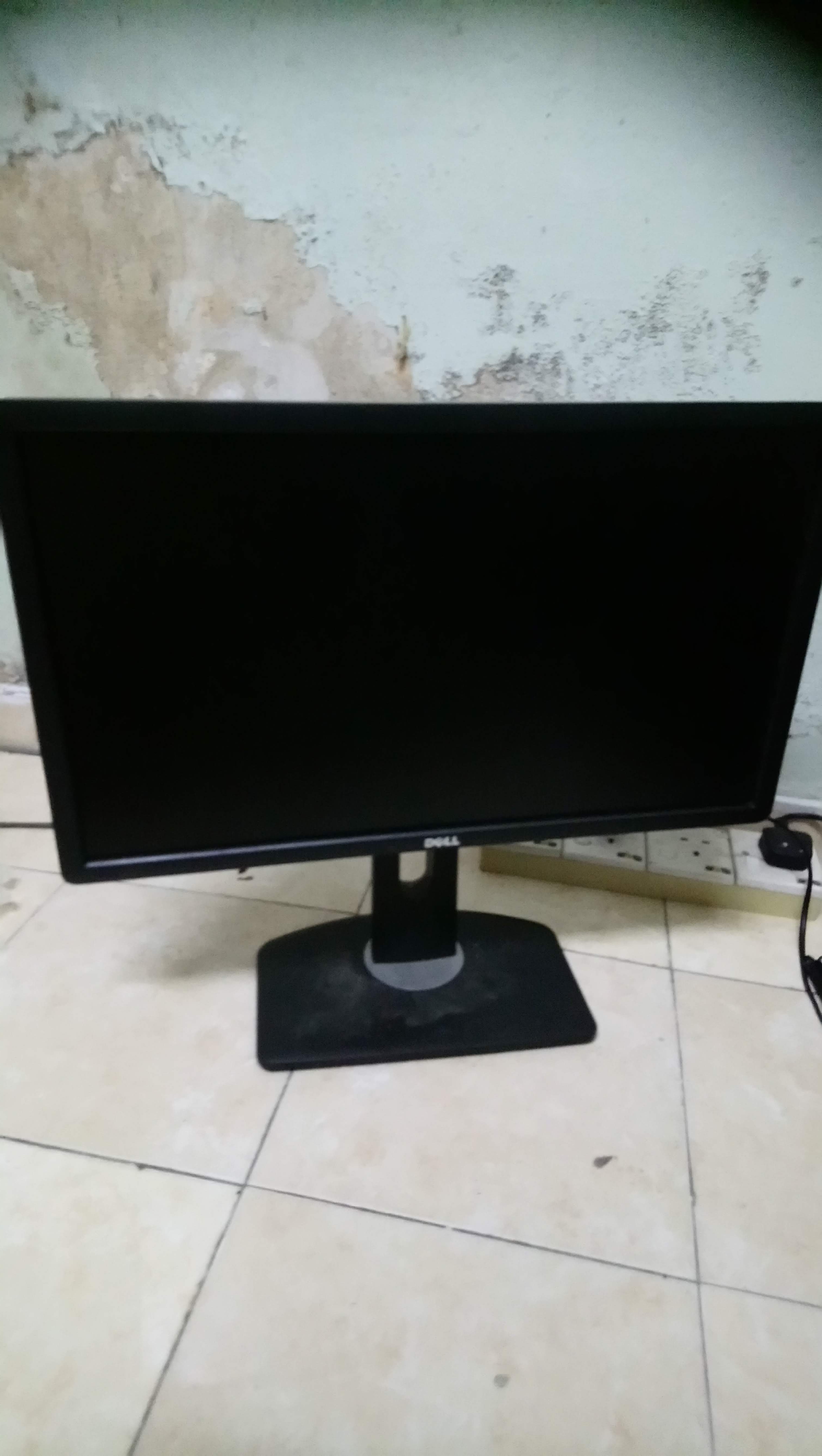
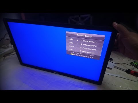
This Instructables is about converting computer LCD monitor rather laying around unused/damaged power board or controller. This instructables require a GOOD working LCD panel. Preferable larger (>20" screen)
Items Required
Item Required:
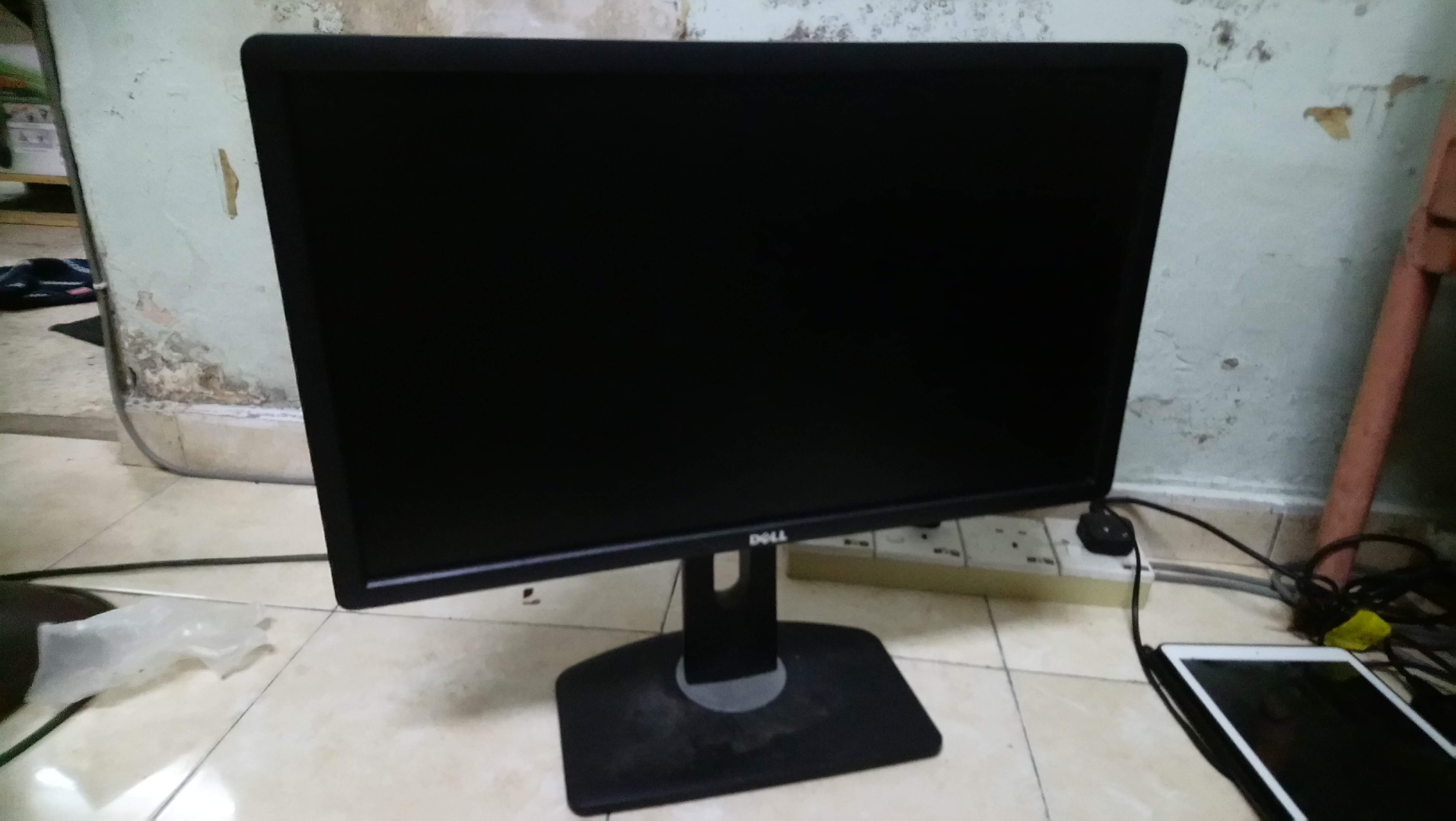
1. Spoiled LCD monitor with good panel (no crack/lines)
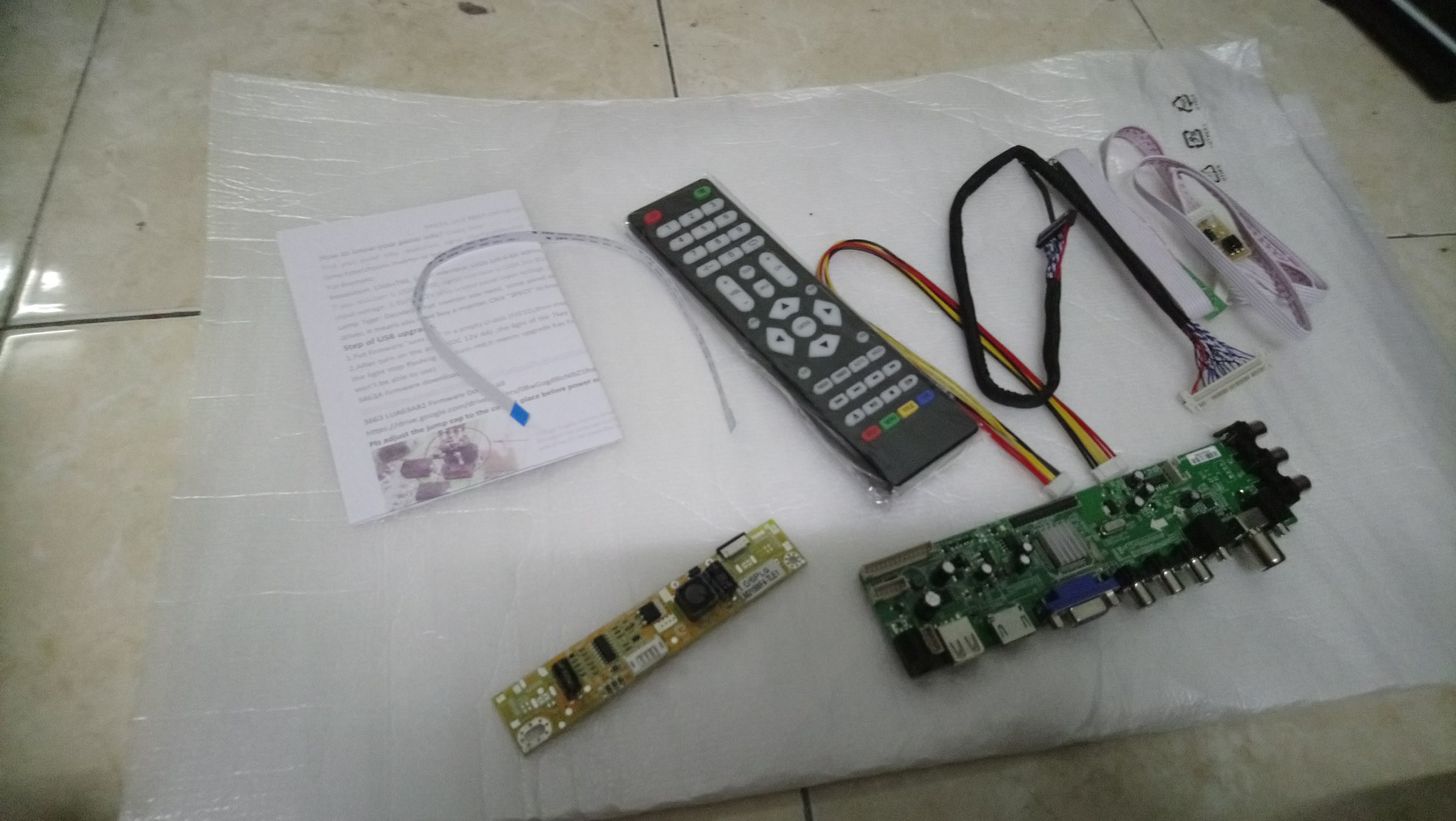
2. Universal LCD Kit-(Pls contact seller to confirm yr LCD panel type/model and they will suggest appropriate LVDS)
-Kit -with built in TV tuner is preferable.
-LED Driver (as LCD panel require LED backlighting- this is the driver)
-LVDS Cable(Low Voltage Differential Signal) ( A standard cable connecting panel to main-board) <common name for LCD screen technology industry
3. IEC Connector (AC in)
4. DC Power Supply (12V 4A)
5.PCB Standoff
6. Tools and power tool (Electric drill and Angle Grinder)
Dismentalling
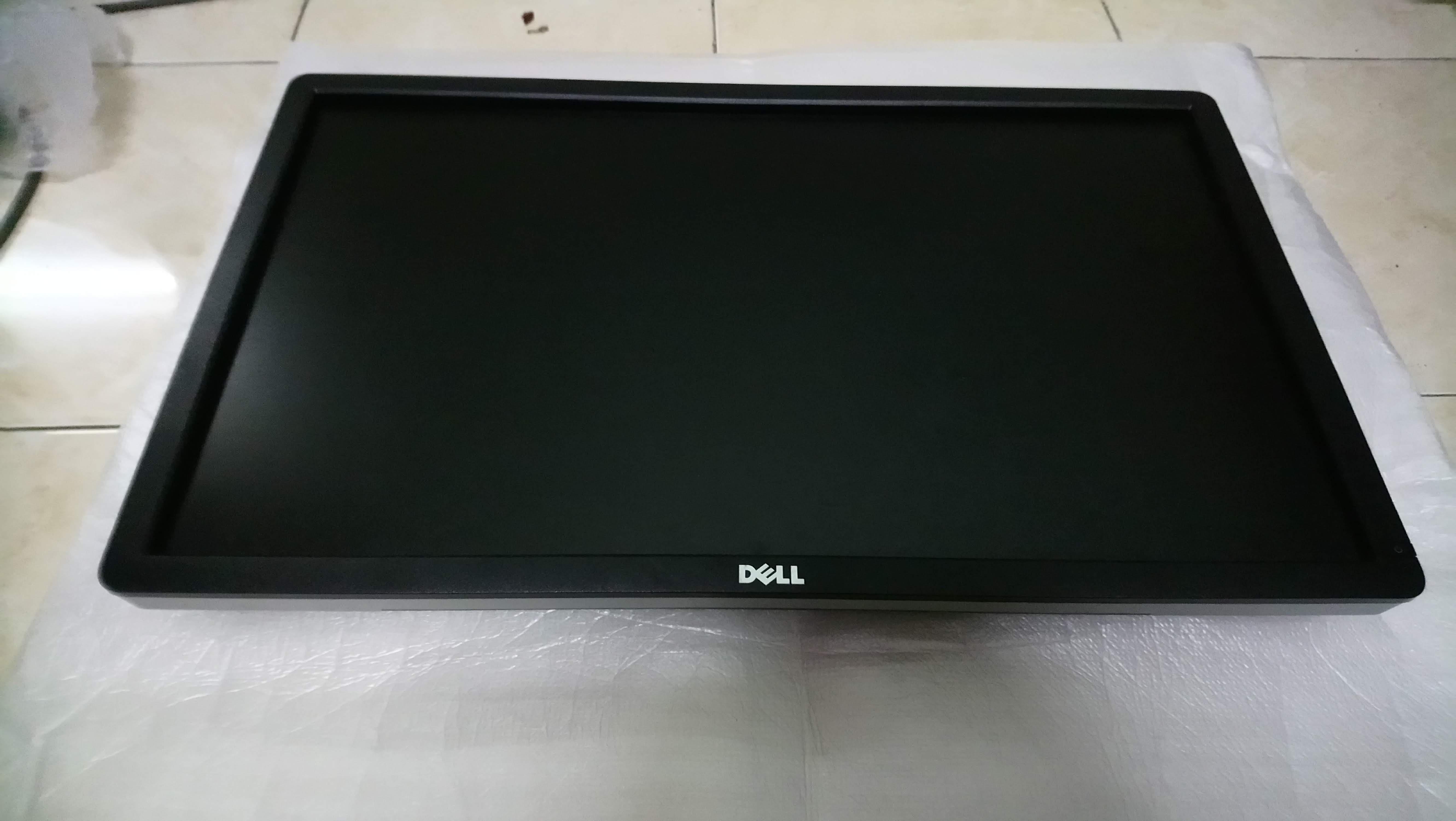
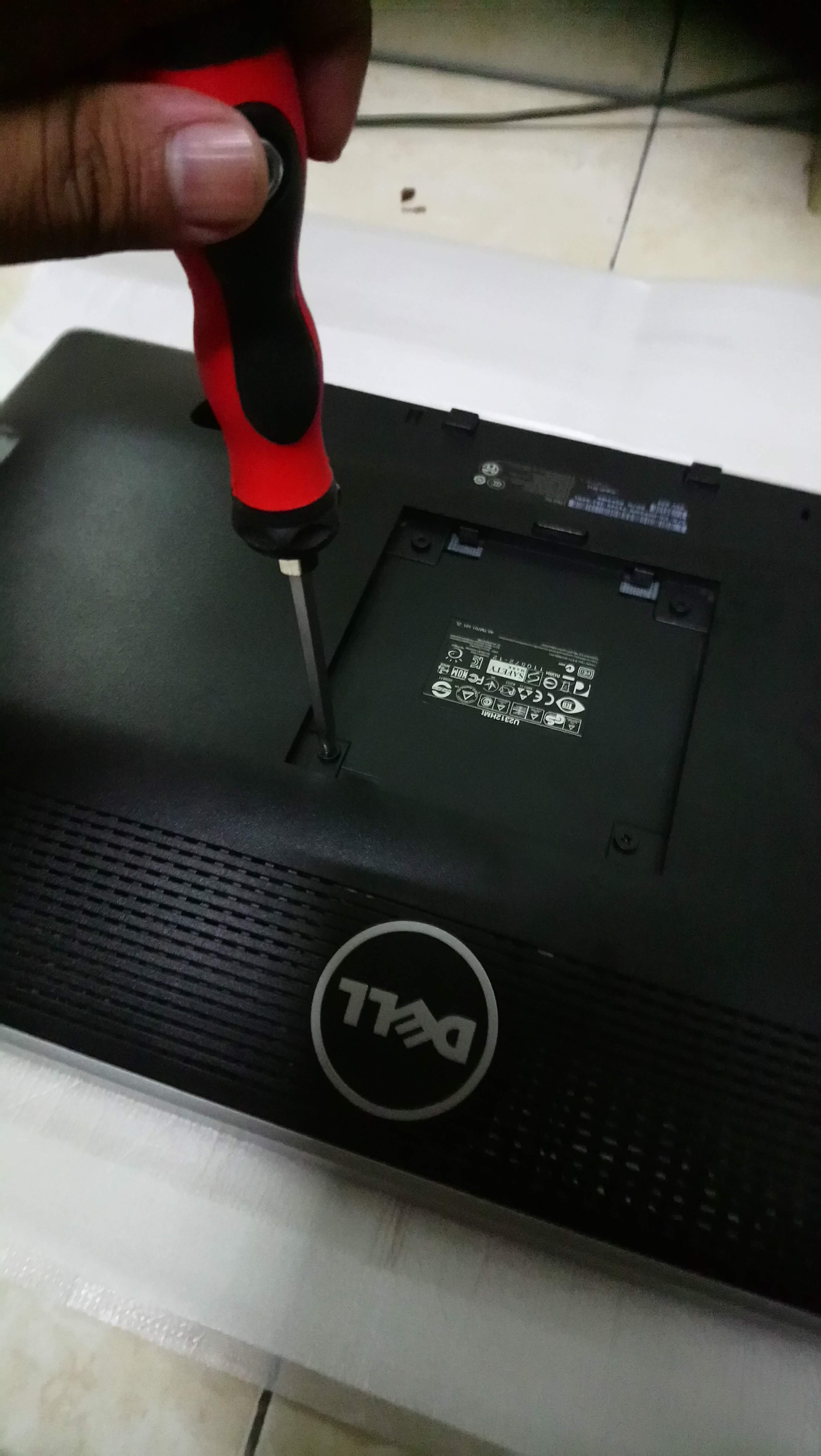
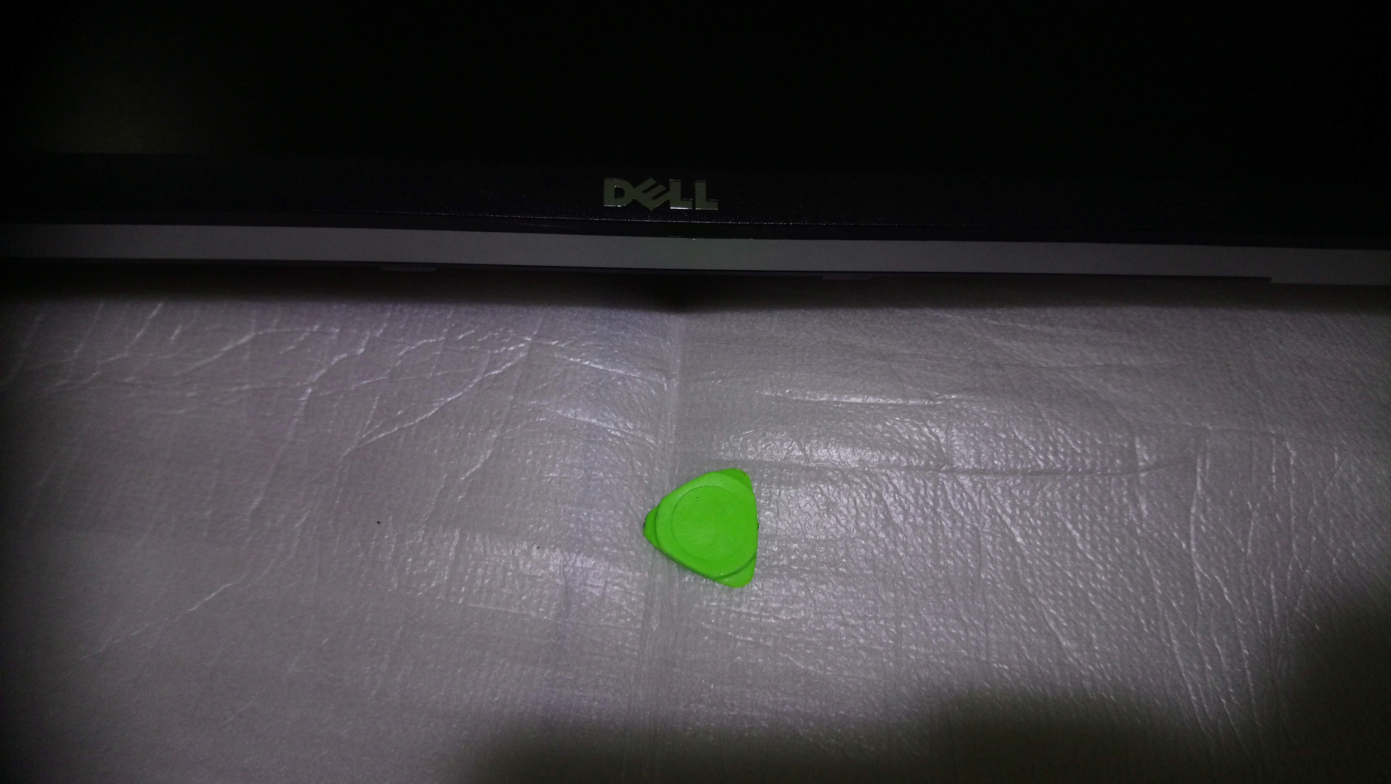
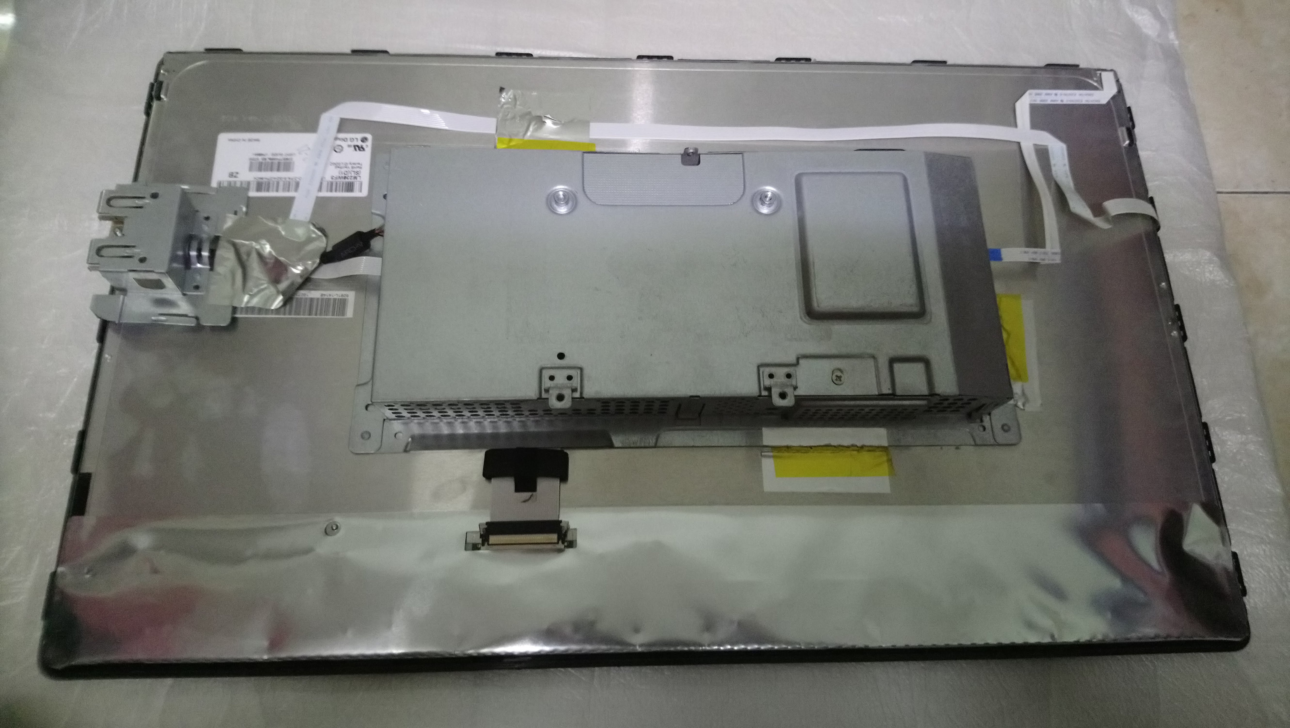
1 . Lying the monitor on flat soft/padded surface, in my case,PE bag (recycled from electronics packing material)
2. Remove the mounting screw.
3. Using prying tool, carefully pry the monitor bezel and frame.
4. Remove the cable and connected wire to LCD monitor.
5. Study and search the LCD panel specification at www.panelook.com for appropriate LVDS cable. Inquire the specification of your panel to Universal Board seller for advice and suggestion. There are many types of board specification
1-monitor only (VGA/DVI/HDMI)
2- Smart Android board
3- TV Board ( VGA/DVI/HDMI +TV tuner (ATV/DVB-C/DVT2) <-- I choose this as malaysia MYTV spec DVB-T2
Testing
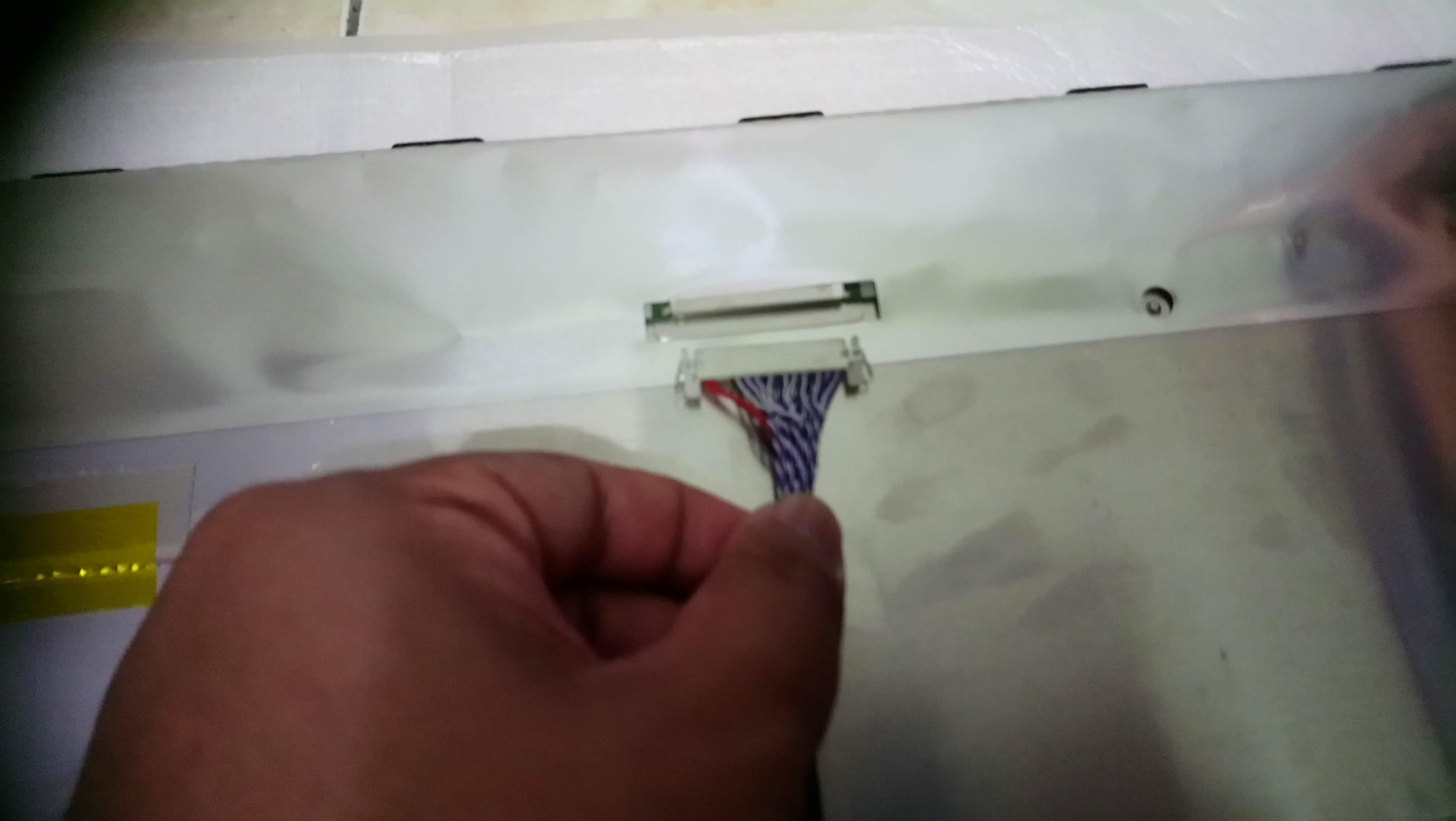
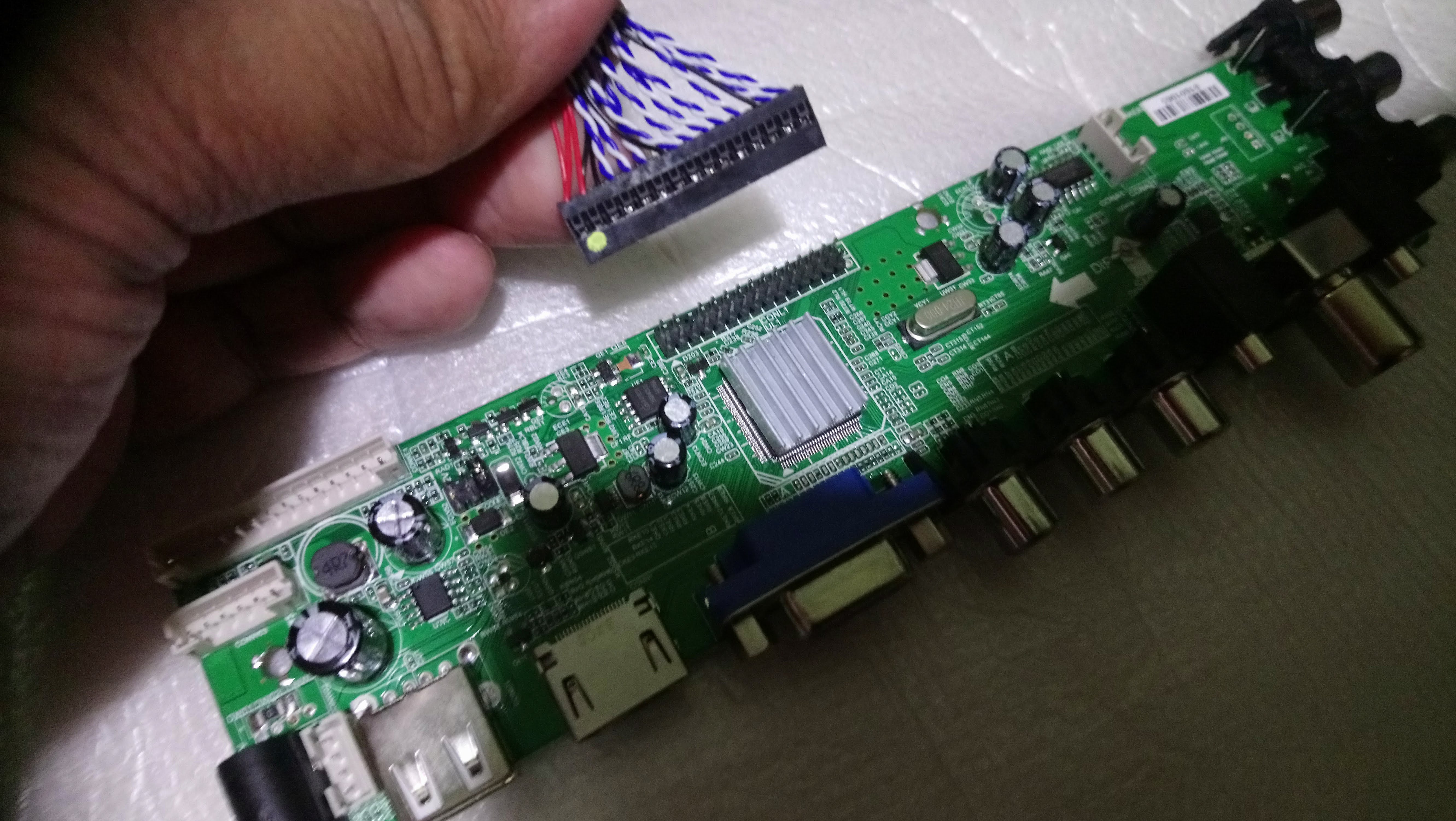
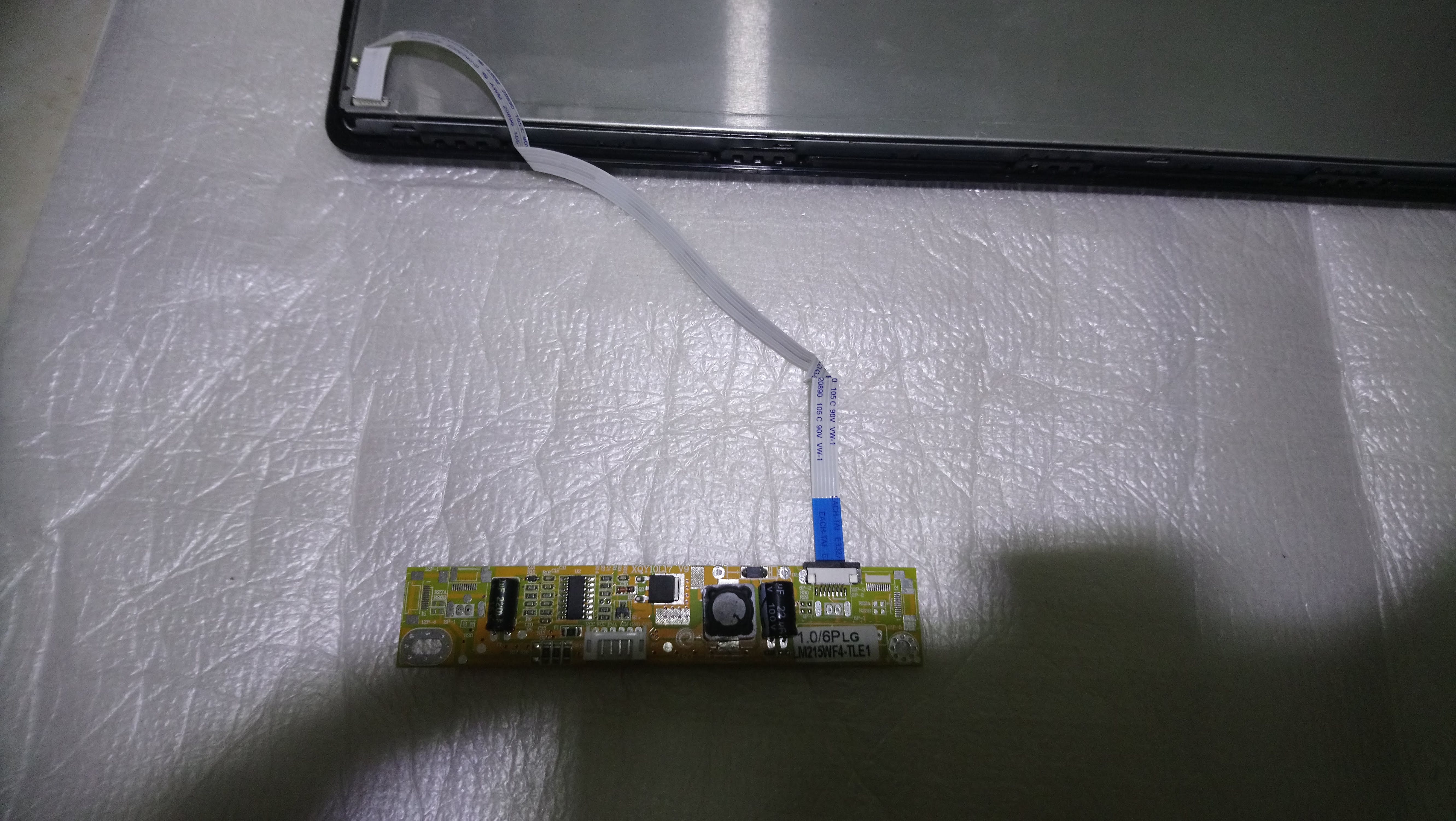
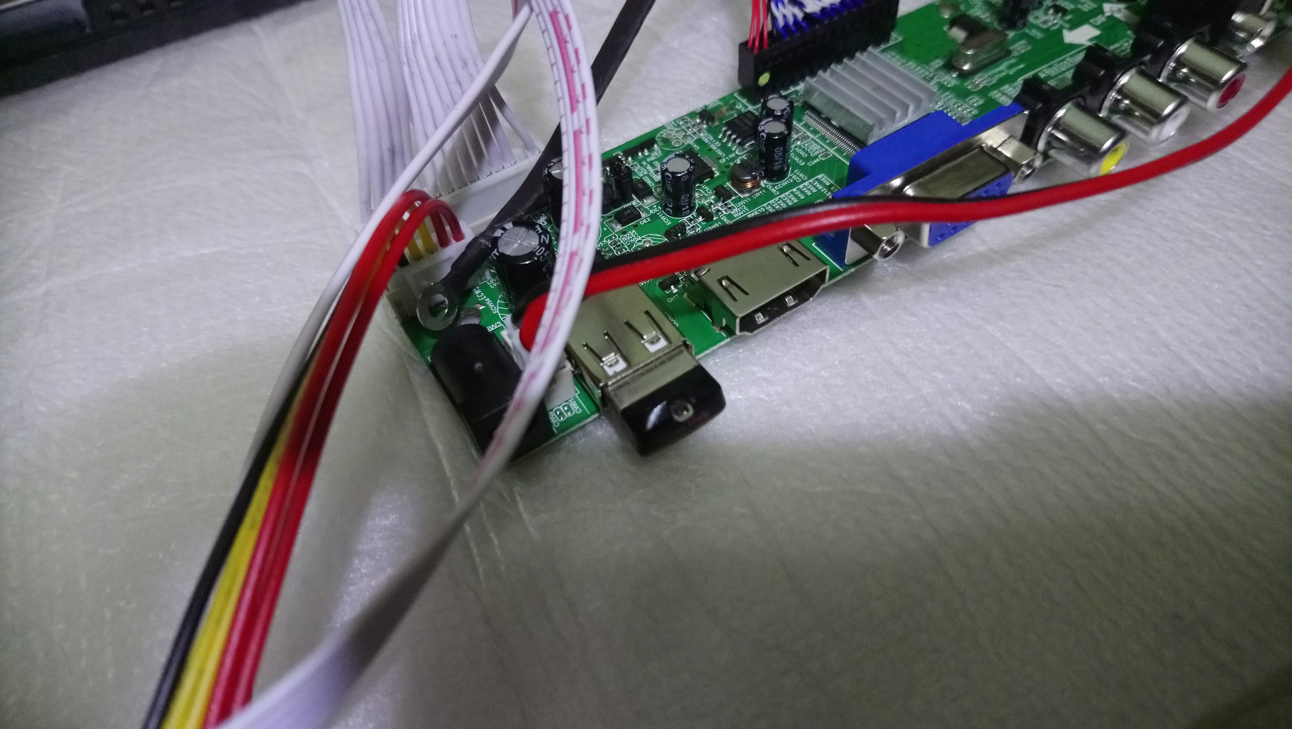
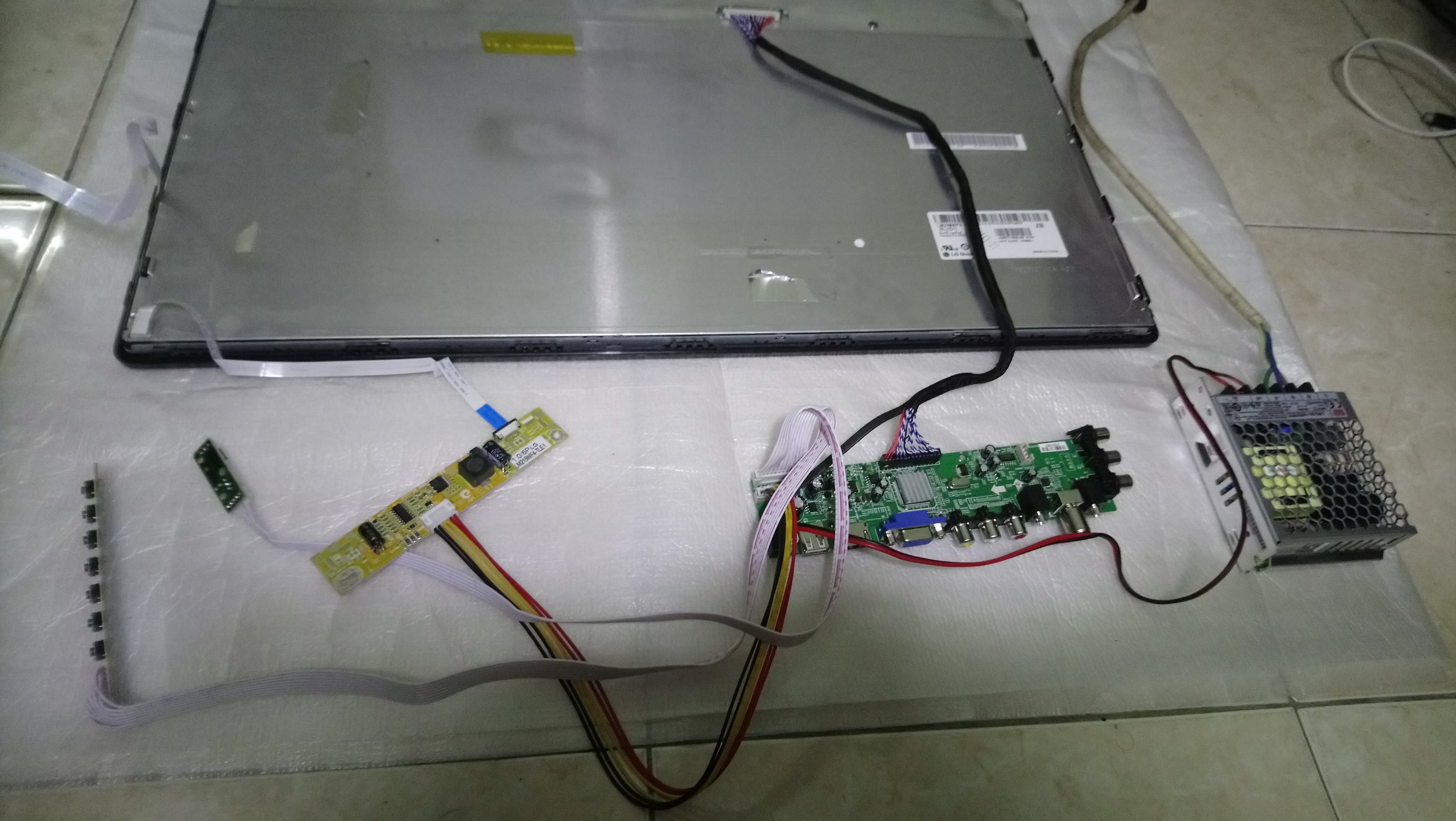
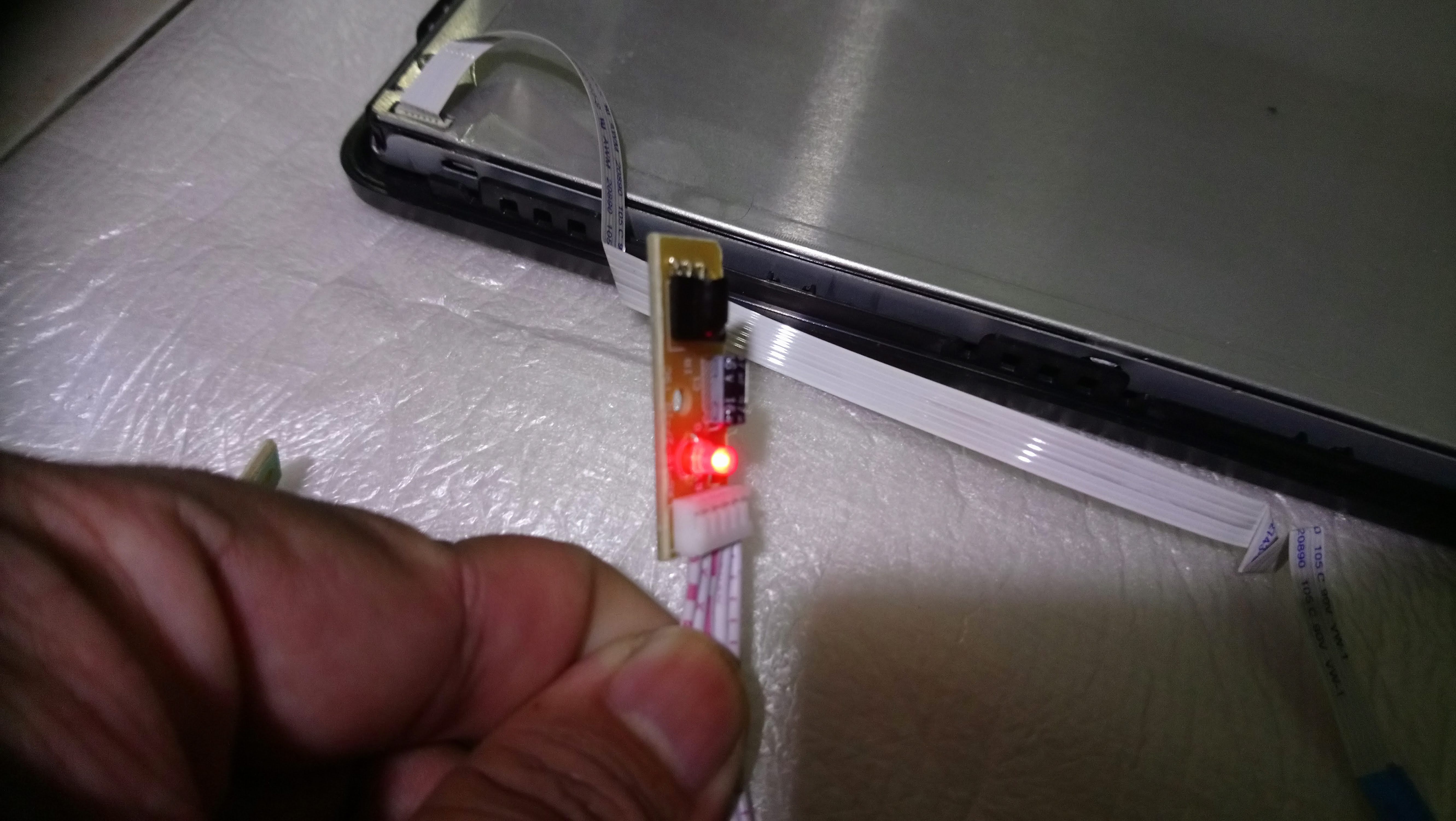
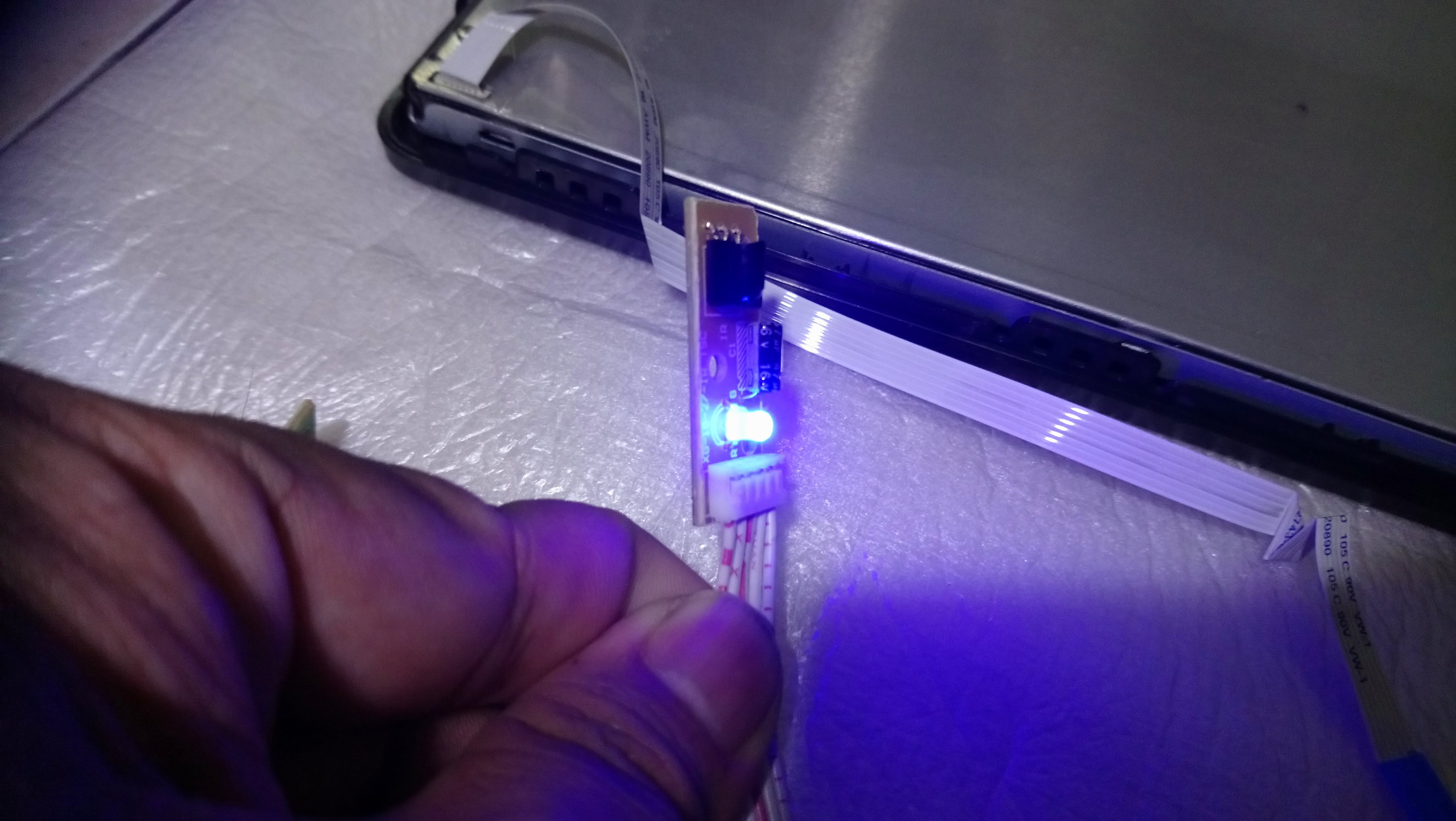
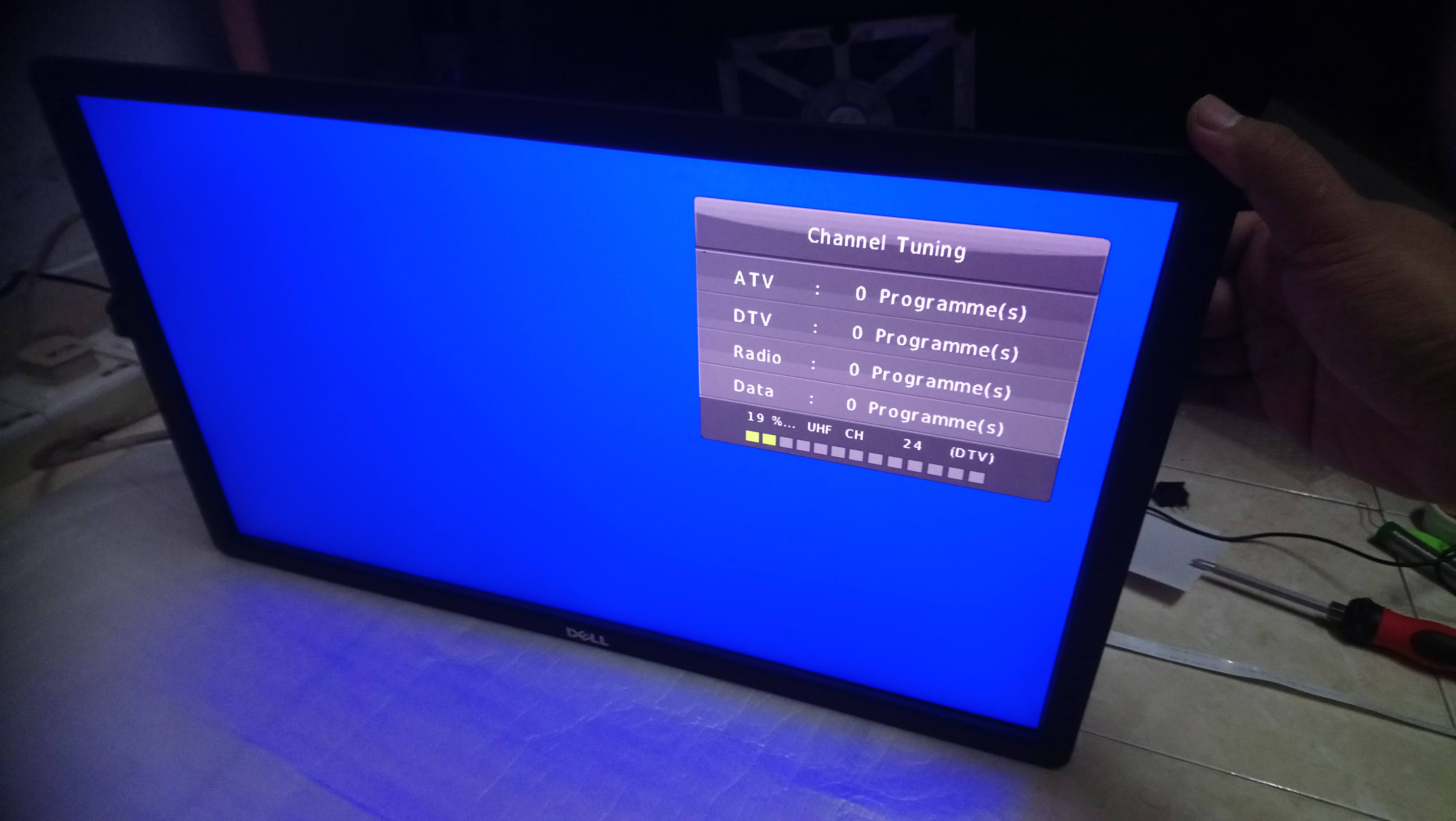
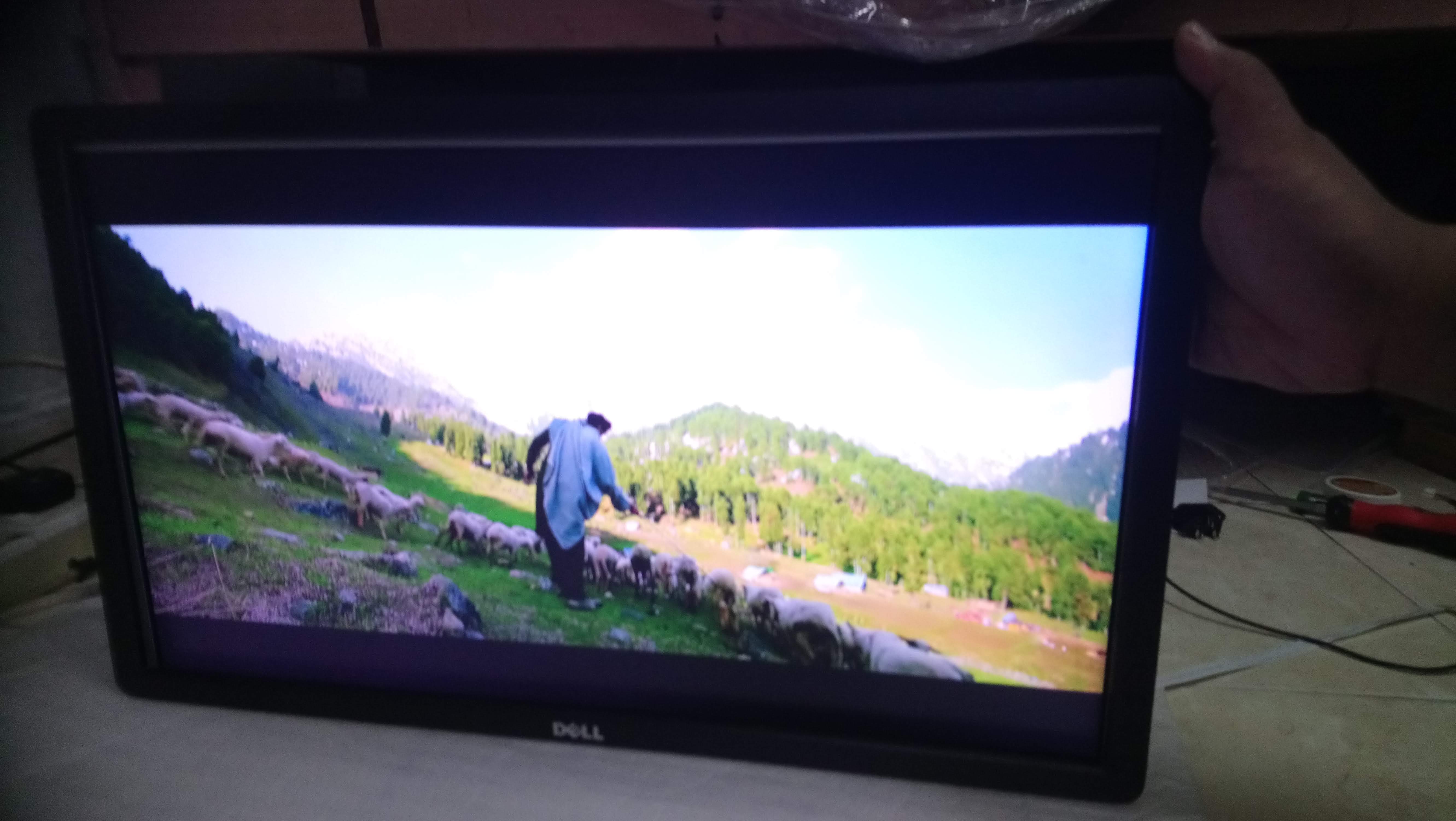
6. After communicating with seller and purchasing process. The kit arrived and now testing process.
7. Connect the LVDS to LCD panel and main board.
8. Connect the LED driver to panel and main board.
9. Download the firmware.bin from supplier (seller will give you) and save to USB drive.
10. Plug the USB drive and turn on the power for the FIRST TIME.
11. The power LED will blink red and blue about 1 minutes indicating firmware installation. After installation complete the screen will boot up.
12. In my case, I'm playing some movie inside my USB drive, and its working.
Fitting
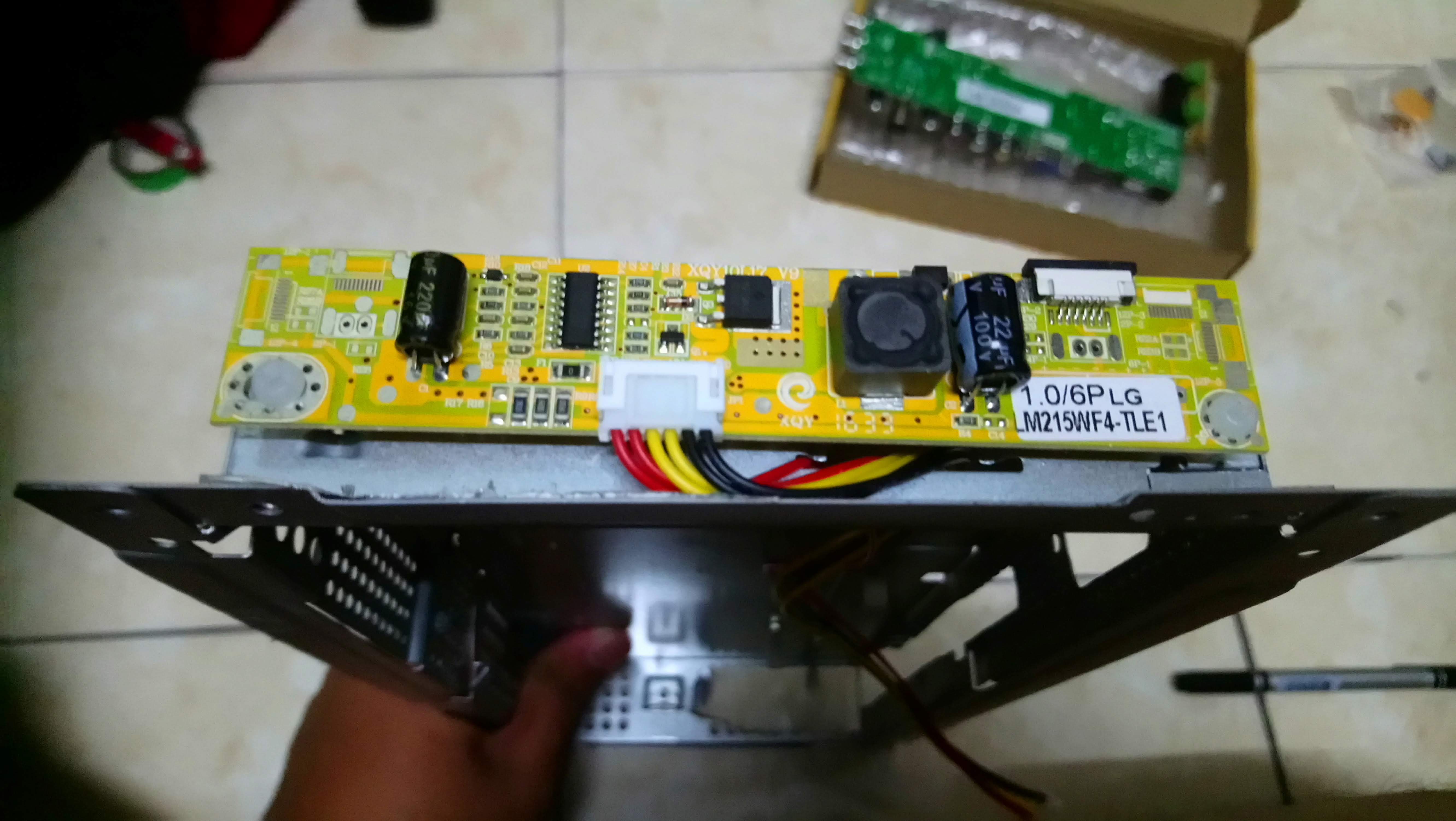
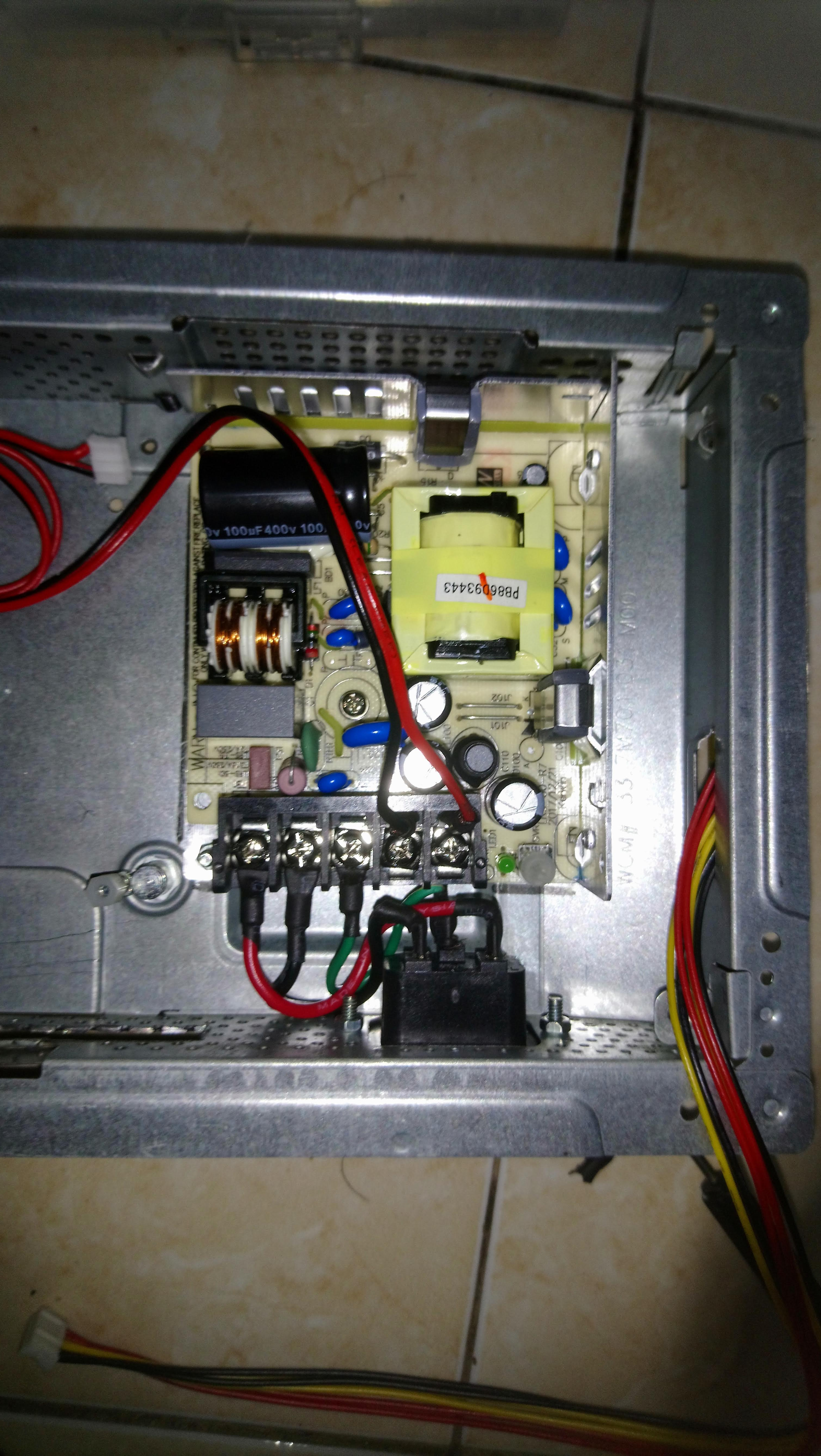
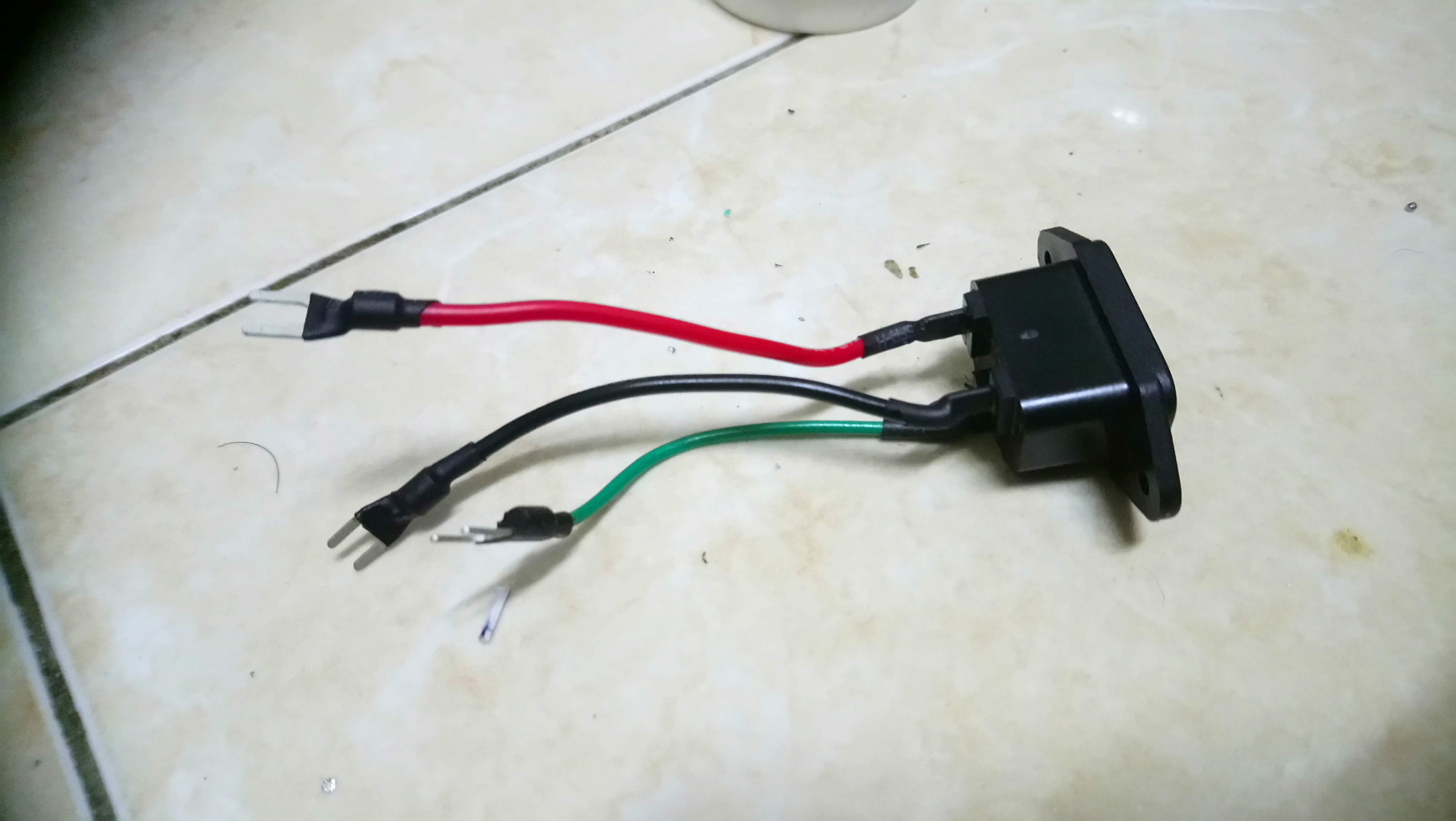
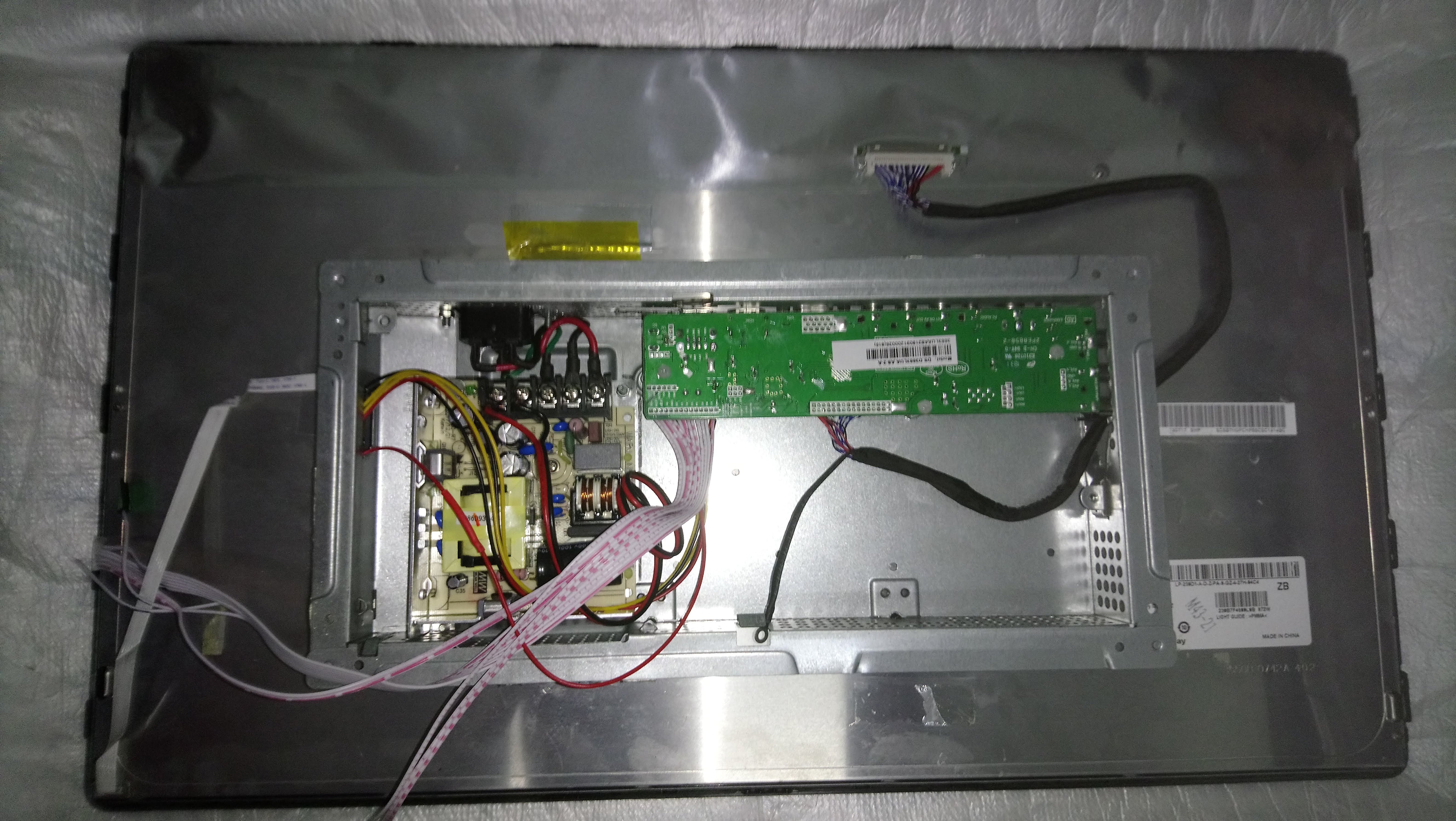
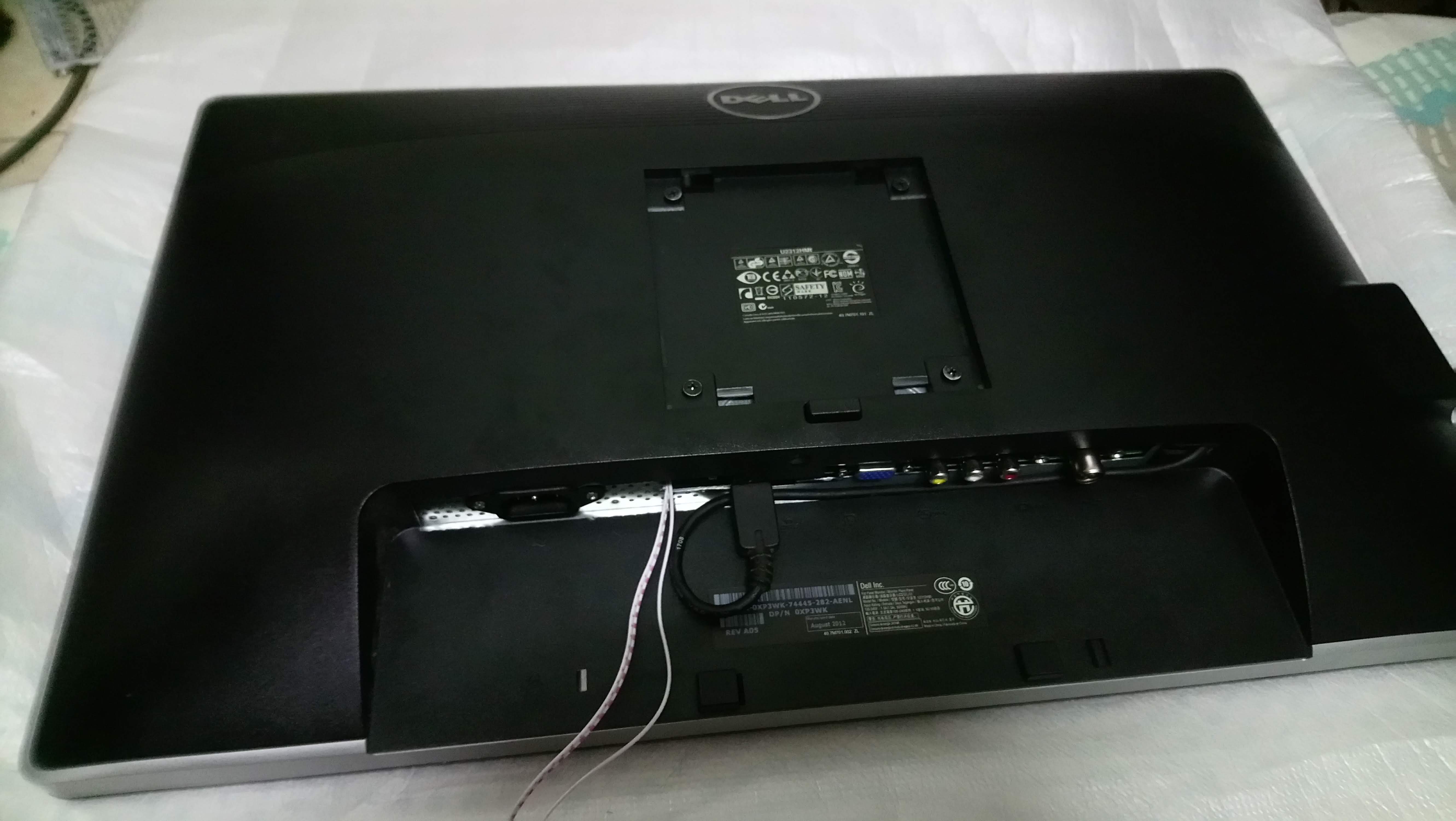
13. Now fitting the system into one package. the board placed and marked for mounting including ports. The unnecessary area removed using grinder and the board mounted using PCB stand-off
14. Fit the LED Driver at side of the chassis.
15. The DC power supply mounted into the chassis.
16 . The main board placed down as original position, port are facing down.
17. IEC power socket (purchased separately) are soldered and connected to power supply.
18. The system button (7 key button) modified to fit original button at monitor (no picture)
19. After connecting the cables, the main chassis is closed and screwed.( don't forget the remote sensor)
20. Now turning ON...
Downloads
Testing
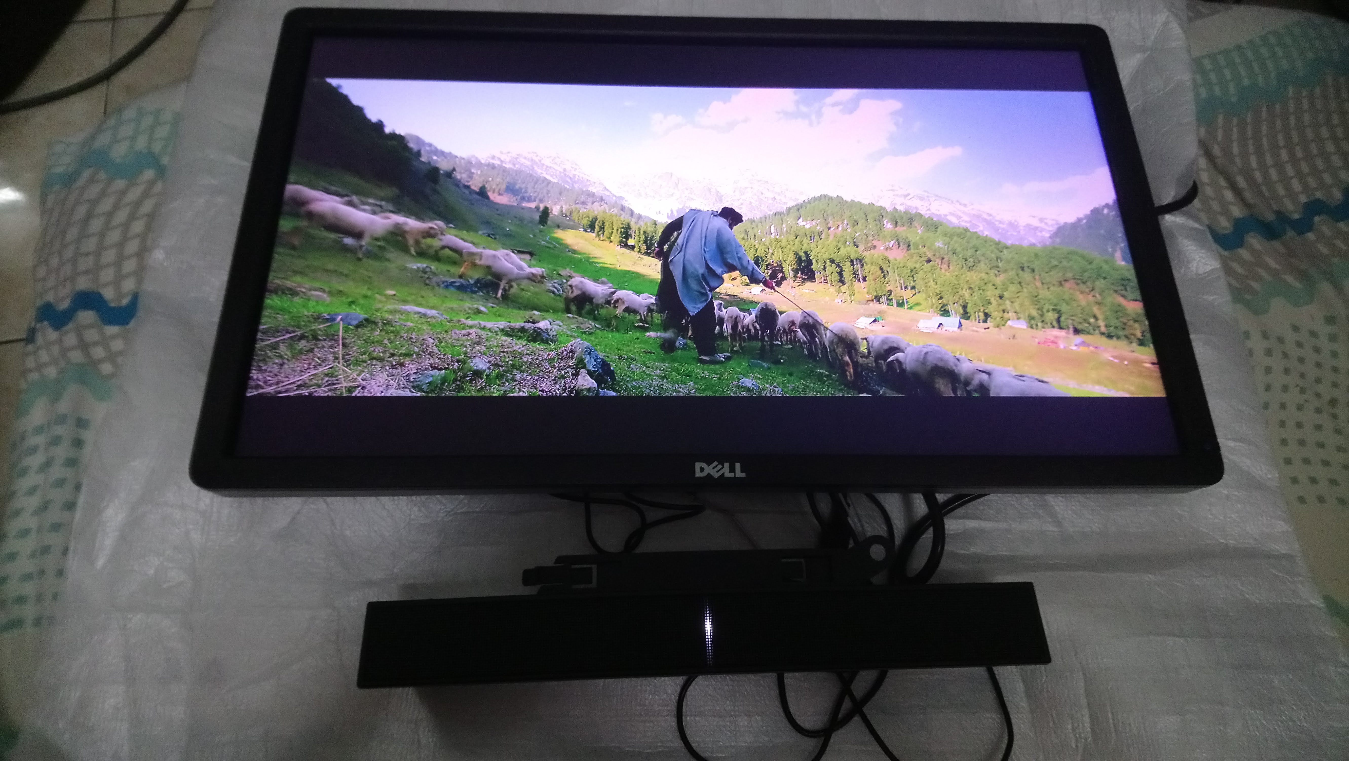
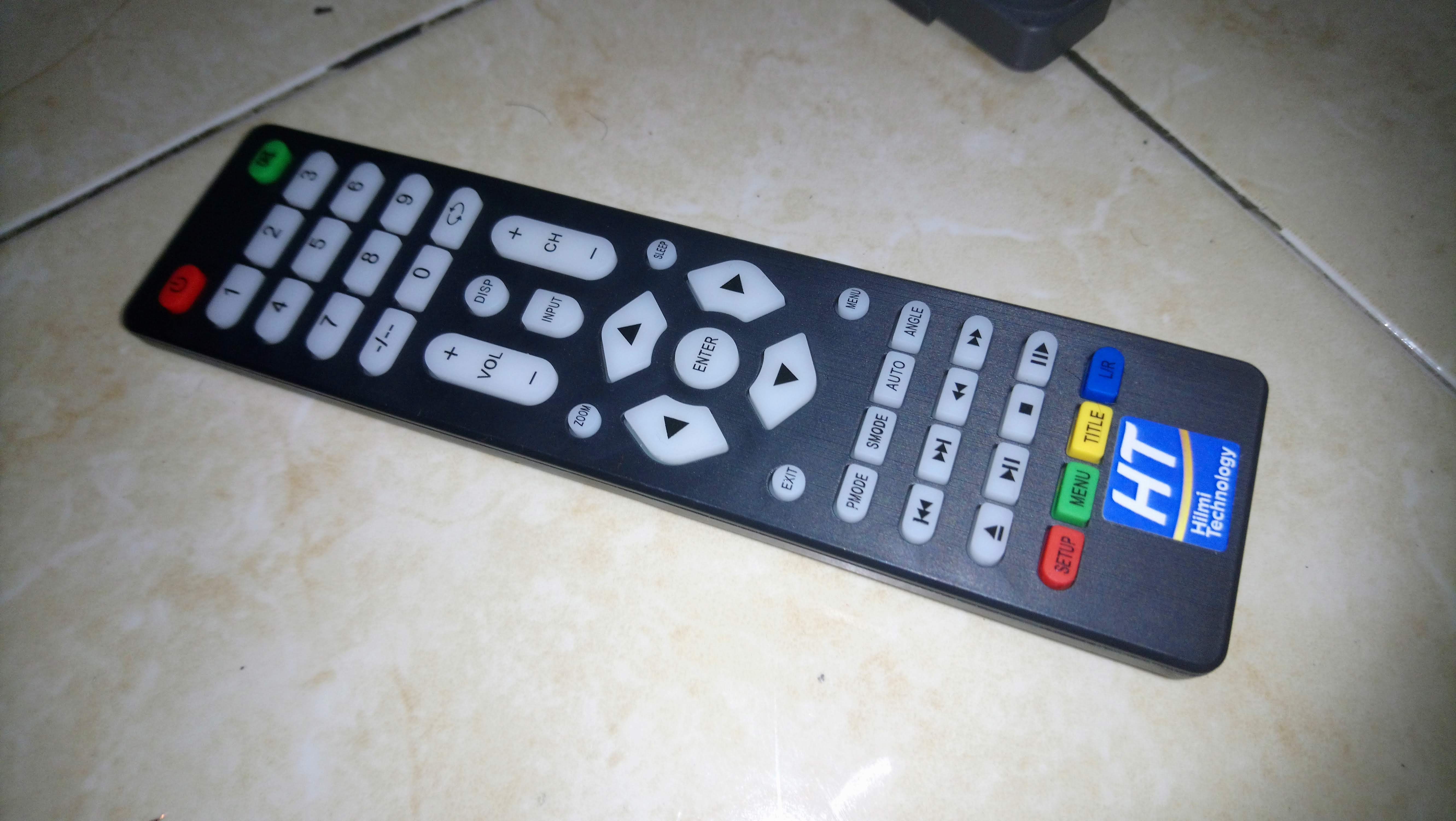
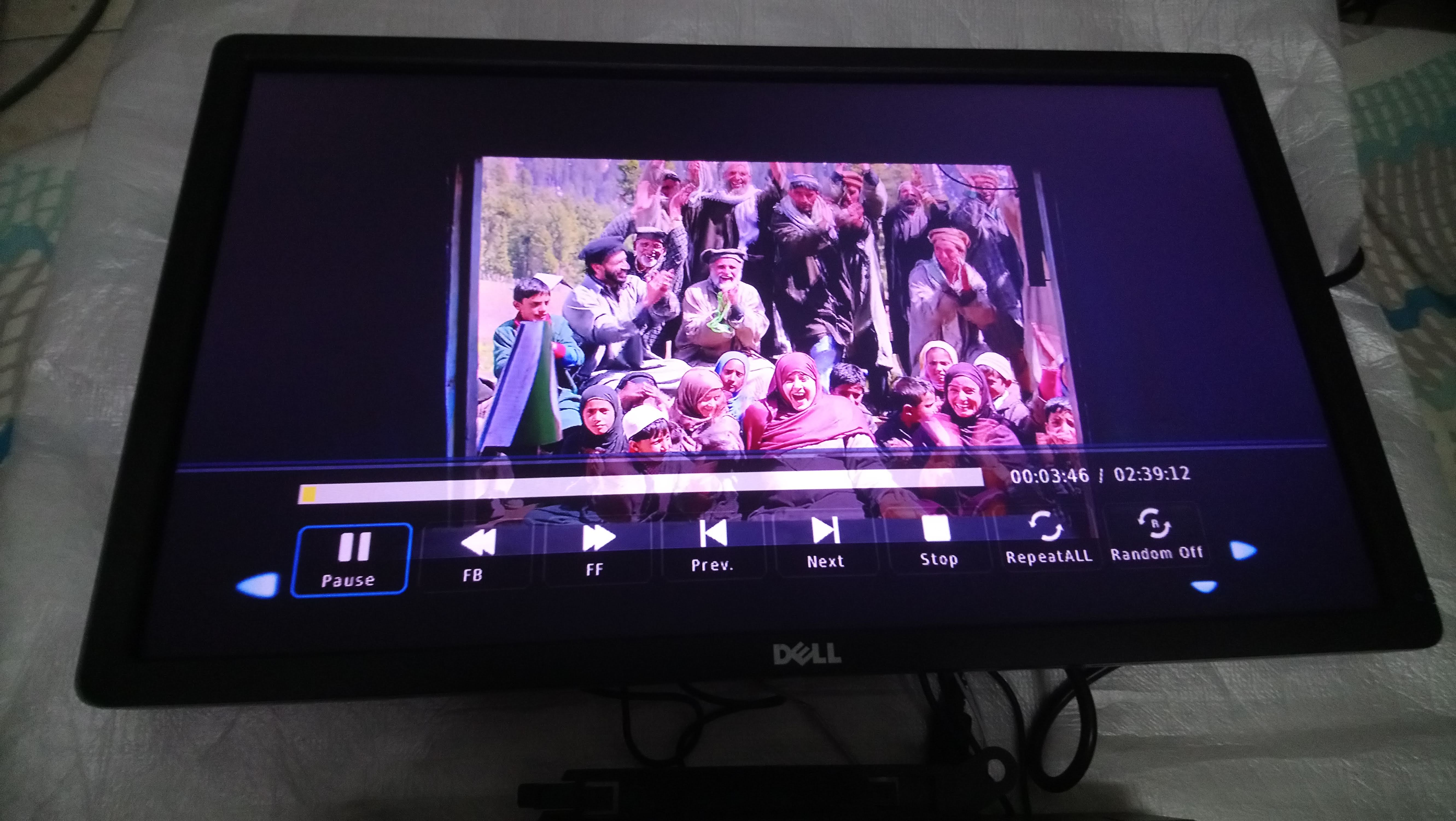
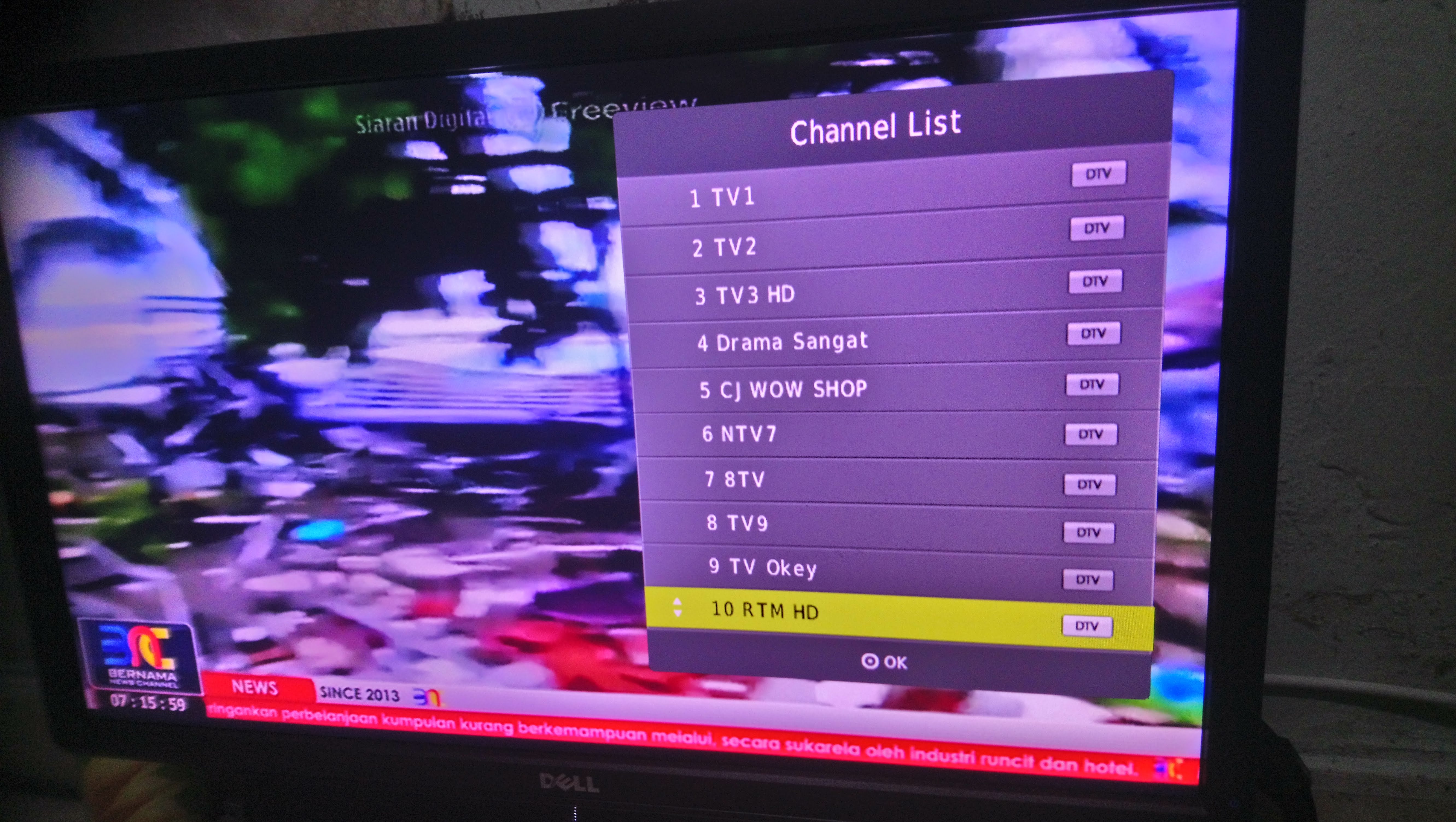
21. Playing some movie in my USB drive - PASS
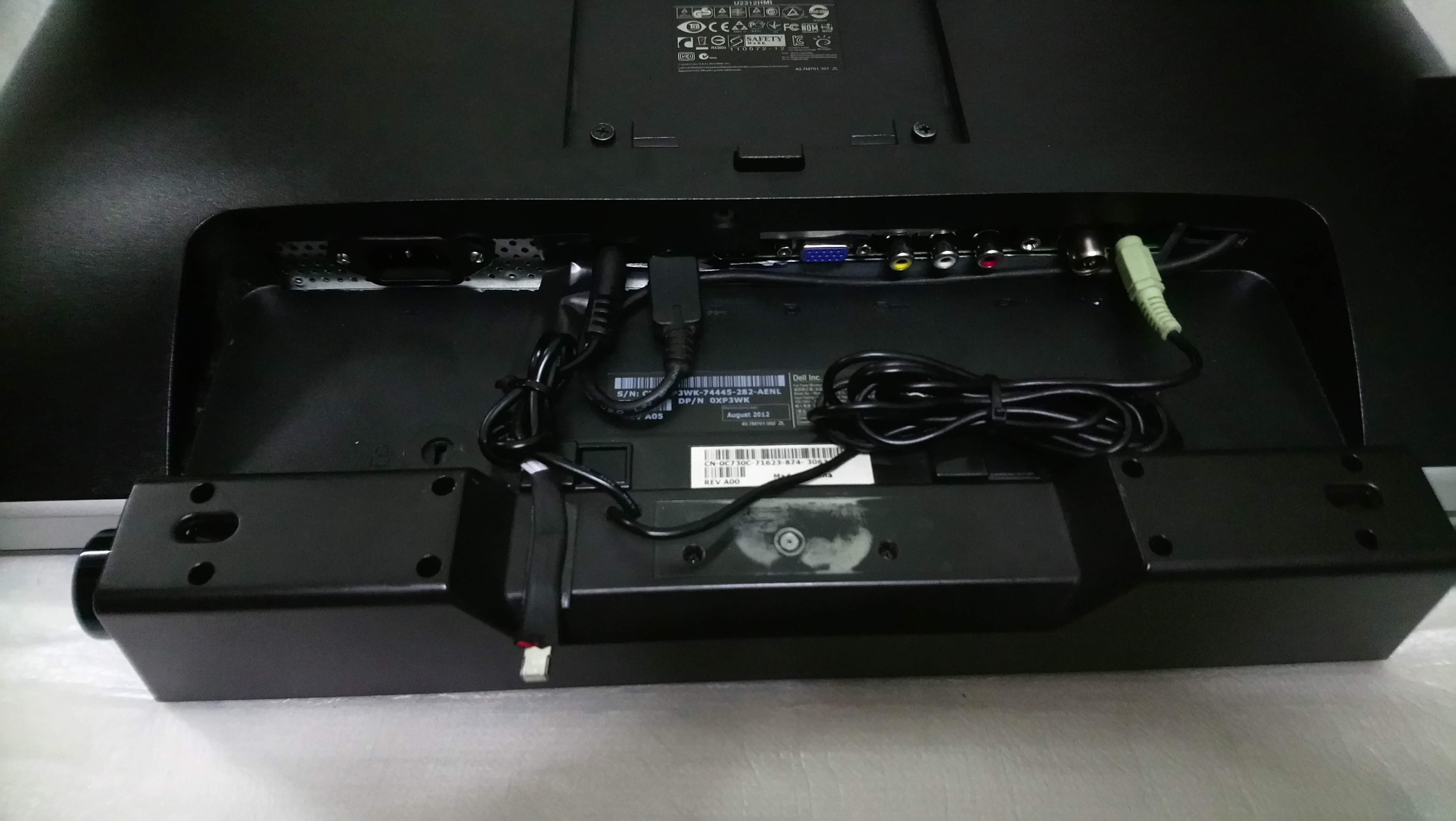
22. Fitting original DELL sound bar - since this monitor doesn't have built-in speaker
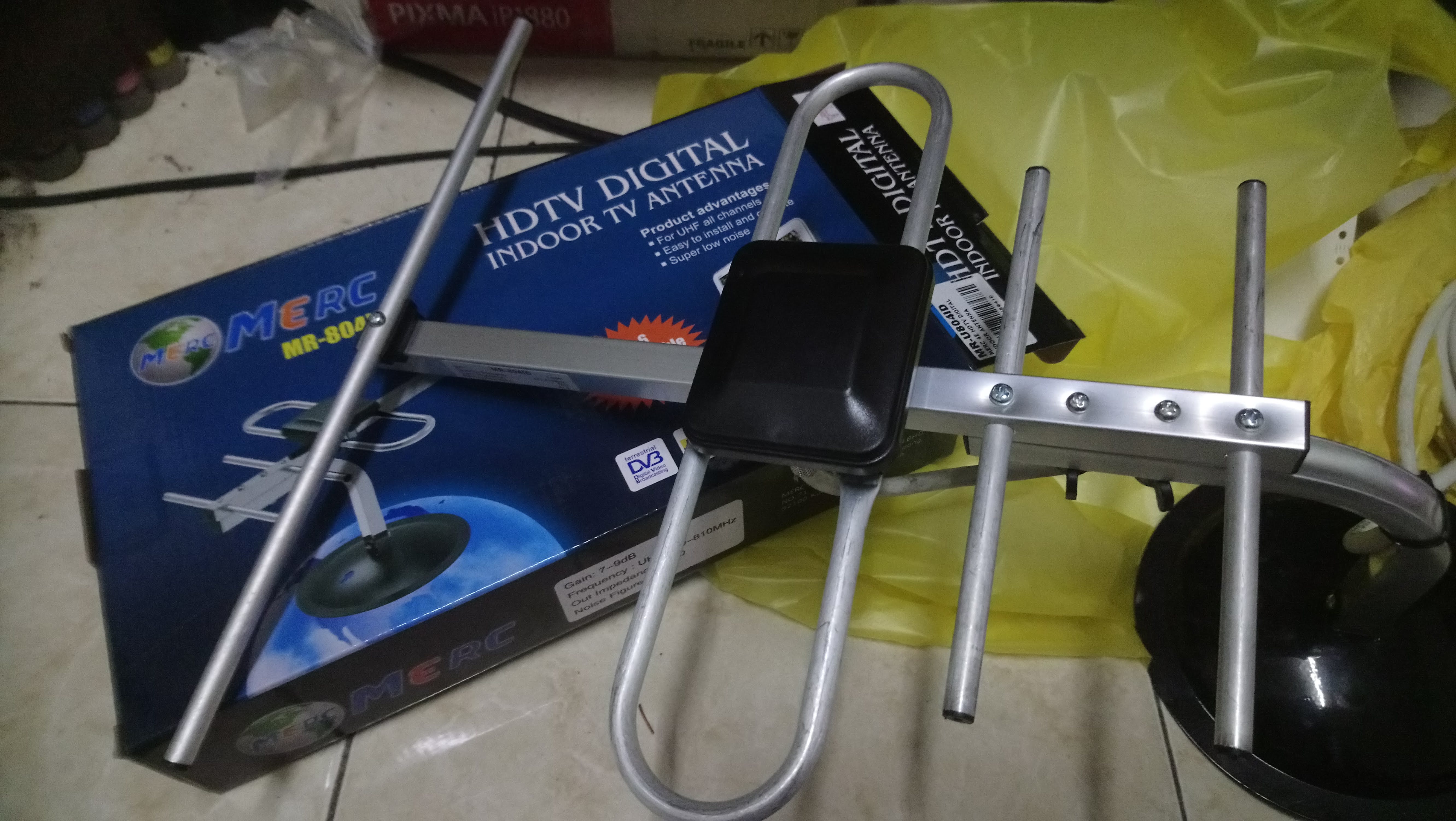
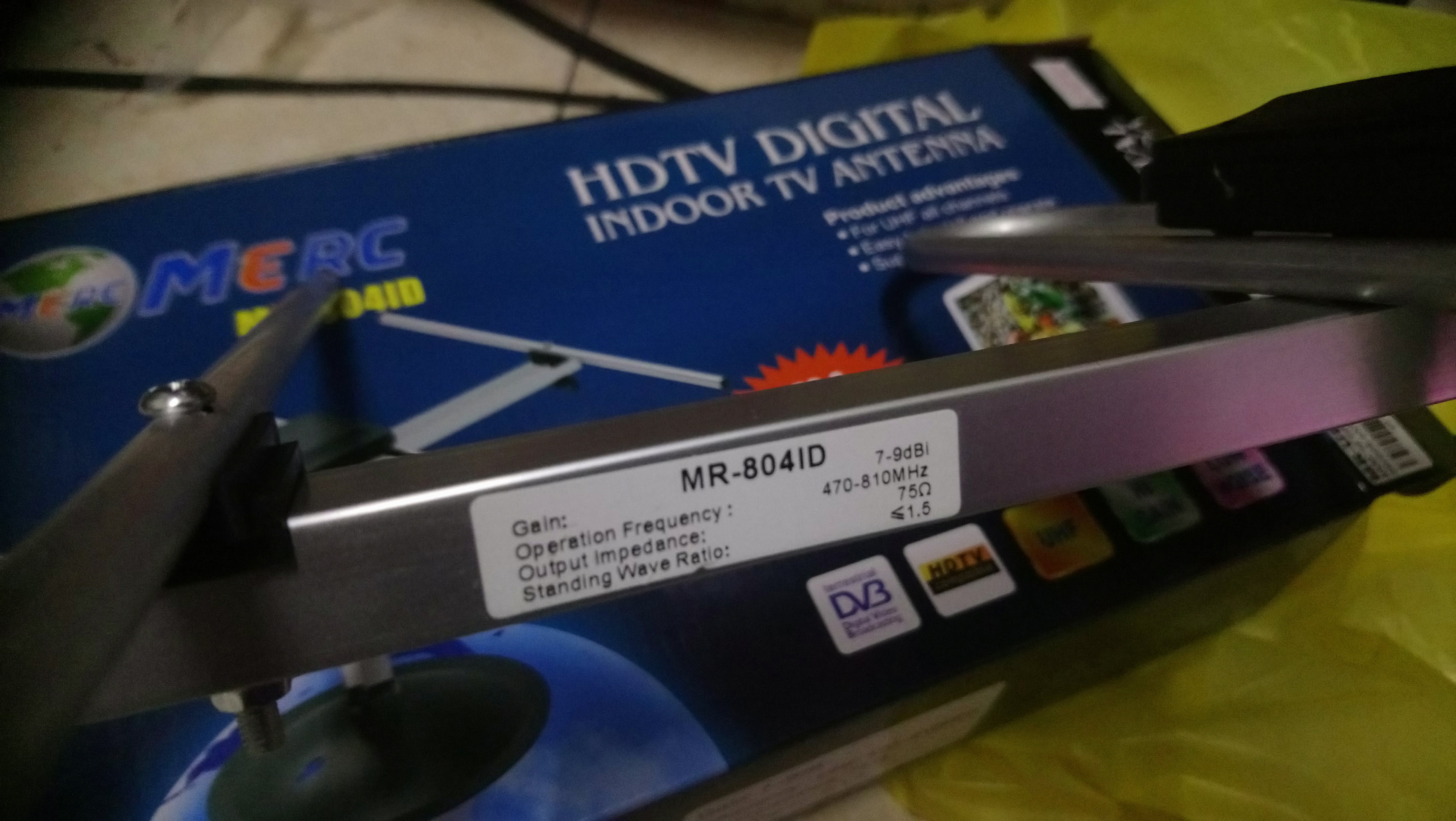
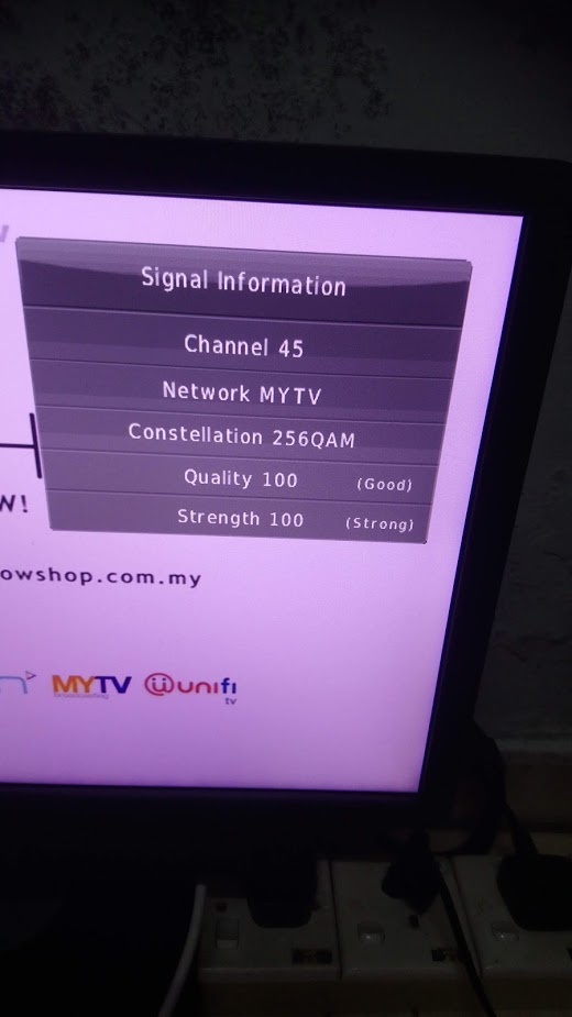
23.Getting proper antenna for HDTV as here in Malaysia we're currently implemented digital signal DVB-T2 known as MYTV
24. Working well as signal and quality 100%
25. as its have many input - you may connect the screen with video player and computer too.
26. Happy recycling and watching..