Modular Hi-Fi Speaker System (New Media Art Project)
by jcunni19 in Workshop > Home Theater
871 Views, 2 Favorites, 0 Comments
Modular Hi-Fi Speaker System (New Media Art Project)


INTRO
As a creator who is really passionate about physical acoustics and elctroacoustics, I have been greatly inspired by the works of artists/engineers like Devon Turnbull (OJAS), Mo Yasin, and Tom Sachs. All of these artists have been deeply influenced by Hi-Fi/DJ culture and have taken a dive into sound reproduction as not only a science, but as an art form. A lot of them have this very scientific understanding of sound that they have paired with a very creative and artistic mindset to create their projects.
I started college as an Audio Engineering Major and completed two years of the coursework for that degree. The coursework taken was a little bit about mixing/mastering/production, but for the greater portion it gave me a really solid understanding of basic electronic, acoustics, and some digital signal processing. When I changed out of the major, I was finding that the work in the realm of CS and more intense engineering was both harder to grasp and not as fun to think about. Despite this I was still very connected to Audio and Acoustics as a major part of my interests and I didn't want to let that go. Over the Summer after I dropped the AME Major, I worked as an Assistant Studio Engineer and did a bunch of Wall Tie Repairs, furniture assembly, and signal flow design under the instruction of a Professor and Masters student who led the renovation of the two studios. In my free time I worked on my own music and started thinking about building speakers as it had been one of the areas that made some sense to me. I really learned a lot of technical skill in that time and began thinking more as a designer than just a technician.
That same Summer I went to Devon Turnbull's Dream Hi-Fi Listening Room No. 1. There I was really inspired to try experimenting with sound and space a lot more. I also realized there is very little accessibility when it comes to experimenting with sound in the world of Hi-Fi despite the fact that it originated with a very DIY culture in the 60's and 70's. That being said I started work shopping my idea for a DIY Modular Hi-Fi System.
PROJECT ABSTRACT
I want the DIY Modular Hi-Fi System to encourage experimentation with placement/arrangement of speakers the way that old hi-fi systems used to. The current products available and oppertunities for experimentation are gatekept by location of listening rooms and money/accessiblity to equiptment that often comes prepackaged. To figure out what kind of sound you like for the space availible to you, this project offers a large woofer, a mid-size woofer, and a tweeter. Because of their seperate enclosures with independant inputs, there is a lot of control over placement, amount of sound/drivers, and crossover. I use a modular crossover with a variable frequency and the option to use 2 or 3 drivers. This provides the option to experiment and develop a preferance on how your different frequency ranges get reproduced and how powerful each section is.
Supplies


COMPONENTS
- 1x Super Tweeter Horn
- 1x 8-inch Speaker Driver
- 1x 12-inch Speaker Driver
- Several feet of Speaker Wire
- Silver solder (or any conductive electrical solder)
- 1/4 inch Female TS/TRS connector (2 to screw into enclosures and 1 to make a cable end)
- Quick release connectors
- 3x Sheets of MDF or Ash Wood (4'X8')
- Acoustic Foam/Insulation/ Dampening Materials
TOOLS
- Buzz Saw
- Rotar
- Drill - with different bits to drill holes or drill in screws
- Wood screws
- Hammer and nails
- Wrench
- Nuts, washers, screws
- Fastening mount
- Wood Glue
- Soldering Iron
- Clamps and Heavy items (not necessary, but can help when the glue is setting and with propping up walls)
- Flex Putty (not necessary but can correct for errors)
Gathering of Electronics and Materials


I started by selecting the electronic components of the system.
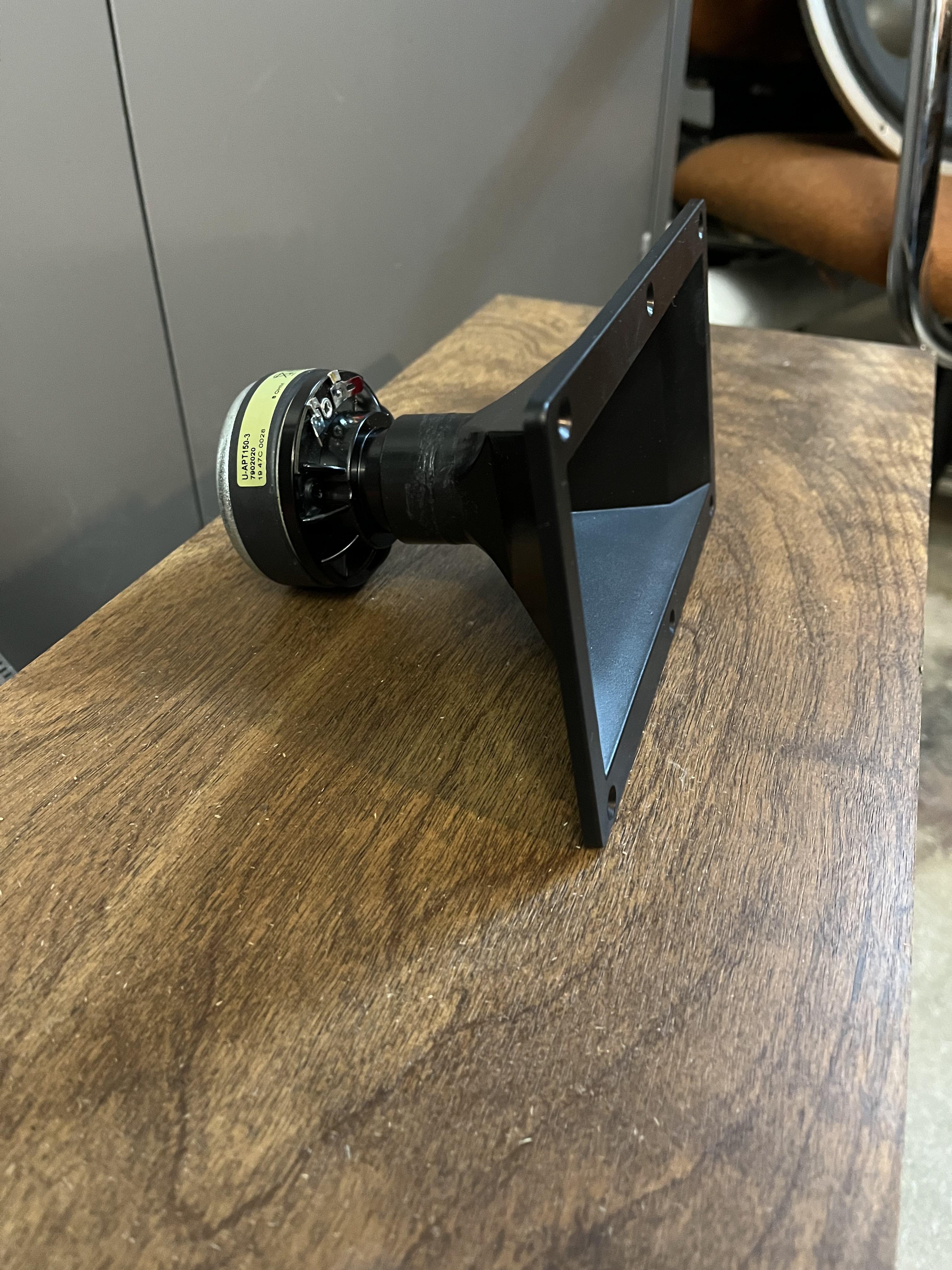
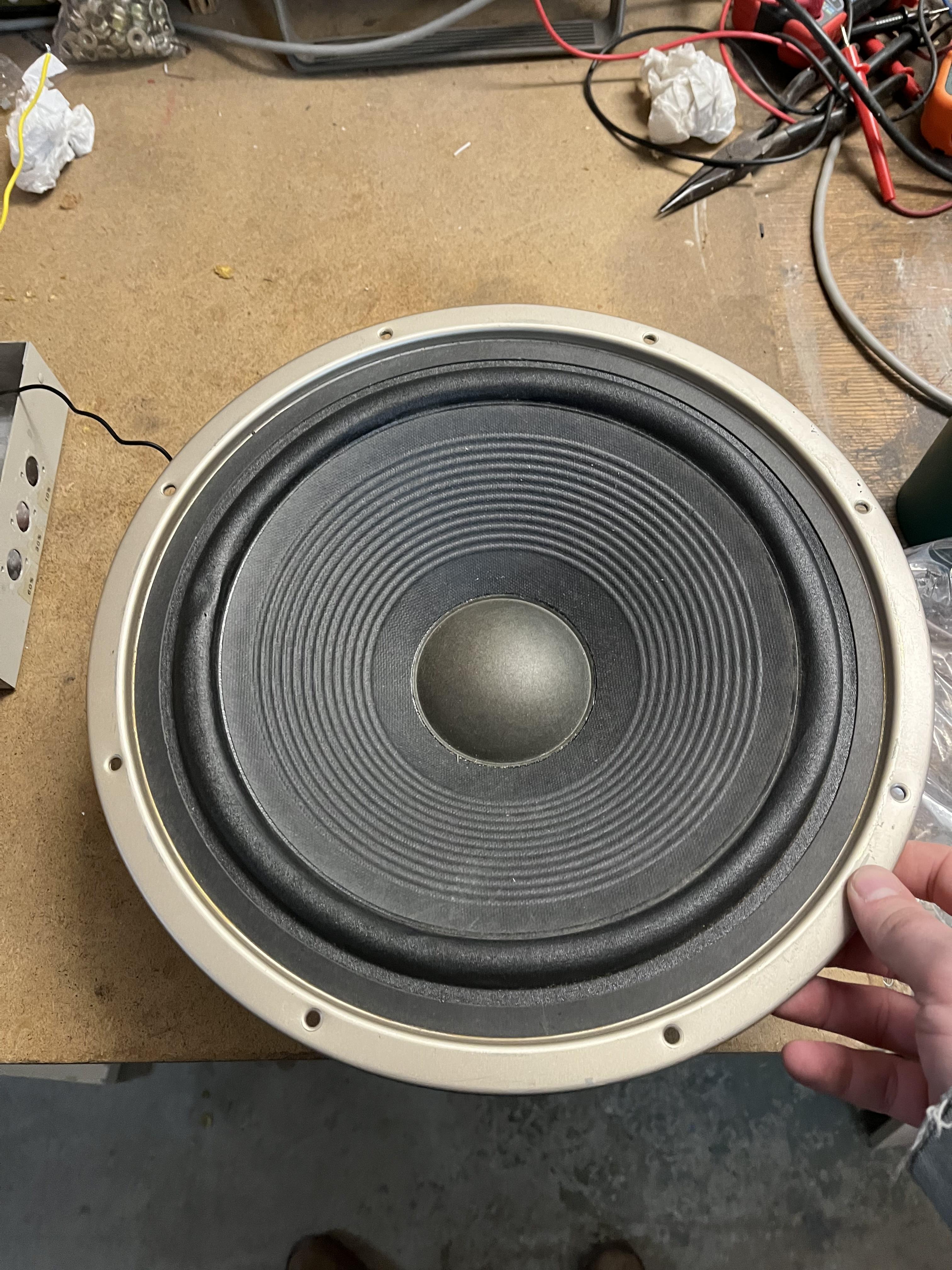
For this project, I used a salvaged Sony 12-inch Woofer for the low-end (alt full-range), a new GRS 8-inch Woofer for the midrange (alt full-range), and a new Eminence APT-150 Super Tweeter (high-mids/high-end).
All of these components are matched impedance at 8 Ohm's making them easy to put into parallel. In the two charts above I have illustrated the math for putting 2 of the drivers through a crossover in parallel versus 3 of the drivers through a crossover in parallel.
Because the objective of this project is to make the set of speakers modular in the sense that you can run an amplified signal through either a 2-way or 3-way crossover out to any variation of speakers, the matched impedance creates consistency on power drawn by each speaker in each configuration.
Designing/Building Your Enclosures


DESIGN
First, determine how much volume you want your enclosure to have.
For this project I saved a bit of time and went with some rough approximations based on Theile-Small Parameters of the woofers that found using an online calculator.
Demo: GRS 8inch Woofer
The Thiele-Small parameters of the GRS 8PR-8 8" Poly Cone Rubber Surround Woofer are:
- Fs (resonant frequency): 57 Hz
- Qts (total Q factor): 0.39
- Qes (electrical Q factor): 0.44
- Qms (mechanical Q factor): 4.7
- Vas (equivalent compliance volume): 20.2 liters
- Xmax (maximum linear excursion): 3.25 mm
- Sd (effective diaphragm area): 214.5 cm^2
- Re (DC resistance): 7.1 ohms
Using the parameters provided, we can calculate the recommended box volume for a sealed enclosure using the following formula:
Vb = (Qtc / ((2 * π * Fs)^2 * Vas))^0.5 - Vas
Assuming a desired Qtc of 0.707 (Butterworth alignment) and using the Thiele-Small parameters provided, we can calculate the recommended box volume as:
Vb = (0.707 / ((2 * π * 57)^2 * 20.2))^0.5 - 20.2
= 6.47 liters
For a sealed enclosure, we can use a rectangular box design with internal dimensions of 11.6" x 8.7" x 7.6" (width x height x depth) to achieve a box volume of approximately 6.47 liters.
After getting an aproximate volume, I looked around at some other designs and went off of Devon Turnbull's more cubic design. My sizes wound up being aproximately 16" cube and a 22" cube. This wasn't quite perfect, but it worked for the goal of the project.
I also chose to use MDF as it is a traditional speaker enclosure material that is proven highly effective.
ASSEMBLY
From there I cut out the walls from the sheets of MDF using a buzz saw and some marking chalk.
After Completing my cuts I used wood blocks and different other square shapped objects to create braces/props while I secured the pannels into place with a healthy amount of wood glue.
Adding Wiring and Inputs


Using a drill I cut out some holes sized to fit a 1/4-inch input that I fastened into place with a washer and a nut.
After doing that I soldered on one end of my wiring to the +(tip) terminal and -(sleeve) terminal of the female 1/4-inch connector. On the other end of the cables, I soldered on two quick-release clips.
Making Front/Back Panels

Using a router, I carved out a square for the back plates and front plates to provide access through the back of the enclosure and also so I can mount the speaker drivers inside of them.
Mounting Drivers


I over-cut a bit with the router for the driver holes so there were some creative solutions developed.
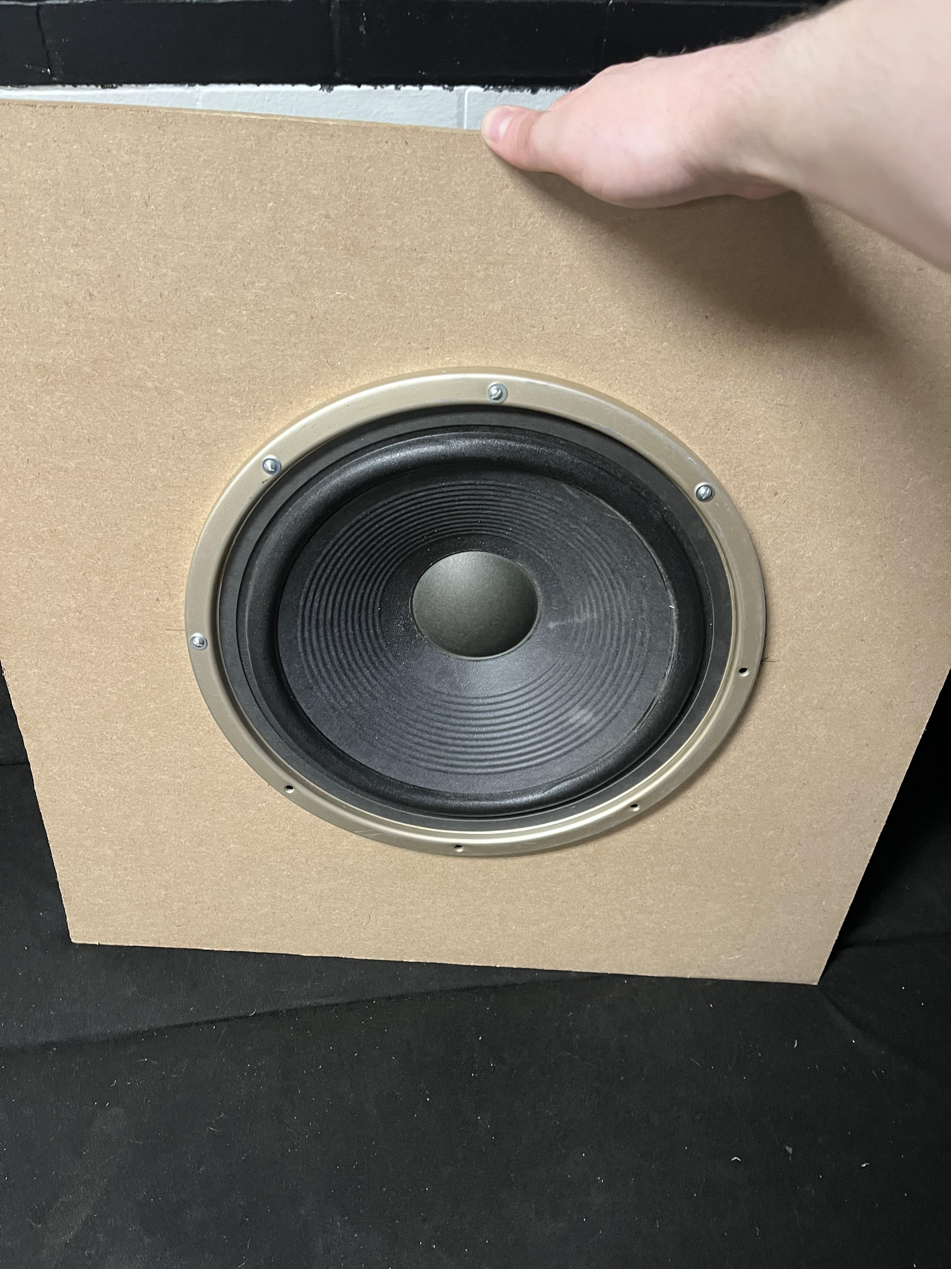
For the 12-inch woofer, there was enough of an overlap to use a drill to carve some deeper holes and then a different drill bit to punch 4-6 securing holes in the wood. Then I fastened the woofer in place with nuts, bolts, and washers.
For the 8-inch woofer, there was no overlap so using security braces, I attached one hole to the driver with a nut, bolt, washer, and a little piece of felt for acoustic dampening and protection.
Attaching Front and Back Panels to Enclosures
***Make sure everything is level using a power sander/belt sander***
Using another healthy amount of wood glue, secure the front and back plates onto the enclosures. If there are any openings or leaks you can use a glue or sealant like FlexSeal to close up any unwanted leaks.
This may dampen the resonance of the box, but I think for a simple correction and the first attempt at this project it worked alright.
(I would advise attaching the back pannel after your drivers are attached to inputs.)
Connecting Inputs to the Drivers
Because we soldered on quick-release clips, all that has to be done is clipping them onto their respective positive or negative terminal and crimping to ensure they remain in place.
Horn Cable

Solder the Yellow (or whatever positive wire you select) to the + (tip) terminal of the TS connector, then solder the black wire to the - (sleeve) terminal
Mounting Horn and Attaching Cable
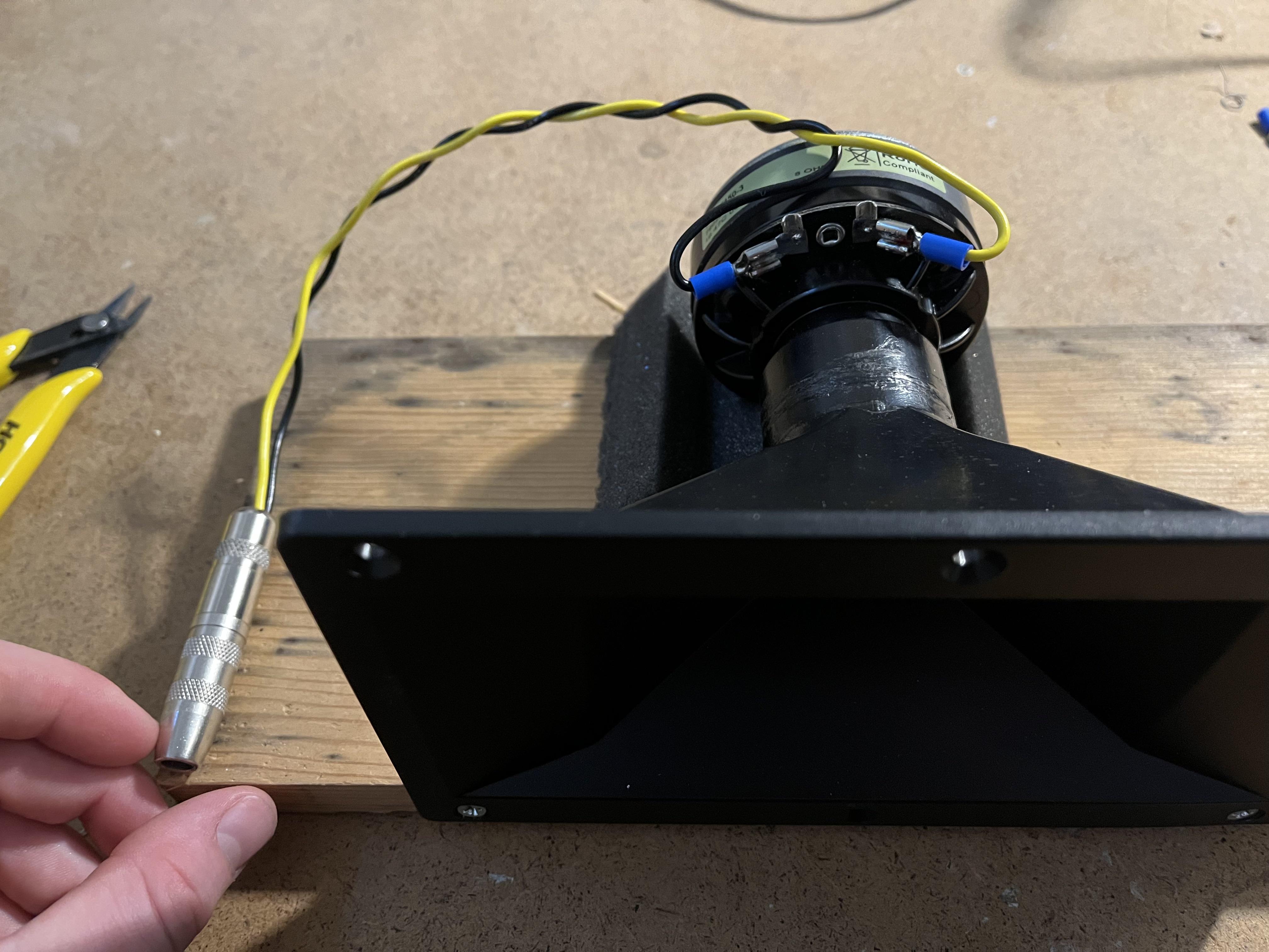


Screw in the bottom of the horn to a 6"x12" plank with some acoustical foam underneath the magnet.
Then grab some wire and attach a 1/4-inch female TS connector to one end and 2 quick-release clips to the other two ends of the speaker cable.
Then just clip and crimp the quick-release connectors to the two terminals on the driver (labeled + and -).