Modifying a Nikon SB-600 Speedlight to Rotate Further
by dan_f in Circuits > Cameras
10562 Views, 2 Favorites, 0 Comments
Modifying a Nikon SB-600 Speedlight to Rotate Further
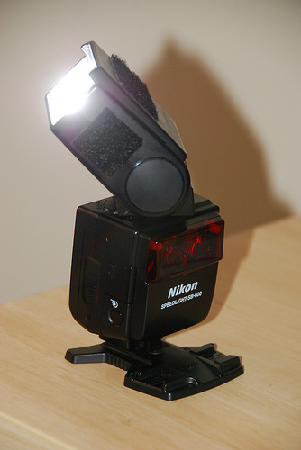
The Nikon SB-600 and SB-800 Speedlight flashguns both have a fundamental problem. The flash head can be rotated 180° counter clockwise (viewed from the top), but only 90° clockwise. This is a major disadvantage when shooting portraits whilst using an extended battery grip as you can't direct the bounce flash above and behind you.
There are a couple of modifications for the SB-800 to overcome this problem but there were none for the SB-600, so I decided to find one.
Important Notes and Disclaimer:
If you're going to do this mod, please read it through carefully before you begin.
There is high-voltage circuitry inside the flash gun and a chance of an electric shock. I got zapped a couple of times making these mods so please be careful. I've indicated the zappy bits.
This modification involves grinding out part of the inside of the flash gun, it will void the warranty on your expensive flash and Nikon will know if you've taken it apart. I've taken care to document every step, and I have completed these instructions once but I can't be responsible if you stuff your flash or if you get zapped.
Tools
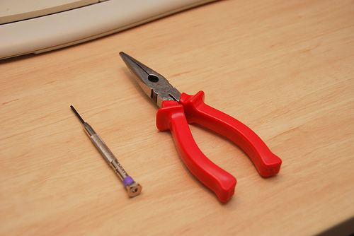
You'll need the following
- Dremel with a #420 Cut-Off Wheel and a #115 High-Speed Cutter (or similar)
- Needle-nosed pliers, small to middle sized
- No. 00 sized Philips screwdriver or jewelers screwdriver
Note: It's probably best to use a larger handled screwdriver than a jewelers as the screws have had thread-locker added to them. You must make sure that your screwdriver fits the screws perfectly as they're very stiff and you'll need to apply quite a bit of force.
Removing Lower Screws
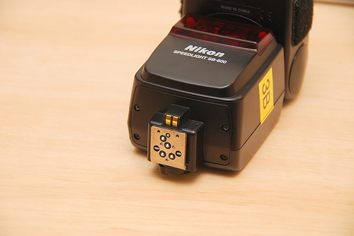
You will need to loosen all four of these screws (mouse over) by a quarter turn. Be warned though, the screws in my Speedlight had been secured with Loctite and were extremely hard to start turning without stripping the heads. Make sure you have the correct sized screwdriver and you push on the screws hard to stop the screwdriver slipping out.
Once you have loosened all four, remove the upper two shown in the notes.
Once you have loosened all four, remove the upper two shown in the notes.
Upper Screws
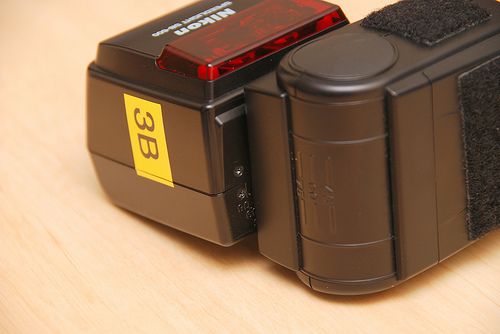
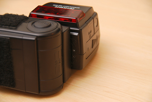
The 4 upper screws are covered by the flash head, rotate it 90° to access them
Loosen both of these screws by a quarter turn and remove the top screw as shown in the notes. Again these had been secured with Loctite and were very hard to undo initially so make sure your screwdriver fits properly or you'll destroy the screw head.
Loosen both of these screws by a quarter turn and remove the top screw as shown in the notes. Again these had been secured with Loctite and were very hard to undo initially so make sure your screwdriver fits properly or you'll destroy the screw head.
Removing the Cover
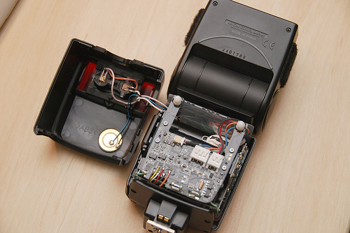
Gently ease the cover off the flash and put it to the side shown. You will have to route the cables that connect the cover behind the LED shown in the notes in order for it to lie flat.
Try not to disturb the plastic cable envelope just yet.
Try not to disturb the plastic cable envelope just yet.
Before Continuing
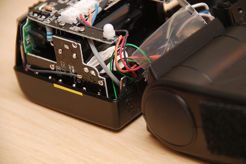
Before going any further take note of a couple of things.
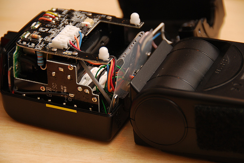
First, there are two of these screw boss plates on either side of the flash (see notes). The reason you only loosened the bottom screws was to stop these falling into the electronics. Make sure the bosses are still attached and won't fall in
Secondly take note of how the cable envelope lies around the cables and where it fits into the body of the flash. The envelope stops the cables tangling when you rotate the flash head and so it needs to go back in the way you found it. Take some photos too if you can.
Dangerous Bits
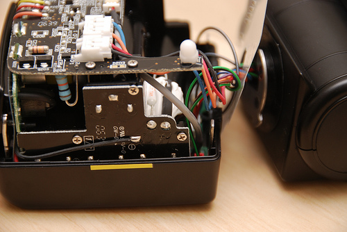
I got a couple of zaps from these contacts even though the flash had been unpowered for 24 hours, so be careful. Although it stung a bit it's probably more important to avoid them in case you fry the electronics.
Also the ceramic paste that looks like toothpaste is actually hard so don't worry about getting it everywhere.
Also the ceramic paste that looks like toothpaste is actually hard so don't worry about getting it everywhere.
Separating the Flash Head
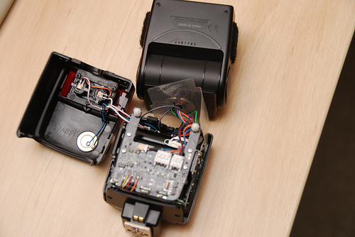
You'll need to separate the flash head from the body of the gun.
Start by pulling out the plastic cable envelope and rotating it to one side.
To remove the flash head, first squeeze the rotate button on the head and lift the head up and out of the flash gun body.
Start by pulling out the plastic cable envelope and rotating it to one side.
To remove the flash head, first squeeze the rotate button on the head and lift the head up and out of the flash gun body.
Accessing the Connectors
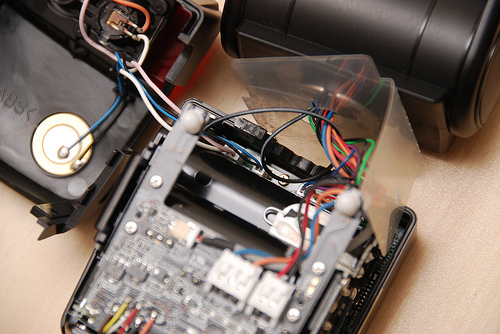
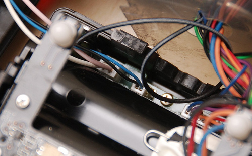
Using the needle nosed pliers, disconnect the two cables shown in the notes. This will allow you to separate the front of the flash gun for Dremel work.
Front Cover Removed
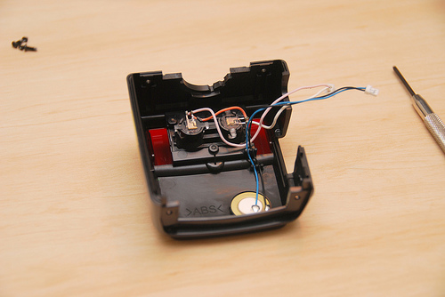
This is what you should be left with after unplugging the connectors.
The Bump Stop
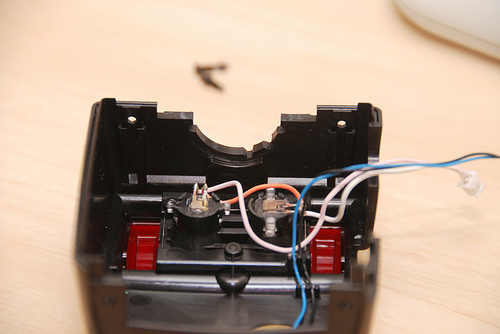
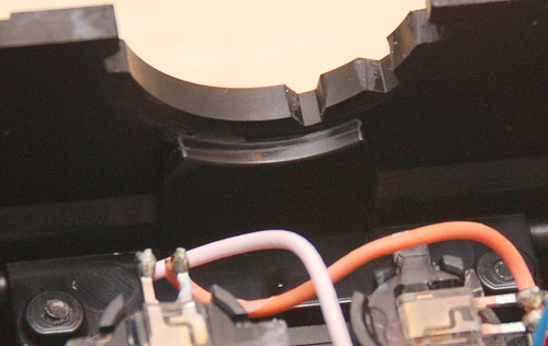
So this is the bit that needs machining. I only ground out some of it so there is still a hard stop to prevent the flash head doing a Linda Blair. I don't know what happens if you remove it all, feel free to do it and hit me in the comments.
Grinding
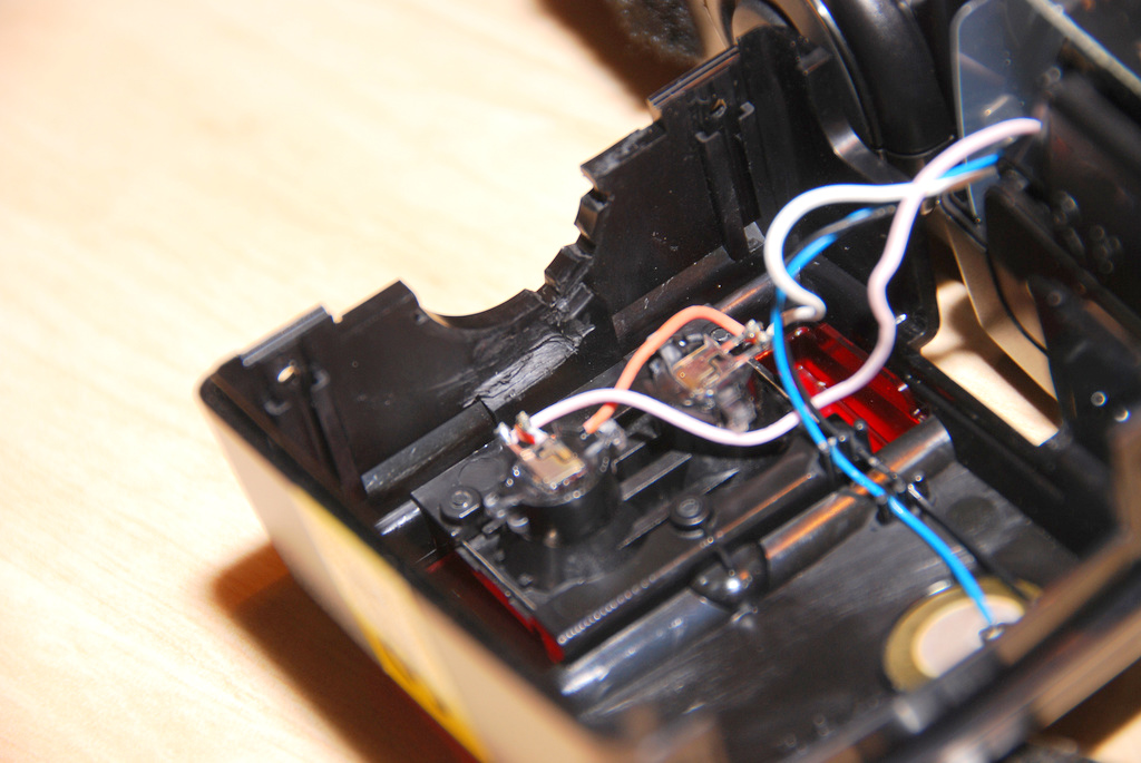
Use the Dremel tools to machine away most of the bump stop, leaving you with something like this. I used the #420 Cut-Off Wheel to start and remove most of the material without affecting the base and the #115 High-Speed Cutter to tidy up the edge and remove the rounding caused by the #420.
I only wanted to add 45° to my rotation so this is all I removed. If you want your flash to rotate 180° then you can grind this stop away. You could probably leave a smaller section as well, but I'm hard on my flash gun and wanted to make sure I didn't snap the bit off.
Use a gentle hand and make sure to use an air gun or something to blow all the plastic dust out of the inside of the cover, that's why we had to separate the cover from the flash housing.
Reconnecting
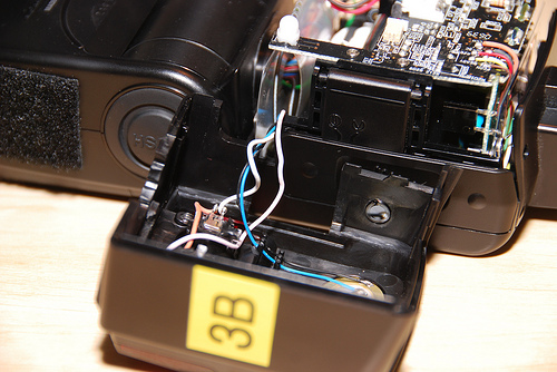
Plug the cables back into position, they only go in one way.
Putting It Back Together
1. Gently fold the plastic envelope back into the Speedlight body. Make sure the long side of the envelope is behind the screw bosses or the screws won't work.
2. Fold the small side of the envelope in and tuck it back into position. If you're unsure how it goes, check back to the earlier photo where the cover had just come off. See notes on the pic below.
3. Squeeze the rotate release button on the flash head and push it back into the collar of the flash body. You must squeeze the button to insert the flash head.
4. Test the flash head rotation by squeezing the button and rotating it gently. This will check whether the plastic envelope is fouling the rotation.
5. Manoeuvre the wires connecting the front cover so they're in front of the LED and put the cover back into position. You may need to adjust the plastic envelope and the some of the wiring to get the cover to sit in position. See notes on the picture below.
6. When it's right, secure the front cover by installing all four screws and tighten them all up. Tighten the four screws that you loosened as well. I didn't use any more threadlocker to secure the screws.
The Finished Product

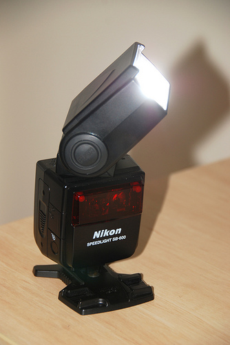
Check the rotation thoroughly before you put any batteries in it. It should now rotate 180° counter-clockwise and about 135° clockwise. The only thing it's missing is the detent to let you know you've arrived.
Stick your batteries in and see how it goes.
Any questions or suggestions lemme know. I've got another SB-600 to modify so I'll see if I can simplify the procedure. Good luck and have fun.
Stick your batteries in and see how it goes.
Any questions or suggestions lemme know. I've got another SB-600 to modify so I'll see if I can simplify the procedure. Good luck and have fun.