Modified Wall Clock With Pomodoro Timer
by Rocky Mountain Maker in Circuits > Clocks
1382 Views, 13 Favorites, 0 Comments
Modified Wall Clock With Pomodoro Timer

)


This Instructable is in loving memory of my Grandpa, D.E.E. He was an inspiring lifelong inventor and maker.
Introduction
I often break work into manageable intervals using the Pomodoro Technique.
What this means is that I work at something for 25 minutes and then take a break. It keeps me fresh.
I decided to modify my wall clock to count time in these 25 minute chunks (or pomodoros) and to flash when the time is up.
I'll let you in on a secret - when there's something I don't want to do, I set this pomodoro countdown clock running. I like it because I can see what time I will be free of the chore (the last light), and it keeps me focussed on the task at hand while the countdown is happening, as I aim to finish the task before all of the lights turn out.
How it works:
A bbc micro:bit v2 mounted in the clock, receives an input from a bbc micro:bit v2 sat on my desktop. When I want to start the pomodoro, I 'tell' the clock where the minute hand is, and it lights up the LEDs on the clock face for the next 25 minutes. As the time passes, the LEDs turn off one by one, until the pomodoro is complete. At this point, all lights on the clock flash. Pomodoro done!
This clock also features a neat 'extra minutes' function, see the video above for a full explanation of what this does and how it works.
Supplies
A suitable wall clock (Important: before you buy a clock, see step one and two below to help you choose a suitable one)
Soldering Iron
Solder
Sleeveless Copper Wire (regular wire can also be used if sleeve stripped by assembler)
Wire x 2 metres
Scissors
Wire Stripper
Hot Glue Gun
Glue Sticks
Small Screwdrivers (typically used for glasses)
Electric Drill
LEDs x 12 (I used super bright LEDs, but for a more energy efficient clock use regular red or green LEDs)
BBC Microbit v2 x 2 (One is a sender and sits on your desktop, the other is a receiver mounted in the clock)
Resistors x 12 (3000 Ohms x 12 for super bright LEDs or 200 Ohms x 12 for regular red or green LEDS)
USB cable with USB A on one end (the other end is removed)
Micro:bit Battery Box (takes 2 x AAA batteries) - Note: this part is essential even if you plan to use an external USB battery pack to power the clock. This micro:bit battery box is modified in step 18 to accommodate the USB battery pack.
USB battery pack
NOTE: in this project, the USB port on the micro:bit is left free and NOT used for power. By leaving this free, the ROM can be flashed at anytime during construction, and updated once the clock is finished.
Choosing a Suitable Clock - the Back


.jpeg)

.jpeg)
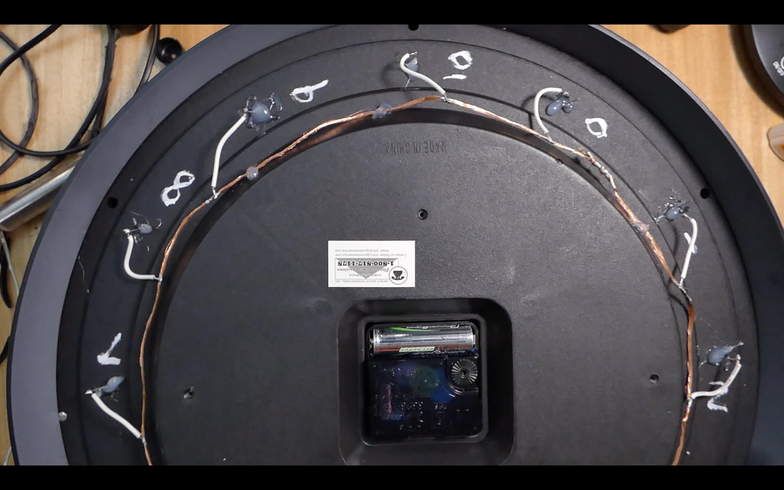
Here you can see the clock I used, from behind. For your project, the most important thing to do is to choose a clock like this, which has a good amount of hollow space behind the numbers. This is where all the electronics, and the microbit are mounted.
When viewing the clock from the side, there must be enough room for everything to sink below the back brim of the clock (the surface that touches the wall) so that the clock will sit flush on the wall when hung.
Choosing a Suitable Clock - the Clock Face

.jpeg)

Look for a clock that has an obvious place to mount the LEDs (small lights) on the clock face. On my clock, there were little triangles above each of the numbers that are a perfect size to fit the LEDs into.
Dismantle the Clock


Turn over your clock and remove the screws that hold it all together. These will probably just be around the edge of the clock (as shown), you shouldn't need to dismantle the clock mechanism in the middle of the clock.
Drill Holes for the LEDs


With the clock dismantled and the glass removed, drill a hole next to each number on the clock face, for the LED legs. You may want to start with a small drill bit, and then rebore the hole with larger drill bits until the legs of the LED poke through the clock face. The bulbous head of the LED does not go through the hole, just the legs (as pictured from behind, do not glue in place yet).
Check the Clock's Hands Clear the LEDs

With the LEDs held in place by hand on the clock face (pull on the legs from the back), check that the clock hands pass over them without getting stuck. If they cannot, adjust the LEDs so that they can.
Fix the LEDs in Place


On the back of the clock, glue in between the legs of the LEDs. This both fixes the LEDs in place, and prevents the legs touching - the glue acts as an insulator between the anode and cathode terminals of the LED.
Put the Clock Back Together

With all the LEDs in place, refit the glass and then rebuild the clock by refitting all of the screws that we removed in step 3.
Write These Numbers on the Back of the Clock

.png)
Copying this sketch, write the number "3" behind 12 o'clock, "16" behind 11 o'clock, "12" behind 10 o'clock, and so on.
Why this is important:
The micro:bit has what looks like a set of gold teeth along its bottom edge. These are GPIO (general purpose input output) pins that we will connect to the LEDs around the clock face. Each LED needs to be connected to a specific GPIO pin on the micro:bit. For now, looking at the clock from behind, write the following numbers next to each LED - you'll thank me later :) NOTE, IN FUTURE STEPS, IGNORE WHERE I HAVE WRITTEN THE NUMBERS ON MY CLOCK, THEY ARE INCORRECT. THIS SKETCH (ABOVE) IS CORRECT.
Fit the Ground Wire


.jpeg)
On the back of the clock, run a copper wire past all of the LEDs and connect it to itself, as a loop. I fitted my wire to the side of the inner plastic circle of the clock (as shown). This circular wire will connect to all of the LEDs short (negative) legs.
Secure the Ground Wire in Place With Hot Glue

Add a hot glue to a few places on the wire, to hold it in place. When looking at the clock from the side, make sure the wire does not protrude above the side of the clock (i.e. make sure the clock could still mount to the wall. The clock needs to sit flush to the wall and so nothing should be 'sticking up' out of the back of the clock that could prevent this)
Connect the LEDs' Negatives


Prepare a batch of 12 small wires. For each LED, solder one of these wires to its short leg, and the other to the ground wire.
Check That All of the LEDs Light

.jpeg)
Power the micro:bit with the USB battery pack. Connect the GND terminal on the microbit to the copper ground wire just installed. Then, connect the 3V pin on the micro:bit to each of the longer legs on the LEDs, one at a time, working your way around the clock. Check all LEDs light. If any do not, check the connection to the ground wire, and if this is solid, try replacing the LED.
Get Your Resistors Together

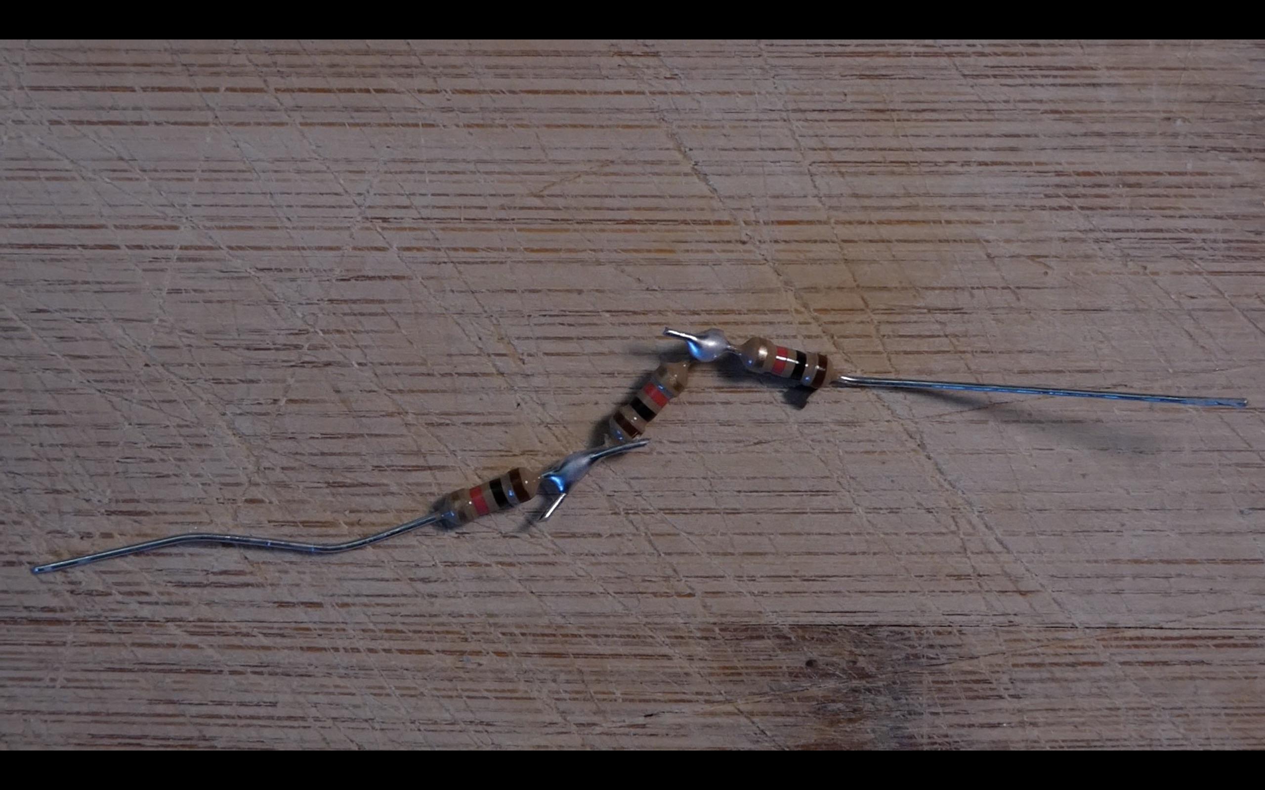

For my project, I used super bright LEDs, and I wanted to limit their ability to draw too much current. I only had 1000 Ohm resistors to hand, and so I connected three of them in series to create 3000 Ohms of resistance for each LED. If you are using regular (red / green) LEDs, skip this step, and put your resistors to one side for later - you may only need a total of 12 x 200 Ohm resistors for each LED. If you trim down the legs on the resistors when connecting them together (as I did), put the discarded legs safely to one side for later (step 15).
Test Fit the Micro:bit Into the Back of the Clock


Without fixing it in place, take the micro:bit and try to find a space where it can fit into the clock, and not protrude from the back (preventing the clock mounting to the wall). This photo from the side shows my micro:bit sitting below the brim of the back of the clock. In an ideal world, you will have enough space to mount your micro:bit within a breakout board (two of them are shown in the shot with the jiffy bag). In my case, there was not room to fit the device when it was slotted into a (convenient) breakout board.
Finishing Up With the Micro:bit


If you cannot fit the micro:bit and breakout board into the clock, you will need to solder 'legs' directly to the pins on the micro:bit (as I did). I used the legs I'd trimmed from the resistors in step 13. First, I tinned the gold edge connector on the micro:bit, being careful not to bridge any of the GPIO pins (Bridging easily happens, so keep testing that adjacent pins are not bridged together by using a multimeter in diode mode (pictured)). Next, I lightly tinned the legs, held them in place over each GPIO pin, and touched them lightly with the soldering iron to bond them to the micro:bit.
If you can fit the micro:bit within a breakout board, your life will be a lot easier!
Fit the Micro:bit Into the Back of the Clock

Cover the ground wire with electrical tape wherever it's exposed (pictured). Then secure the micro:bit in place using hot glue (pictured).
Connect the GPIO Pins to the LEDs


IF YOU DON'T HAVE THE MICRO:BIT IN A BREAKOUT BOARD
Referring to this pin chart for the micro:bit v2, connect each respective GPIO output pin to its respective LED. Solder a wire from the GPIO pin leg, to a resistor and then on to the long leg on its LED. Refer to the numbers you wrote on the clock in step 8. For example, the long leg on the LED marked '3' (at the top of the clock, specifically at 12 o'clock), should be soldered to GPIO pin 3 on the micro:bit, via a resistor. The LED marked '16' should be soldered to GPIO pin 16, and so on. Don't forget to add the resistor for each LED (200 Ohms for red/green LEDs, 3000 Ohms for super bright LEDs). If you are using a micro:bit v1, Google the pin outs for that rather than using this chart.
IF YOU HAVE THE MICRO:BIT IN A BREAKOUT BOARD
Follow the instructions above but instead of soldering the connections, you may be able to use easy and convenient jumper leads to make the connections to the LEDs. The resistors may still need soldering to the long legs on the LEDs.
Fit the Battery


Because I'm using super bright LEDs, my clock requires a powerful external USB battery (pictured in the photo with the lighted clock face). This sits on a shelf below the clock, and I run a wire to it from the clock. The benefit of this is that I can easily turn the micro:bit on / off at the battery without having to touch or disturb the wall-mounted clock. If you are using an external battery, fit the micro:bit battery box still - plugging it into the micro:bit, and then snip the wires for later connection to the external USB battery.
If you are using regular red/green LEDs, mount the official micro:bit battery box (for 2 x AAA batteries) into the back of the clock (pictured). Connect it to the micro:bit before mounting it, to confirm that the wires reach. If you use this battery box, consider installing an easily accessible on/off switch on the side of the clock (fit this into the negative wire of the battery box) so that the batteries can be preserved when the clock is not in use.
Drill a Hole for the Battery Wire (external USB Battery Only)
.jpeg)

Exactly beneath 6 o'clock, drill a hole in the clock body and pass your USB cable through into the back of the clock. This is the white wire pictured, on the left. Next, strip this wire and solder it to the snipped "battery box" wire leading into the micro:bit (pictured on the right). Once soldered, insulate these connections with electrical tape so they cannot touch together.
Flash This Code to the Micro:bit in the Clock
I used the online microbit.org editor for this step.
Paste the following code into the editor and then download the generated .hex file and transfer it to your micro:bit:
# Wall Clock With Pomodoro Timer (clock code) by Rocky Mountain Maker, December 2023 -> 2nd Jan 2024
# Imports go at the top
from microbit import *


import radio
import random #used to select a final clock animation


secondselapsed = 0


finalanimationset = False


animationtoshow = 2


lightson = [0,0,0,0,0,0,0,0,0,0,0,0] #stores the light states


display.off() #allows all GPIO pins to be used


ledone = 20


setupcomplete = False


startingpoint = 12


timetoshow = '' #an empty string, until something is received


nolightyet = True


incoming = 0


turnoff = 0


sleepytime = 85 #the pause time between frames, in LED animation


def animatebackwards():
    #rock around the clock
    #pin3, 4, 6, 7, 8, 9, 10, 0, 14, 13, 12, 16 - counting backwards
    pin3.write_digital(1)
    sleep(sleepytime)
    pin3.write_digital(0)
    pin4.write_digital(1)
    sleep(sleepytime)
    pin4.write_digital(0)
    pin6.write_digital(1)
    sleep(sleepytime)
    pin6.write_digital(0)
    pin7.write_digital(1)
    sleep(sleepytime)
    pin7.write_digital(0)
    pin8.write_digital(1)
    sleep(sleepytime)
    pin8.write_digital(0)
    pin9.write_digital(1)
    sleep(sleepytime)
    pin9.write_digital(0)
    pin10.write_digital(1)
    sleep(sleepytime)
    pin10.write_digital(0)
    pin0.write_digital(1)
    sleep(sleepytime)
    pin0.write_digital(0)
    pin14.write_digital(1)
    sleep(sleepytime)
    pin14.write_digital(0)
    pin13.write_digital(1)
    sleep(sleepytime)
    pin13.write_digital(0)
    pin12.write_digital(1)
    sleep(sleepytime)
    pin12.write_digital(0)
    pin16.write_digital(1)
    sleep(sleepytime)
    pin16.write_digital(0)


def animateforwards():
    #rock forwards around the clock


    #3, 16, 12, 13, 14, 0, 10, 9, 8, 7, 6, 4 - the actual clock face
    pin3.write_digital(1)
    sleep(sleepytime)
    pin3.write_digital(0)
    pin16.write_digital(1)
    sleep(sleepytime)
    pin16.write_digital(0)
    pin12.write_digital(1)
    sleep(sleepytime)
    pin12.write_digital(0)
    pin13.write_digital(1)
    sleep(sleepytime)
    pin13.write_digital(0)
    pin14.write_digital(1)
    sleep(sleepytime)
    pin14.write_digital(0)
    pin0.write_digital(1)
    sleep(sleepytime)
    pin0.write_digital(0)
    pin10.write_digital(1)
    sleep(sleepytime)
    pin10.write_digital(0)
    pin9.write_digital(1)
    sleep(sleepytime)
    pin9.write_digital(0)
    pin8.write_digital(1)
    sleep(sleepytime)
    pin8.write_digital(0)
    pin7.write_digital(1)
    sleep(sleepytime)
    pin7.write_digital(0)
    pin6.write_digital(1)
    sleep(sleepytime)
    pin6.write_digital(0)
    pin4.write_digital(1)
    sleep(sleepytime)
    pin4.write_digital(0)


def animatealternating():
    global lightson #this global definition allows me to APPEND to the global
    #list, it's no needed if you are just reading from a global variable

    lightson = [0,1,0,1,0,1,0,1,0,1,0,1] #light animation frame 1
    updatelights()
    sleep(500)
    lightson = [1,0,1,0,1,0,1,0,1,0,1,0] #light animation frame 2
    updatelights()
    sleep(500)


def updatelights():
    #global lightson #using global here allows me to APPEND to the global variable
    #this would not be needed if I was just referencing a global variable

    pin3.write_digital(lightson[0]) #no. 12
    pin16.write_digital(lightson[1]) #no. 1
    pin12.write_digital(lightson[2]) #no. 2
    pin13.write_digital(lightson[3]) #no. 3
    pin14.write_digital(lightson[4]) #no. 4
    pin0.write_digital(lightson[5]) #no. 5
    pin10.write_digital(lightson[6]) #no. 6
    pin9.write_digital(lightson[7]) #no. 7
    pin8.write_digital(lightson[8]) #no. 8
    pin7.write_digital(lightson[9]) #no. 9
    pin6.write_digital(lightson[10]) #no. 10
    pin4.write_digital(lightson[11]) #no. 11

    #3, 16, 12, 13, 14, 0, 10, 9, 8, 7, 6, 4 - the clock face


while True:


    incoming = radio.receive()

    timetoshow = str(incoming)

    if timetoshow == 'reset': #later in the code too, into the animation for loop
        reset()

    if timetoshow[0:3] == '12a':
        lightson = [1,1,1,1,1,1,0,0,0,0,0,0] #runs from 0 to 5
        startingpoint = 0
        updatelights()
    elif timetoshow[0:3] == '1aa':
        lightson = [0,1,1,1,1,1,1,0,0,0,0,0] #runs from 1 to 6
        startingpoint = 1
        updatelights()
    elif timetoshow[0:3] == '2aa':
        lightson = [0,0,1,1,1,1,1,1,0,0,0,0] #runs from 2 to 7
        startingpoint = 2
        updatelights()
    elif timetoshow[0:3] == '3aa':
        lightson = [0,0,0,1,1,1,1,1,1,0,0,0] #runs from 3 to 8
        startingpoint = 3
        updatelights()
    elif timetoshow[0:3] == '4aa':
        lightson = [0,0,0,0,1,1,1,1,1,1,0,0] #runs from 4 to 9
        startingpoint = 4
        updatelights()
    elif timetoshow[0:3] == '5aa':
        lightson = [0,0,0,0,0,1,1,1,1,1,1,0] #runs from 5 to 10
        startingpoint = 5
        updatelights()
    elif timetoshow[0:3] == '6aa':
        lightson = [0,0,0,0,0,0,1,1,1,1,1,1] #runs from 6 to 11
        startingpoint = 6
        updatelights()
    elif timetoshow[0:3] == '7aa':
        lightson = [1,0,0,0,0,0,0,1,1,1,1,1] #rule change - runs from 7 to 0 (see 12 as 0)
        startingpoint = 7
        updatelights()
    elif timetoshow[0:3] == '8aa':
        lightson = [1,1,0,0,0,0,0,0,1,1,1,1] #8 to 1
        startingpoint = 8
        updatelights()
    elif timetoshow[0:3] == '9aa':
        lightson = [1,1,1,0,0,0,0,0,0,1,1,1] #9 to 2
        startingpoint = 9
        updatelights()
    elif timetoshow[0:3] == '10a':
        lightson = [1,1,1,1,0,0,0,0,0,0,1,1] #10 to 3
        startingpoint = 10
        updatelights()
    elif timetoshow[0:3] == '11a':
        lightson = [1,1,1,1,1,0,0,0,0,0,0,1] #11 to 4 (including 0, obvs)
        startingpoint = 11
        updatelights()

        #read additional minutes
    if timetoshow[3:4] == '0':
        ledone = 10 #wait a little before turning off so all 5 glow for a brief time
    elif timetoshow[3:4] == '1':
        ledone = 60
    elif timetoshow[3:4] == '2':
        ledone = 120
    elif timetoshow[3:4] == '3':
        ledone = 180
    elif timetoshow[3:4] == '4':
        ledone = 240
    elif timetoshow[3:4] == '5': #probably not needed but can be used for a 30 min pomo
        ledone = 300


    #CHECK LIGHTSON HERE FOR 1, IF SO, DATA HAS BEEN RECEIVED, SO make setup complete TRUE
    checkforoneinarray = str(lightson)
    if '1' in checkforoneinarray:
        setupcomplete = True

    #then lightup the clock as needed, calling the pins in chronological order and
    #feeding the 'lightson' array


    if setupcomplete == True:


        if secondselapsed == ledone:

            turnoff = startingpoint #this is always in range because it's defined 0 - 12 above


            lightson[turnoff] = 0
            updatelights()

        elif secondselapsed == ledone + 300: #300 = 5 minutes later

            turnoff = startingpoint + 1 #change the next item in the array
            if turnoff > 11:
                turnoff = turnoff - 12 #so it doesnt reference outside of the array, instead returning to the beginning

            lightson[turnoff] = 0
            updatelights()

        elif secondselapsed == ledone + 600: #600 = 10 minutes later
            turnoff = startingpoint + 2 #change the next item in the array...

            if turnoff > 11:
                turnoff = turnoff - 12 #so it doesnt reference outside of the array, instead returning to the beginning

            lightson[turnoff] = 0 #...to 0
            updatelights()

        elif secondselapsed == ledone + 900: #900 = 15 minutes later
            turnoff = startingpoint + 3 #change the next item in the array...

            if turnoff > 11:
                turnoff = turnoff - 12 #so it doesnt reference outside of the array, instead returning to the beginning

            lightson[turnoff] = 0 #...to 0, turning off the light the minutes hand is passing
            updatelights()

        elif secondselapsed == ledone + 1200: #1200 = 20 minutes later
            turnoff = startingpoint + 4 #change the next item in the array...

            if turnoff > 11:
                turnoff = turnoff - 12 #so it doesnt reference outside of the array, instead returning to the beginning

            lightson[turnoff] = 0 #...to 0
            updatelights()

        elif secondselapsed == ledone + 1500: #1500 = 25 minutes later
            turnoff = startingpoint + 5 #change the final item in the array...

            if turnoff > 11:
                turnoff = turnoff - 12 #so it doesnt reference outside of the array, instead returning to the beginning

            lightson[turnoff] = 0 #...to 0 - all lights now off
            updatelights()
            sleep(1000) #wait 'a second' before showing the end animation


            if finalanimationset == False:
                animationtoshow = random.randint(1, 3)
                finalanimationset = True


            for i in range(300): #show the animation for around 5 mins - each is around 1 second
                if animationtoshow == 1:
                    animateforwards()
                elif animationtoshow == 2:
                    animatealternating()
                elif animationtoshow == 3:
                    animatebackwards()
                #reset check here
                incoming = radio.receive()
                if incoming == 'reset':
                    reset()


            reset() #after 5 mins of animation, reset

            #continue in this way until reset - allowing a glance at the clock to see that the pomodoro timer is done


        sleep(993) #wait 'one second' before retriggering the loop - not 1000 bc the microbit looses count as it does other things, so 993 correlates to time as my clock counts it...
        secondselapsed = secondselapsed + 1
Flash the Clock Sender Code to Your Free Micro:bit

Your spare micro:bit will be used to send instructions to the clock, as to when a new pomodoro should start.
Copy the code below into the online Python Editor for Microbit. Generate a .hex file from this code and transfer it to your spare micro:bit (pictured here next to the clock).
# Wall Clock With Pomodoro Timer (sender code) by Rocky Mountain Maker, December 2023 -> 2nd Jan 2024
# Imports go at the top
from microbit import *


import radio


selection = 0


btnbselection = 0


messagetosend = '12'


extramins = 0


transmit = '12a0'


#controls
#a - set, b - confirm, touch logo - reset


while True:


    if pin_logo.is_touched():
        radio.send('reset')


    if btnbselection == 0: #button a selects starting point on clock
        if button_a.is_pressed():
            selection += 1
            sleep(300)

        if selection == 0:
            display.show(Image.CLOCK12)
            messagetosend = '12a'
        elif selection == 1:
            display.show(Image.CLOCK1)
            messagetosend = '1aa'
        elif selection == 2:
            display.show(Image.CLOCK2)
            messagetosend = '2aa'
        elif selection == 3:
            display.show(Image.CLOCK3)
            messagetosend = '3aa'
        elif selection == 4:
            display.show(Image.CLOCK4)
            messagetosend = '4aa'
        elif selection == 5:
            display.show(Image.CLOCK5)
            messagetosend = '5aa'
        elif selection == 6:
            display.show(Image.CLOCK6)
            messagetosend = '6aa'
        elif selection == 7:
            display.show(Image.CLOCK7)
            messagetosend = '7aa'
        elif selection == 8:
            display.show(Image.CLOCK8)
            messagetosend = '8aa'
        elif selection == 9:
            display.show(Image.CLOCK9)
            messagetosend = '9aa'
        elif selection == 10:
            display.show(Image.CLOCK10)
            messagetosend = '10a'
        elif selection == 11:
            display.show(Image.CLOCK11)
            messagetosend = '11a'
        elif selection == 12: #roll around
            selection = 0

        if button_b.is_pressed():
            btnbselection += 1
            sleep (300)


    elif btnbselection == 1:


        display.show(extramins)

        if button_a.is_pressed():
            extramins += 1
            sleep(300)
            if extramins >= 6:
                extramins = 0


        if button_b.is_pressed():
            #append the string with the extra mins
            transmit = messagetosend + str(extramins)
            display.show(Image.YES)
            radio.send(transmit)
            sleep(3000)
            display.off()
Finished!


Add your maker's mark and then the clock is ready to be hung on the wall, and used whenever you need to count time in pomodoros!