Modification of the Pantum 2502W for Direct Laser Printing of Printer Circuit Boards
by mlerman in Circuits > Tools
46878 Views, 125 Favorites, 0 Comments
Modification of the Pantum 2502W for Direct Laser Printing of Printer Circuit Boards
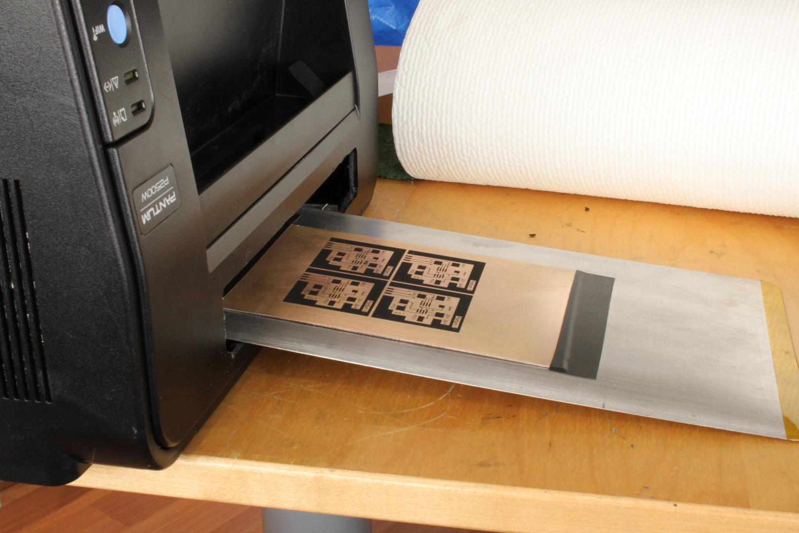
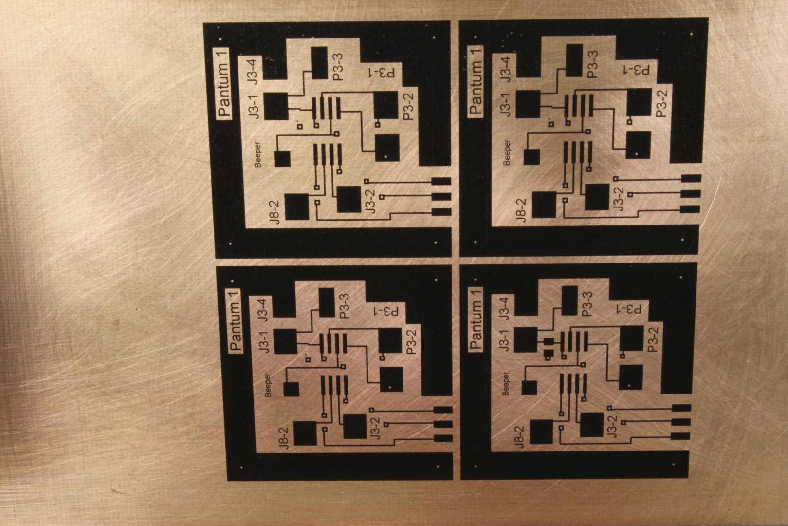
Many of you have been following my series of Instructables on repurposing a Lexmark E260 laser printer to print toner directly on copperclad boards. Once printed and "fixed" to the copper by acetone vapor, the toner acts as a resist during the normal etching process, producing a finely detailed printed circuit board (PCB). I call this process DLP for Direct Laser Printing.
A problem some of you have had in duplicating this project is sourcing E260s. While I have purchase several E260s for $45 USD, including shipping, on eBay, they usuallyare more like $70-$90 USD. Since these are used printers, usually sold without Toner or Drum, the real cost escalates to more like $175 USD. When you add in another $30-$50 for parts, the project starts to get expensive, especially if this is a hobby rather than a business.
The Pantum 2502W is a complete laser printer, including toner, for just $25 USD!! I just ordered and received two of these little printers, shipping included, no tax (!) for $24.99 USD each from Newegg, Last week I splurged and spent $29.99 for one at MicroCenter. The Pantum is also quite compact at 13.2 x 8.6 x 7 inches, and weighs in at just about 10 pounds, compared to about 30 pounds for the E260.
This Instructable details the conversion of the Pantum 2502W for Direct Laser Printing. If you have any questions, please contact me directly at mlerman@ix.netcom.com.
Parts and Tools
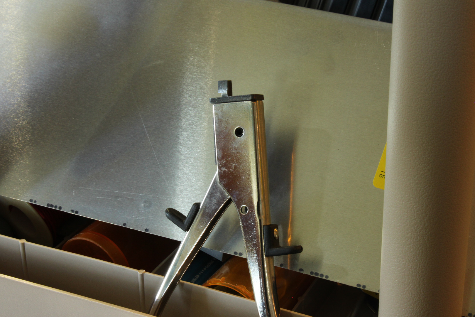
Parts
Pantum 2502W printer
MCU Board - see text.
14 inches of 6 inch wide x .020 aluminum sheet.
5 inches of 1.5 inch x 1.5 inch x .062 inch aluminum angle.
Some machine screws and nuts - 4-40, 8-32 or metric equivalent.
2 spacers, 6-32 x 1 inch long, threaded. See text
Double sided masking or other thin tape at least 1 inch wide.
Tools
Nibbling Tool - optional, see link and text
Saw to cut thin aluminum angle. A chop saw is nice, but a hacksaw will do quite nicely.
Dremel - optional but very useful.
Other common workshop tools - soldering iron, screwdrivers, drill, etc.
Unpacking and Testing the Printer
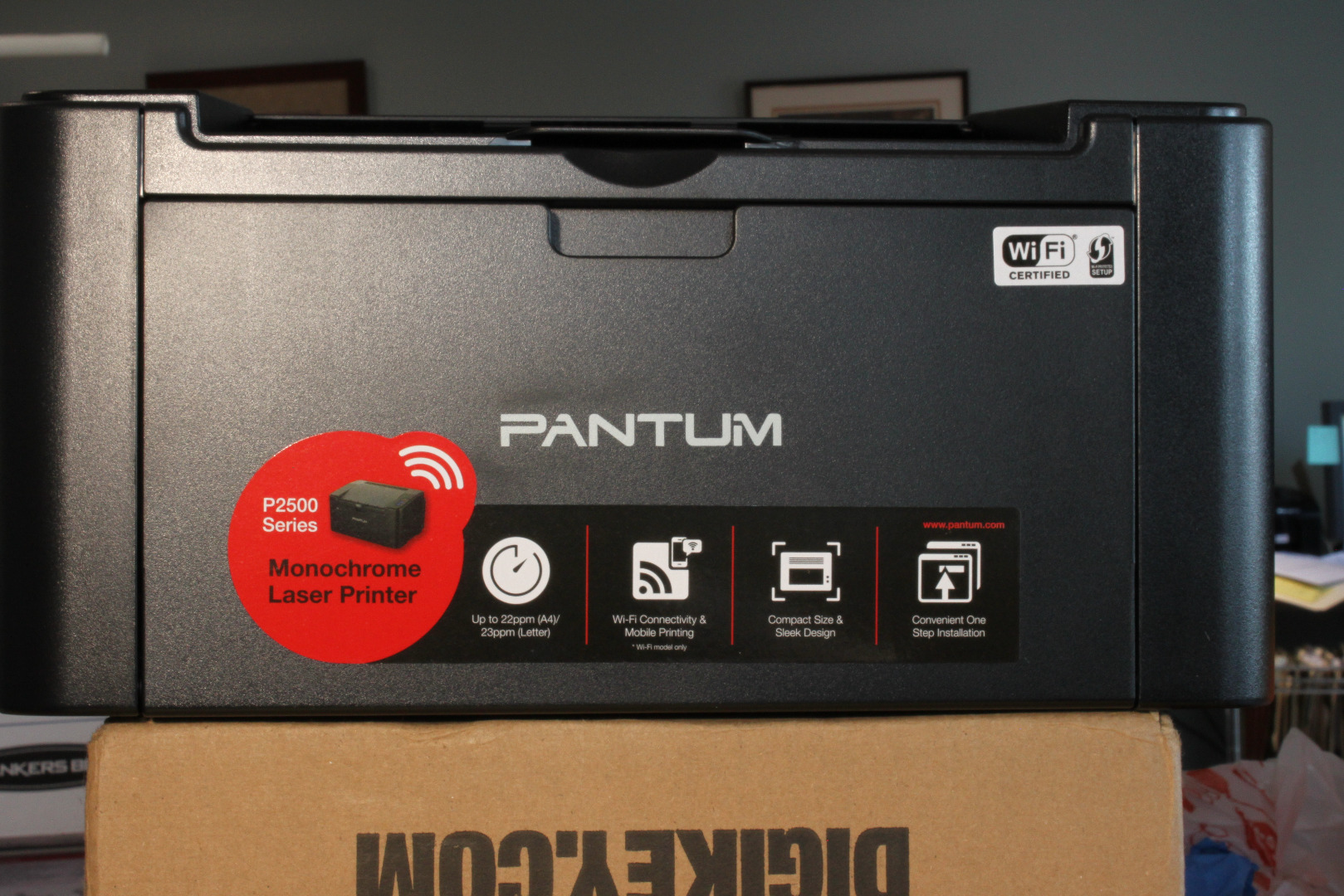
1 - Unpack the printer, removing all the packing material.
2 - Remove the Toner Cartridge, and follow the enclosed guide to unwrap it and prepare it to print. Then replace the Toner Cartridge.
2 - Install the printer on your computer as per the directions.
3 - Print a page or two to be sure everything is working correctly.
4 - The default "Sleep" setting is 1 minute, which is much too short for what we are doing. Go to Printer Properties, Secondary Settings, and set "Sleep" to 60 minutes.
5 - Turn printer off, remove and safely store Toner Cartridge in dark place.
6 - Unplug the printer and disconnect the USB cable.
Remove Some Stuff
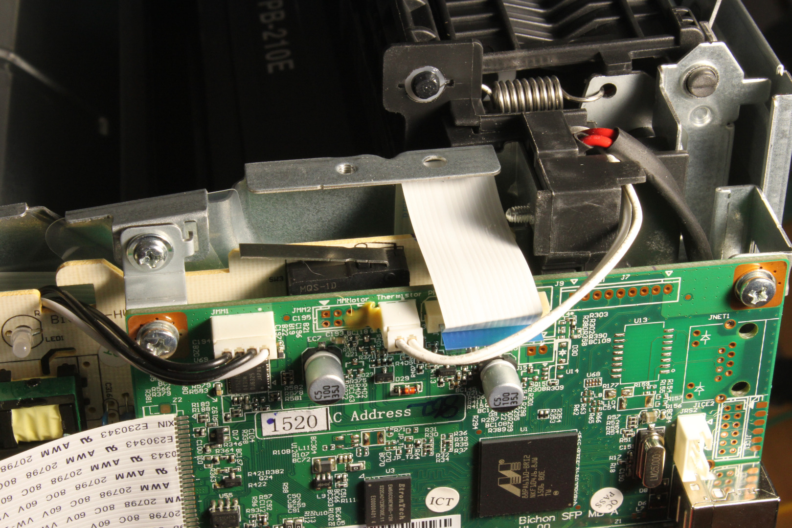
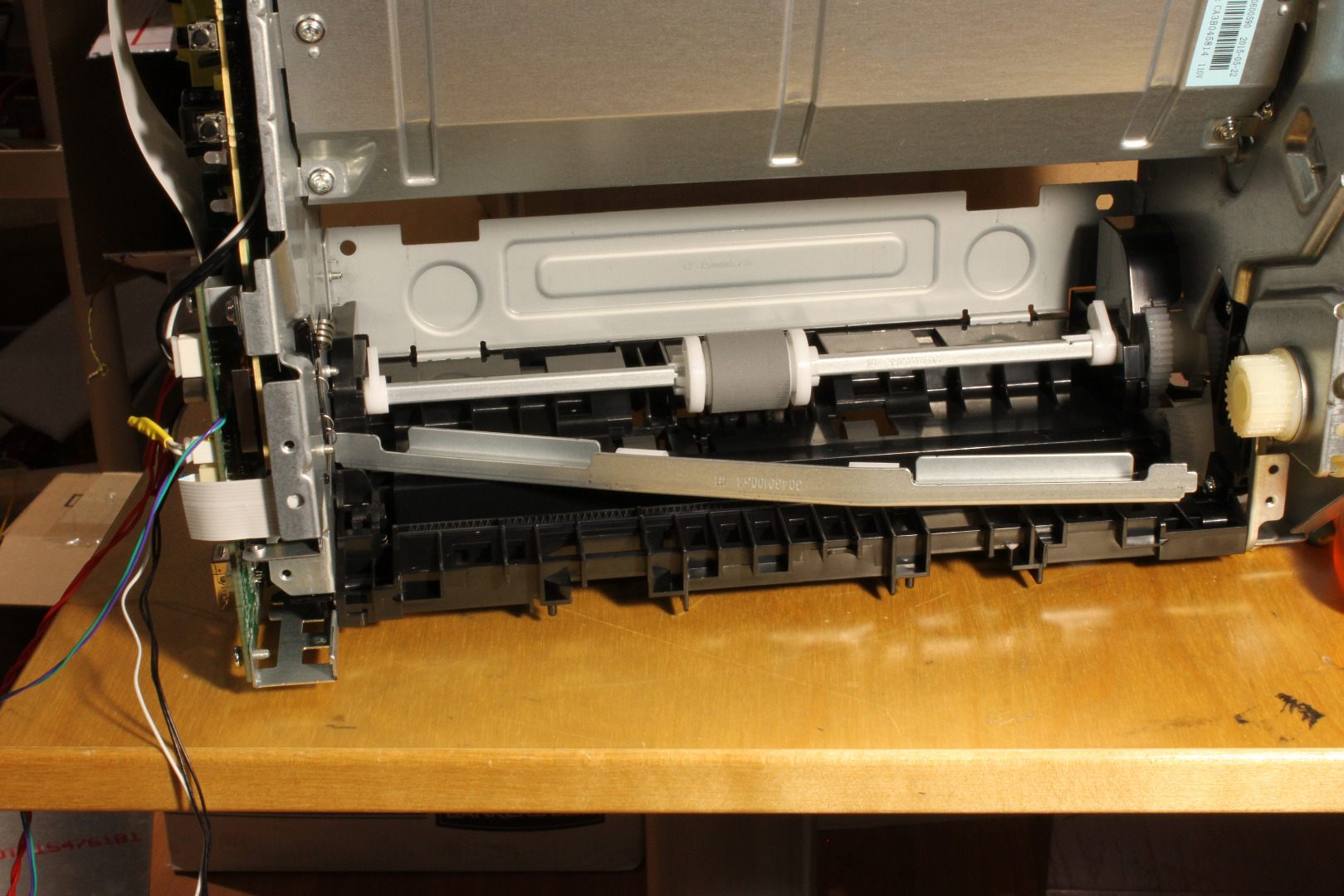
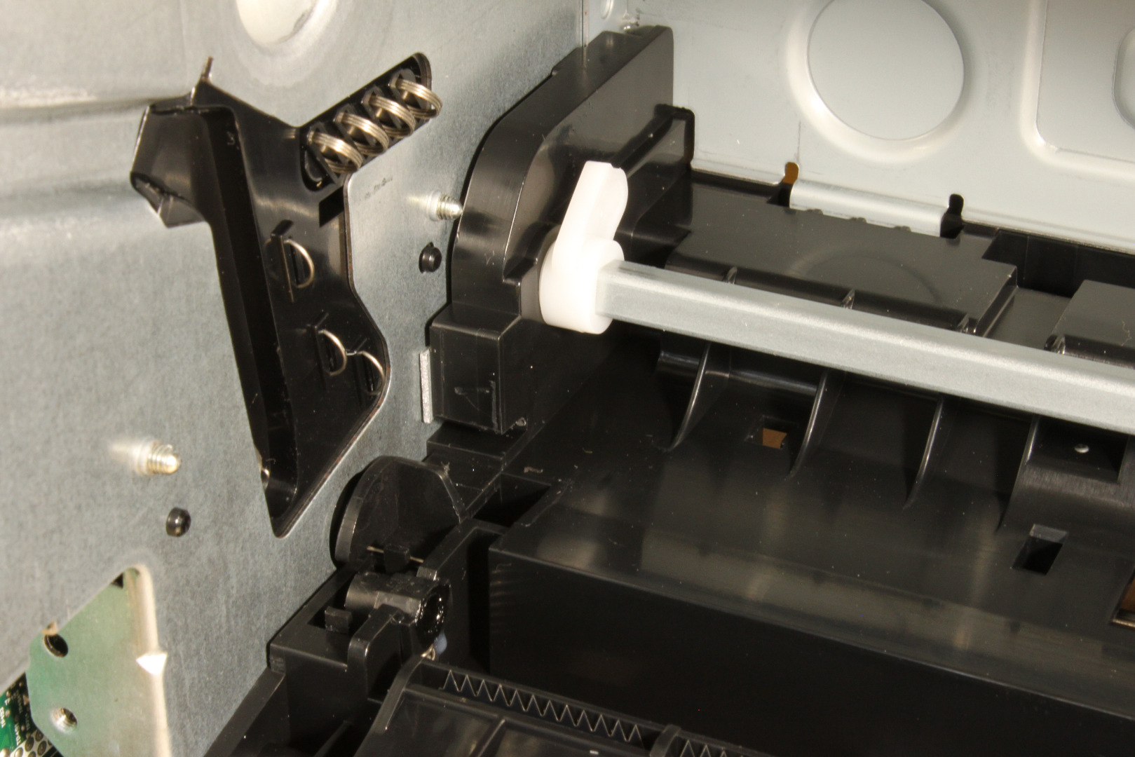
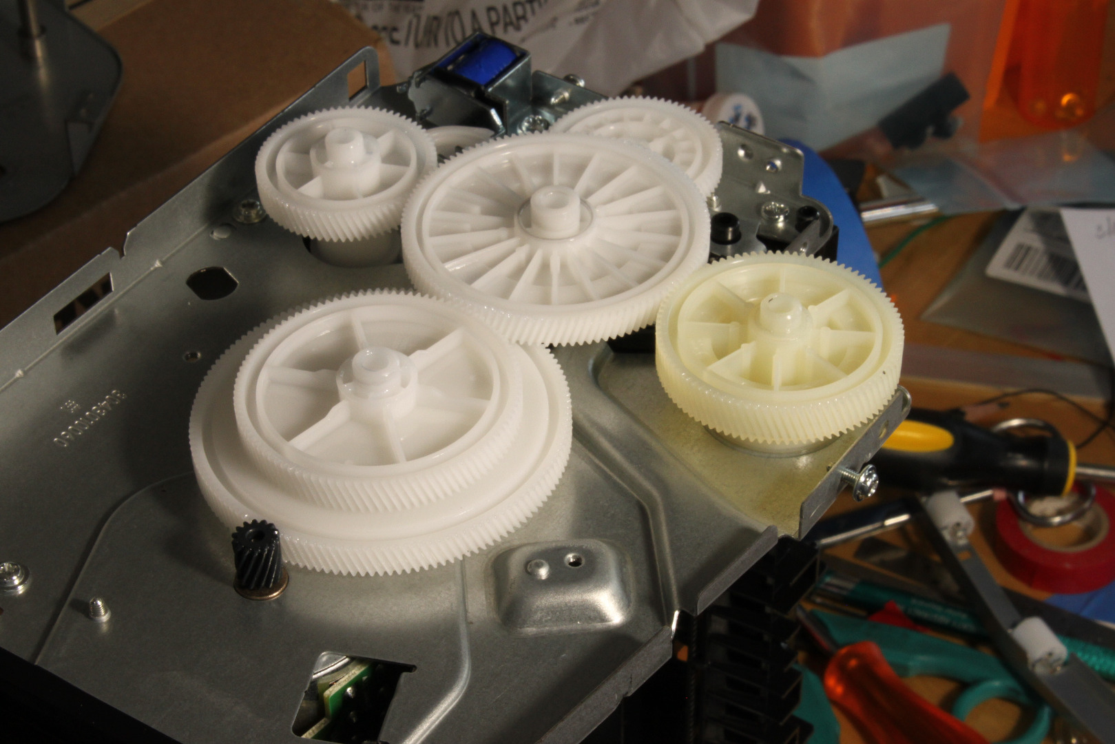
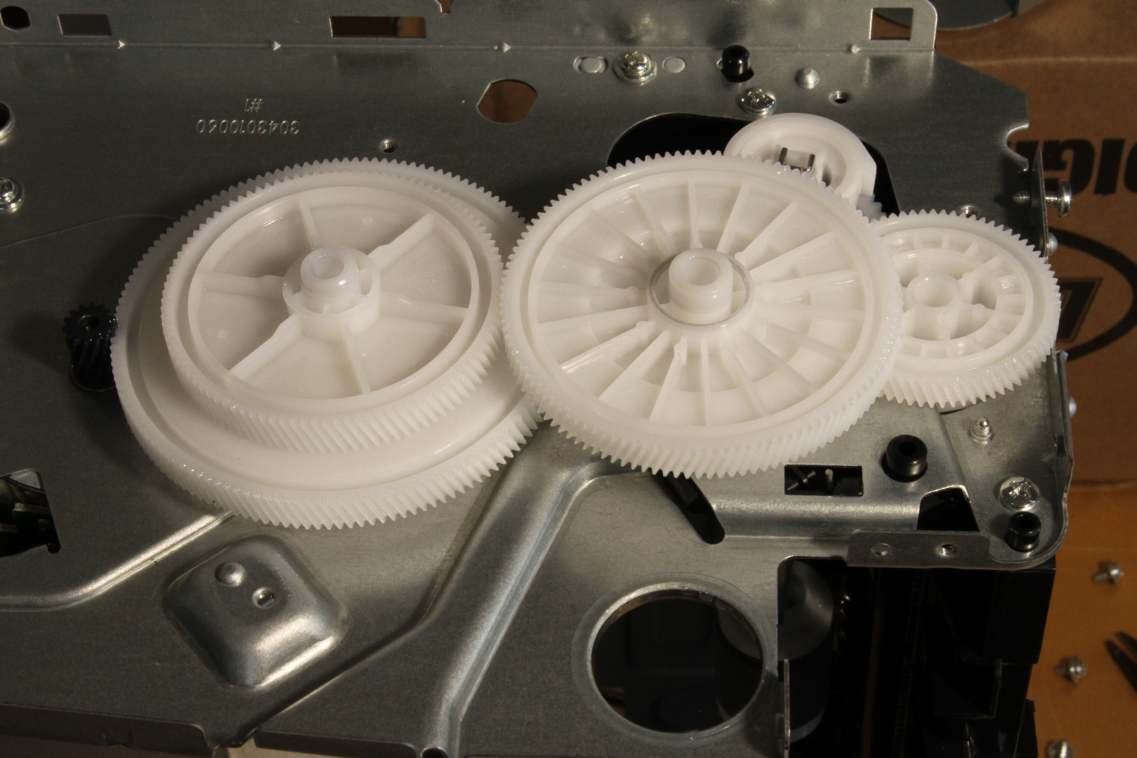
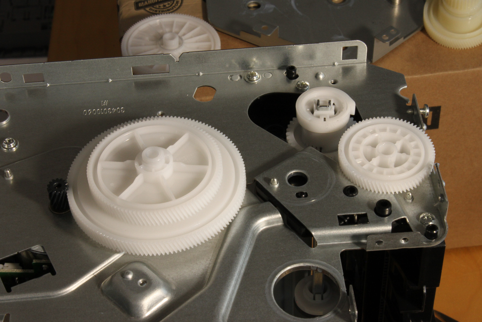
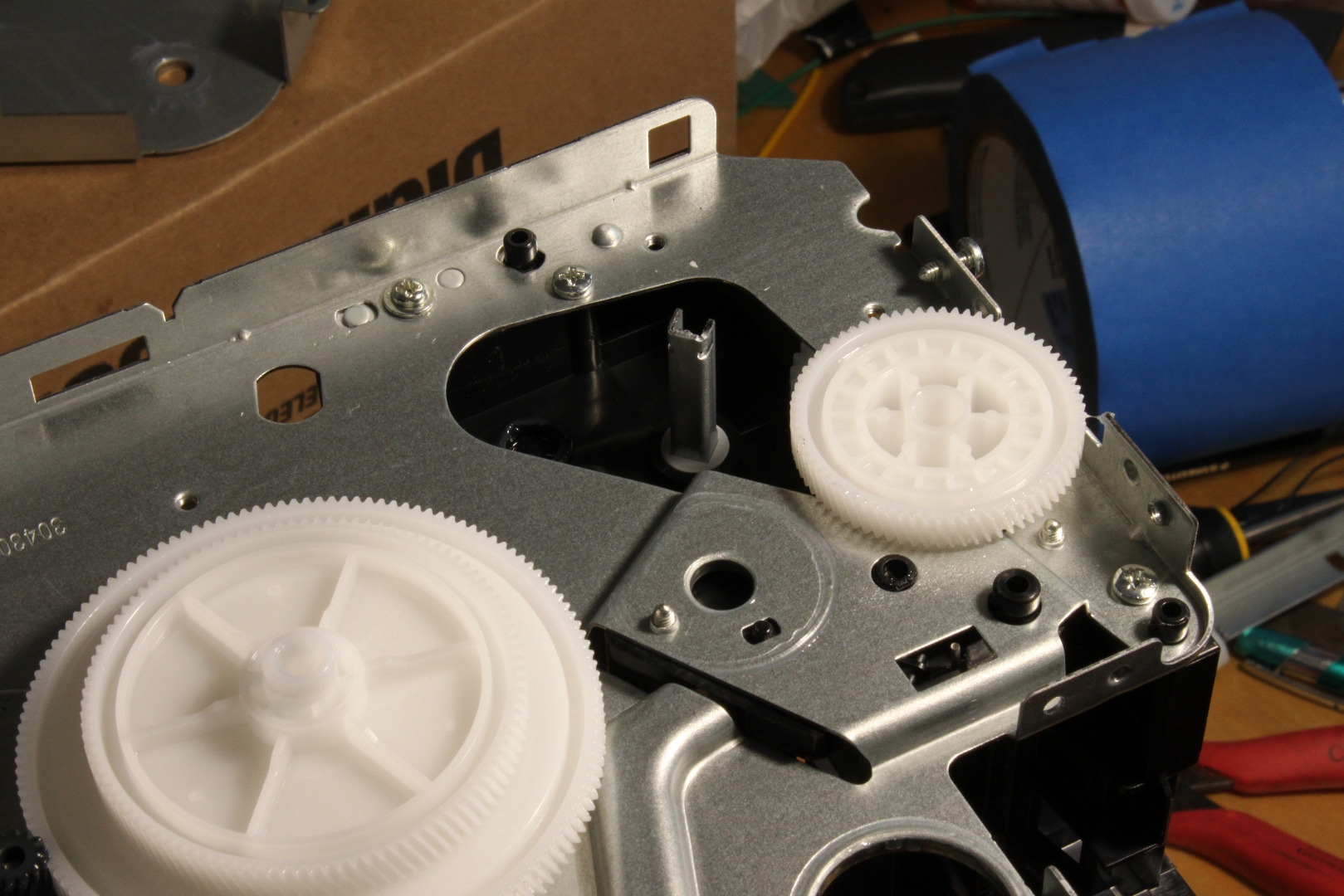
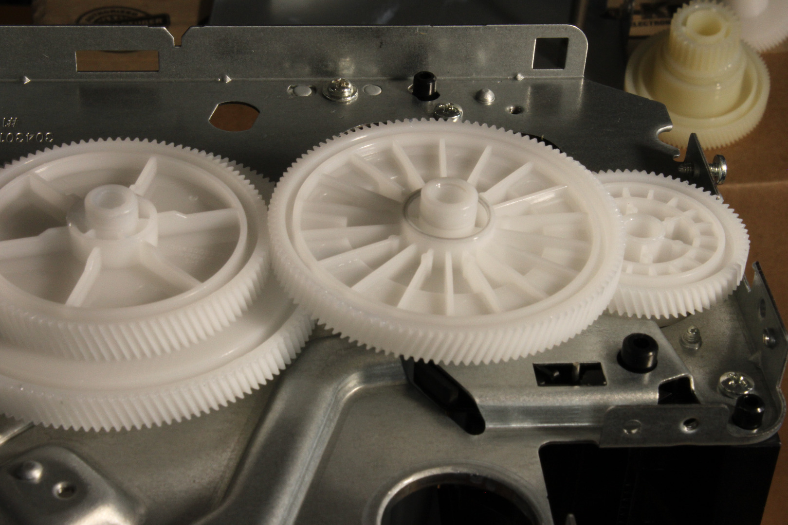
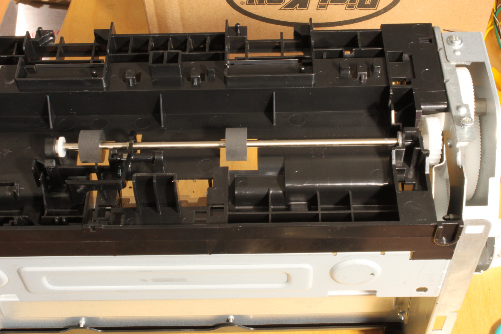
We are now going to take the printer apart a bit (actually quite a bit) and remove a bunch of parts we don't need. In my E260 Instructables I provided a comprehensive Service Manual that detailed the removal and replacement of most of the key components of the printer. Unfortunately, there seems to be no equivalent Service Manual for the Pantum 2502W, so I have included a lot more photos and descriptive text. If you run into trouble, look at the photos!
When you remove screws, but sure to note which screw came from where so that you can replace them correctly when you reassemble the printer.
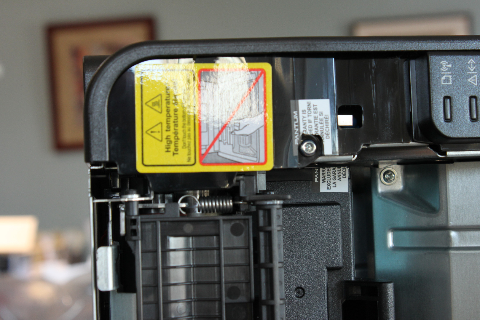
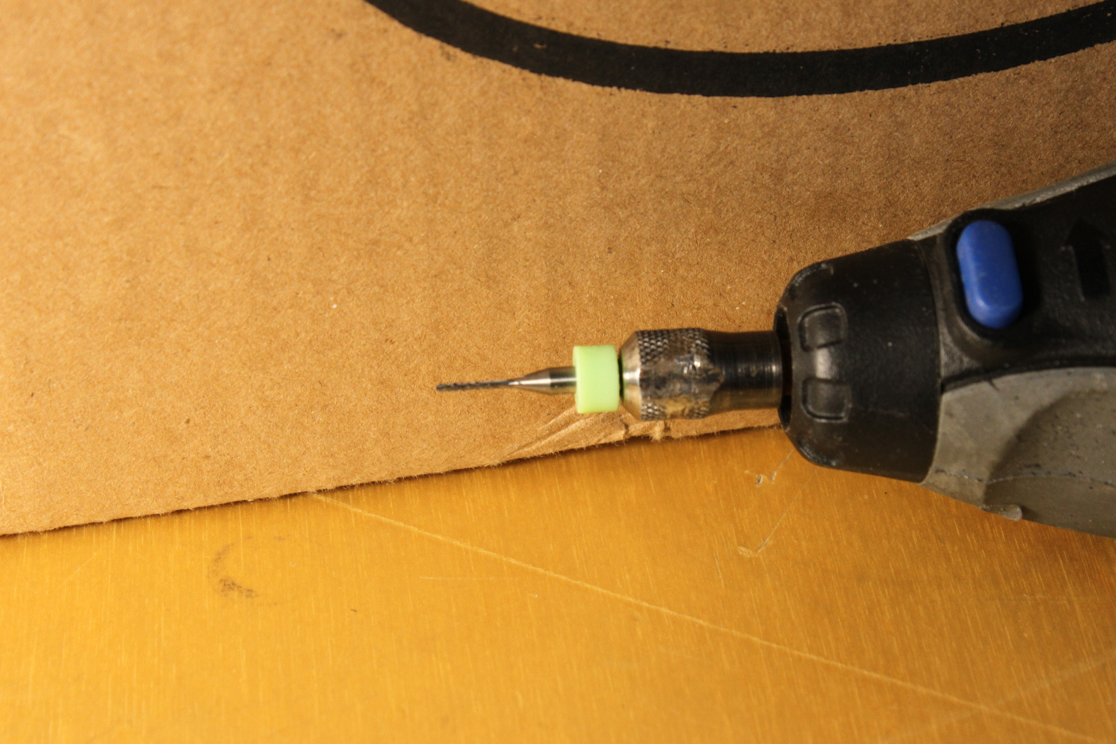
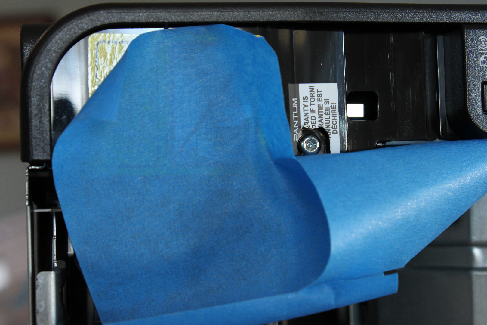
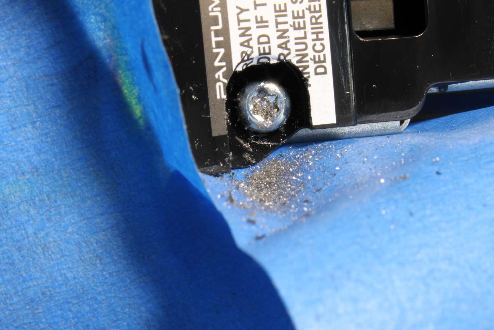
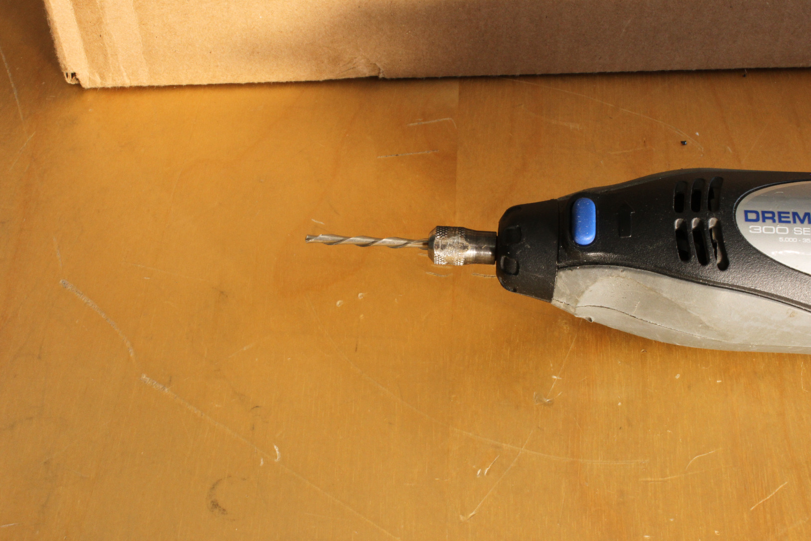
Remove screw located under black and white warning label on the top right side, just in front of the yellow warning label. This is some sort of security screw, and I have nothing that fits it, so I used a 1mm carbide mill in a Dremel to mill a rough slot in the head of the screw, then used a small screwdriver to remove it. Use tape to protect so chips don't drop into printer. This screw cannot be reused.
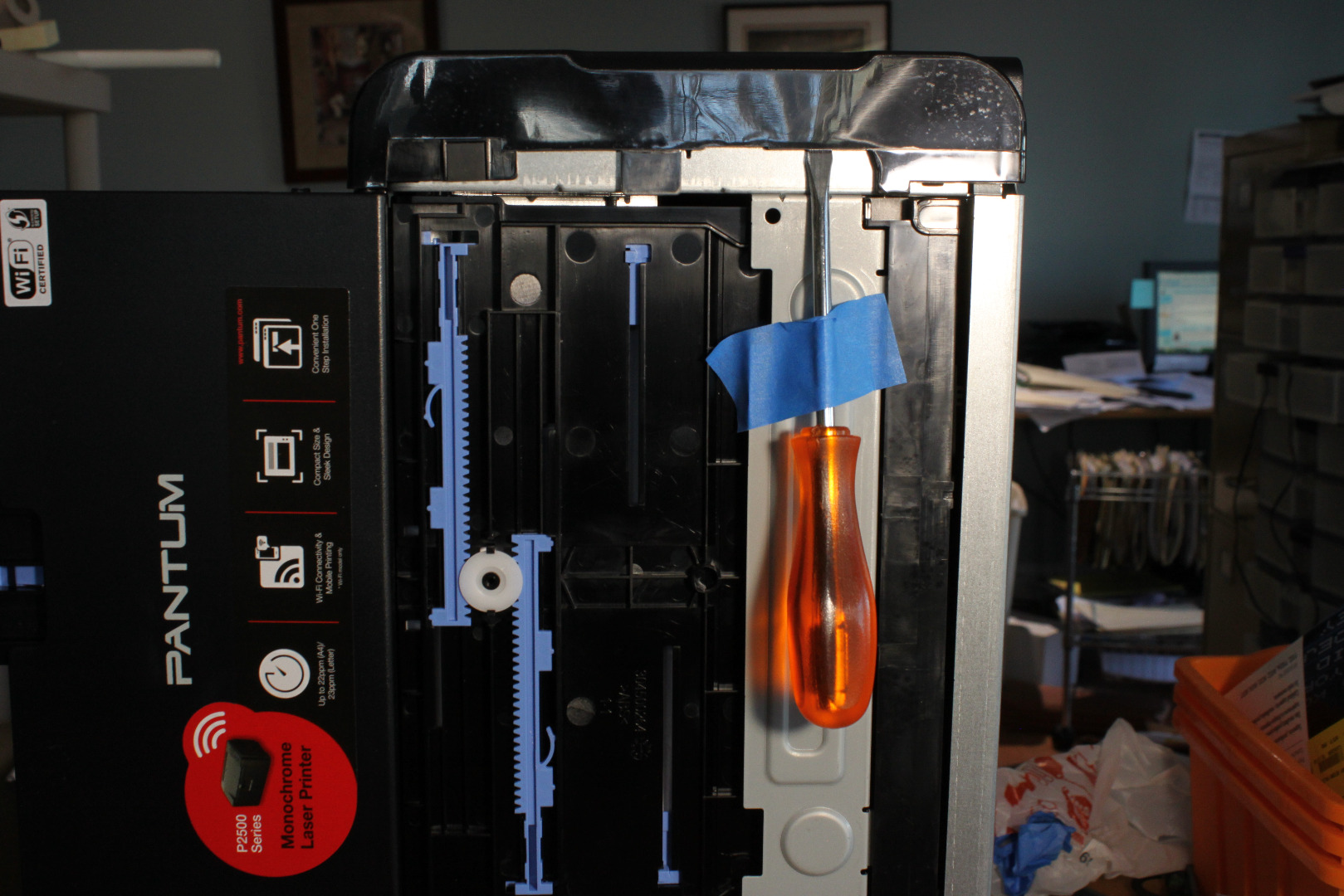
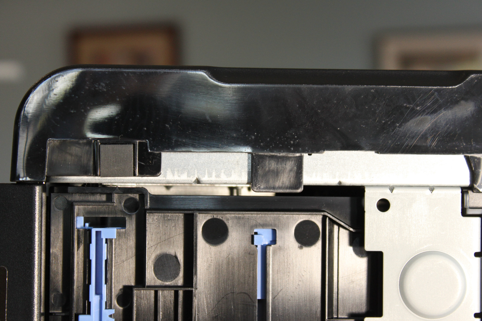
Remove the Front Paper Tray by wedging a screwdriver at the pivot between the tray and Front Panel. Save the tray to be used later.
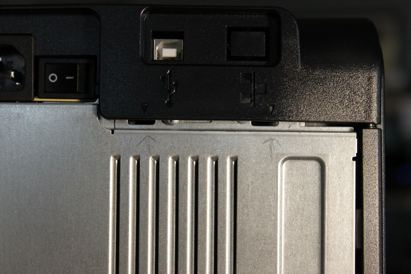
Remove the Right Side Cover. This is the side with the Operator Panel on top. Place the printer left side down, put a screwdriver blade under the edge of the cover between the embossed arrows on rear of the panel (photo), then pop the clips out of the slots. Do NOT try to completely remove the cover at this time!
Using a Screwdriver as shown on bottom of printer, gently pop the Right Side Cover off, but DO NOT pull it away from the printer because there is a wire going from the circuit board to a small pcb mounted on the inside of the cover. This small pcb is the antenna for the WiFi. Remove the antenna from its mounting clip and cut the cable near the pcb. We will not be using WiFi.
Remove the Top Cover - it should be hanging loose from the left side pivot.
Remove the Left Side Cover. First remove the screw on the top; fortunately, this screw is a simple Phillips head, not a security screw. Then slide a screwdriver blade under the edge of the cover near the arrows on the rear of the printer and pop the clips out. Use your fingers to pry up the tab near the center of the bottom of the cover and the cover will pop right off. Note what the screw looks like and save the screw.
Remove the 3 screws holding the metal Rear Cover Plate in place. Note that the top right screw, the one with the flanged head, does not need to be removed to remove the Rear Cover Plate. Save the screws. The screw at the top of the metal cover will not be used and can be used to replace the damaged security screw on the Right Side Cover.
Remove the 4 screws holding the Fuser in place and remove the entire Fuser. It is connected to the printer pcb by two cables.
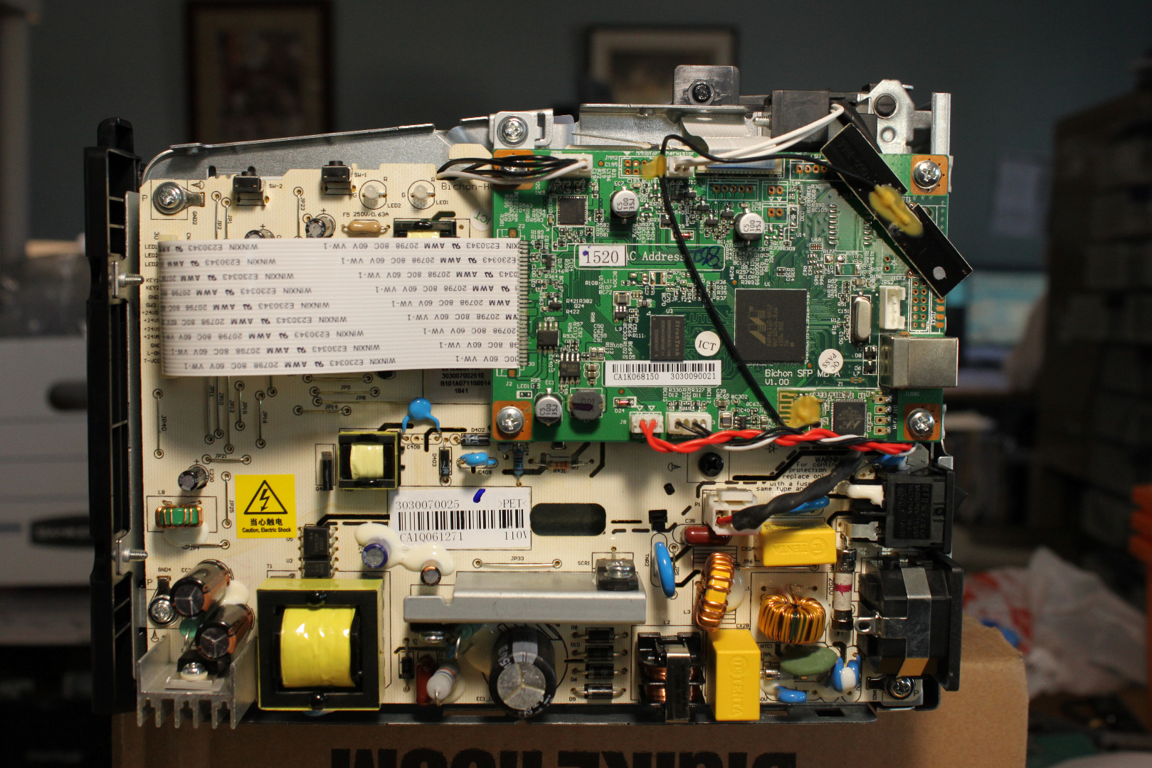
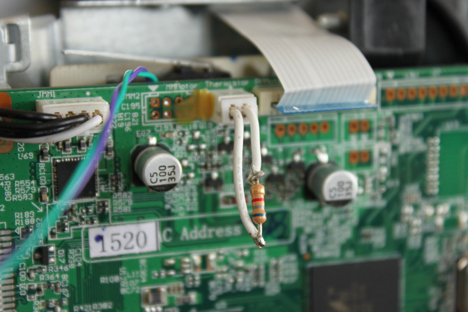
Remove the Heater connector to the Fuser. This is the large white connector just below the green pcb. Cut the cable near the Fuser. Remove the Thermistor cable at J13. It is located just to the left of the small FFC (Flex Flat Cable). Cut the two white wires up near the Fuser, leaving at least one inch of wire connected to the cable. The Thermistor itself is located in the Fuser assembly. Its job is to measure the temperature of the Fuser so that the controller can keep the Fuser hot enough to "fuse" the toner to the paper. We will not be using the Fuser, so you can discard it. But be sure to keep the Thermistor cable!
Since we will not be using the Fuser, we will need to use a resistor to "fool" the printer into thinking that the Fuser is connected and ready to go. Fortunately, the value of the resistor isn't critical and anything from 5K to 10K ohms will do - I used a 6.8K resistor. Connect the resistor across the Thermistor cable, then cover the resistor and connections with heat shrink or electrical tape and plug it back into J13.
Cut and remove the cable tie on the back of the printer. Cut the red wires near the Clutch Solenoid on
the right side, then unthread the wires from the wire guide and pull them into the Controller Enclosure.
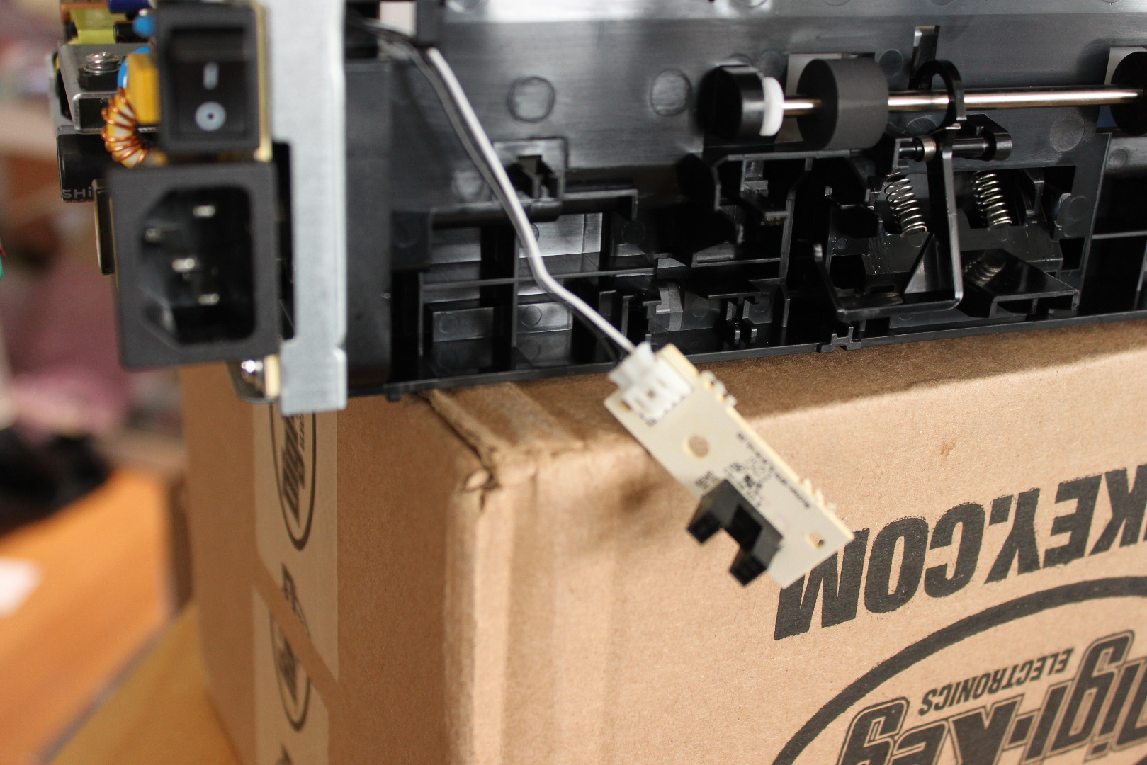
Unclip the small Sensor Board from the back of the printer, disconnect the connector, pull the cable
and connector back into the Controller Enclosure. Save the Sensor Board to be used as the NPIS later on.
Place the printer upside down. Put the tip of a flat bladed screwdriver between the bottom paper guide
and the right side of the printer, near the pivot, then pry until the pivot pops out of the hole. Do the same on the other side. Remove and discard the bottom paper guide and the springs.
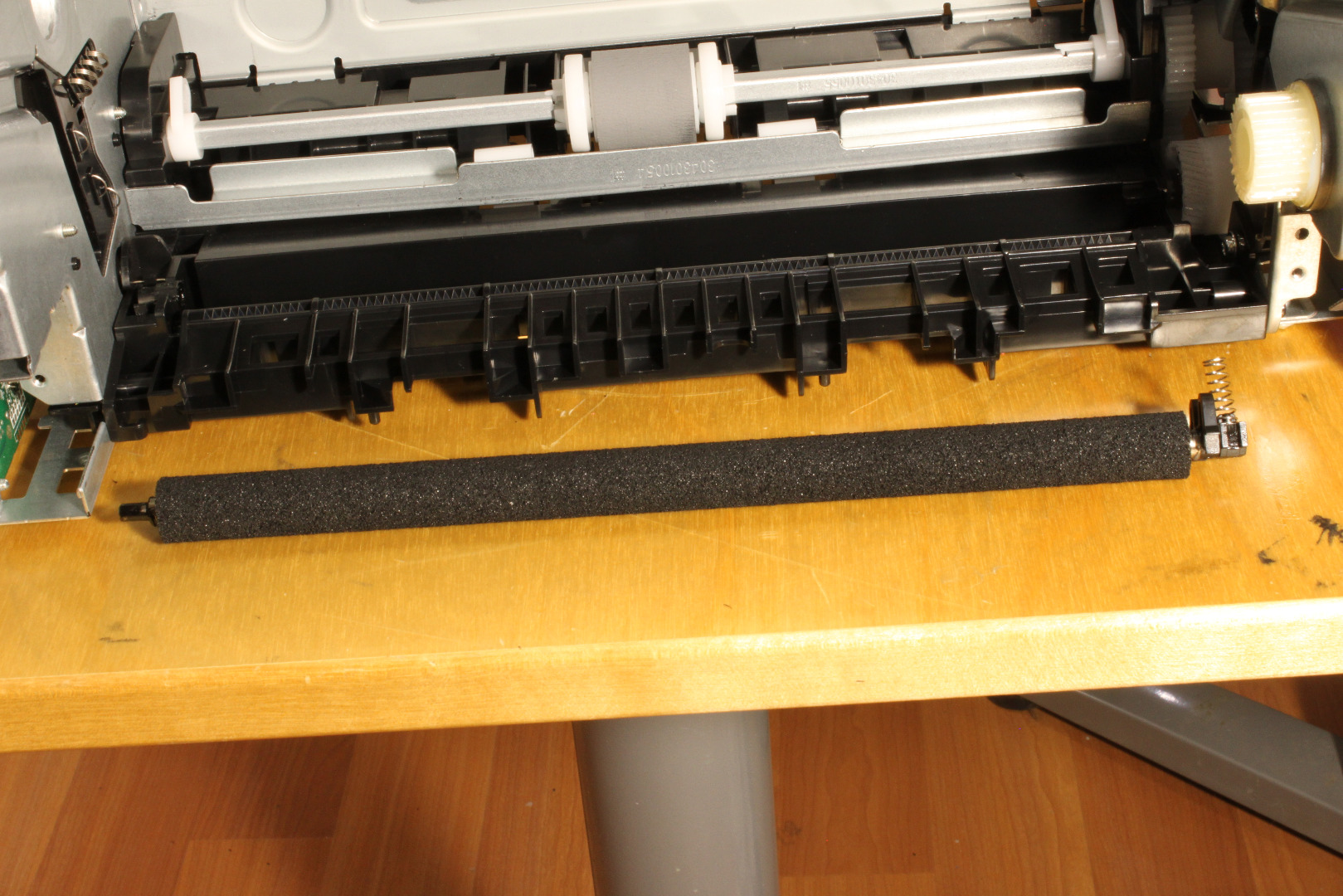
Remove the Transfer Roller by releasing the spring clips on the right side and sliding the roller out of
the left bearing. Save the Transfer Roller, Right Bearing Block and spring.
Reach in and grab the U shaped bracket with the two white rollers and pull it. The flange will pull loose from the gear side of the printer. Hold the free end and work it back and forth till the tab at the other end breaks loose. You can just leave the metal tab in place since removing it would require removing the main circuit board.
There are several ways to remove the Paper Pickup Roller and its shaft, but the cleanest way is to remove
the gearbox. Position the printer gearbox side up. Remove the 4 mounting screws, then carefully lift the coverplate off. Note where the gears go so that you can reassemble the gearbox later. See the photos.
For ease of reassembly you can remove and discard the two gears that drive the Fuser and the Paper Pickup. Remove the Clutch Solenoid (the blue thing) and discard it. Temporarily remove the large center gear so that you can easily access the paper pickup gear and shaft. Place a screwdriver blade under the pickup gear, apply some upward pressure while releasing the small clips that hold it to the shaft. The entire clutch mechanism should slide off the square shaft. Replace the large center gear, then align and replace the gearbox coverplate and its 4 screws.
Turn the printer front down. Rotate the white fitting on the gear side of the square shaft and pop the clip out of its slot in the shaft so that it freely slides on the shaft. Pull the shaft loose, first from the gearbox end, then reverse direction and pull it completely free from inside the printer. You do not have to remove the center paper pickup roller. Remove the plastic part of the pickup mechanism with the two small springs and discard all of these parts.
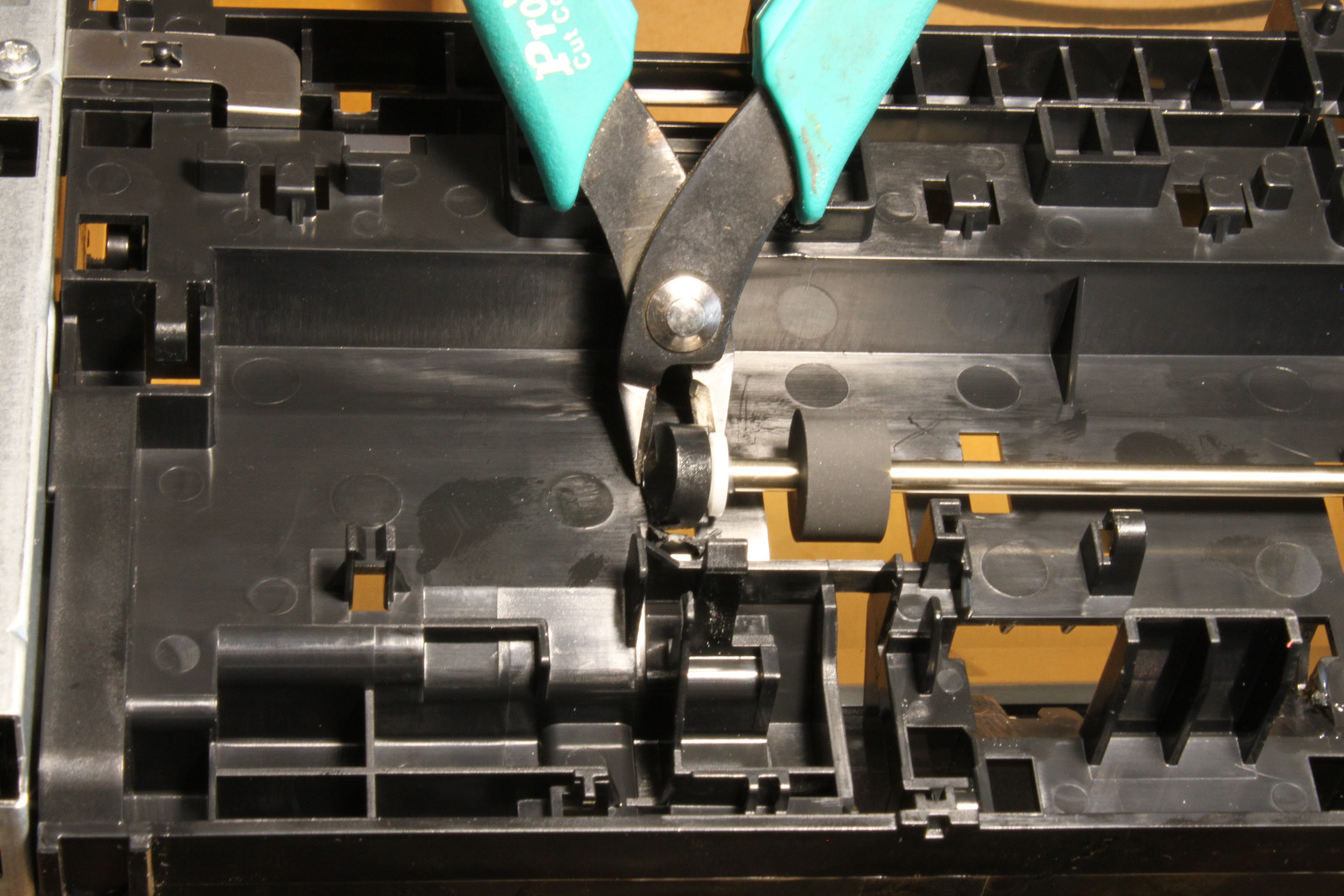
The last part to be removed is the shaft across the rear of the printer with its two rubber rollers. The easiest way to do that is first to remove the little plastic "flag" mechanism by just cutting or pulling it loose. Then cut the plastic end support completely off, freeing the end of the shaft. Pull the shaft loose while releasing the tab on the gear and it should slide right out.
Cutting the Paper Platform
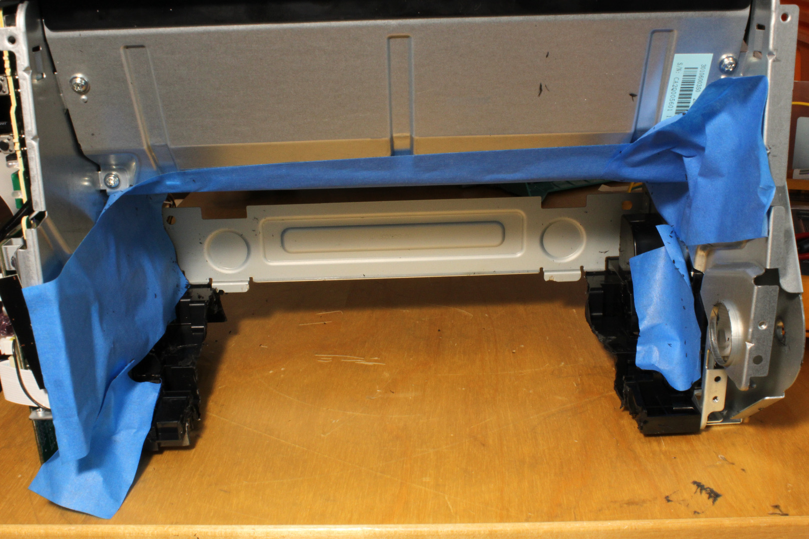
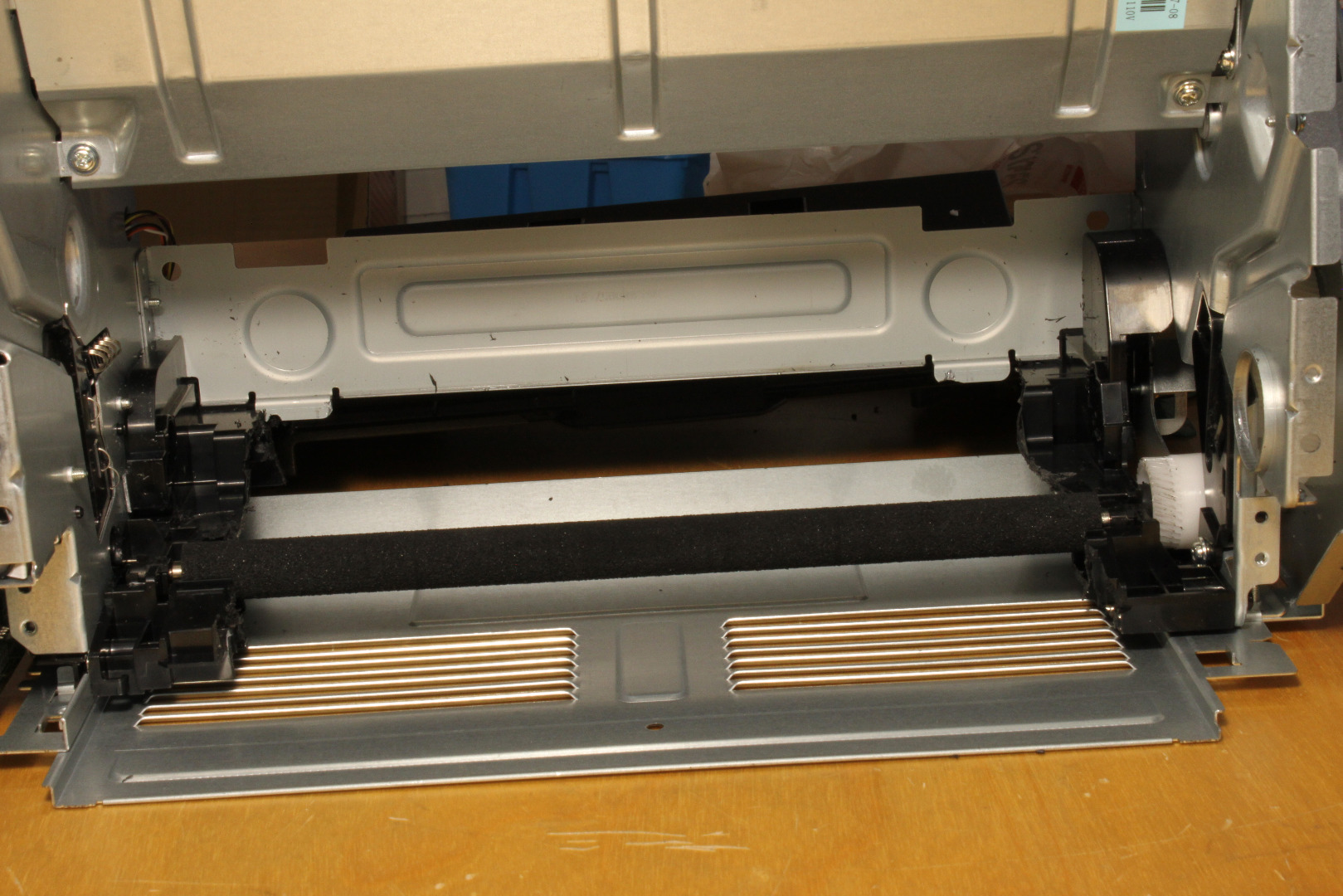
We are now going to remove a section of the plastic Paper Platform. This is necessary to create a flat
pathway through the printer to accommodate a six inch wide carrier with a mounted PCB.
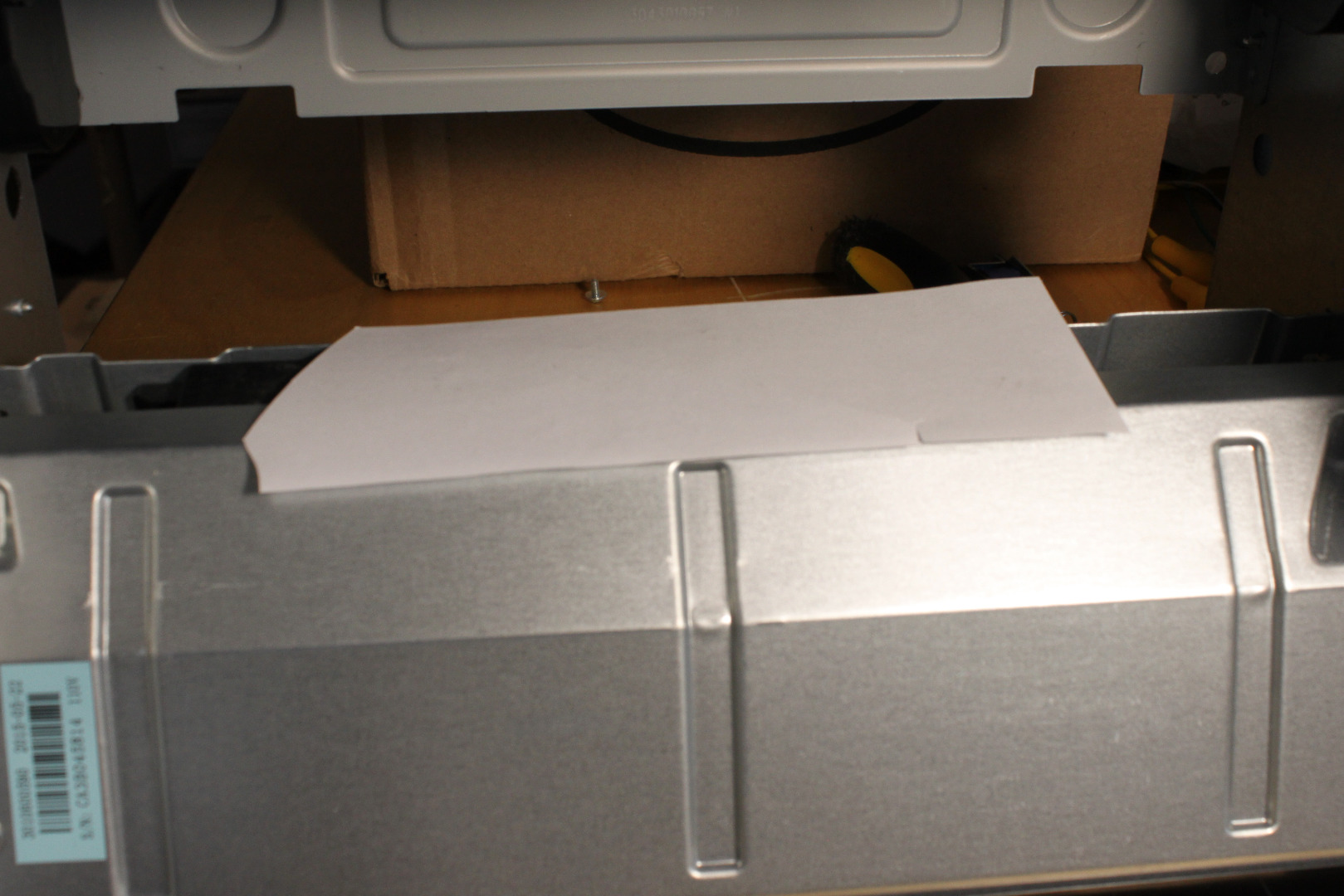
Use masking tape to cover and protect all exposed interior parts of the printer from chips. Use a
piece of paper over the laser window to keep adhesive on the masking tape from fogging the window.
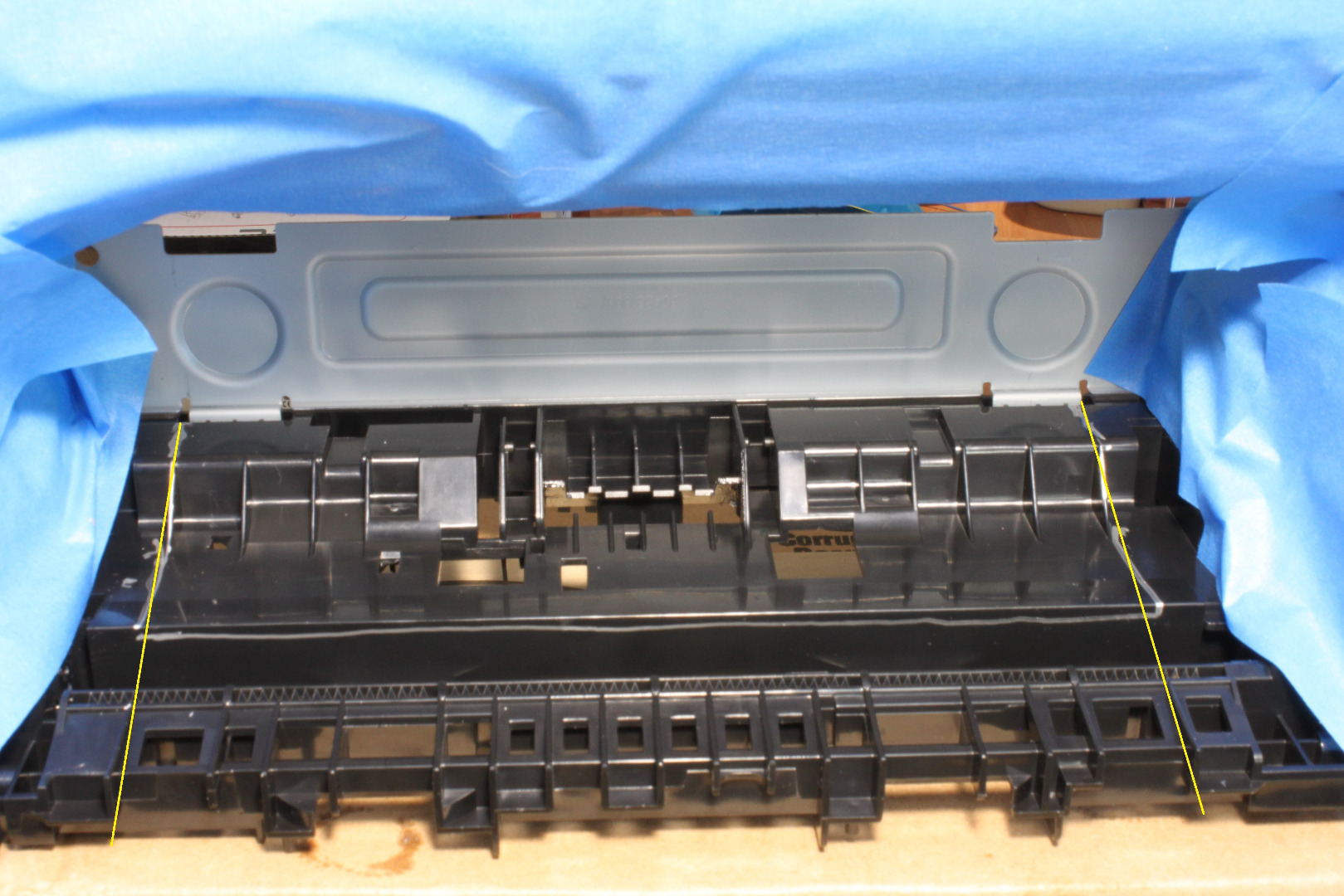
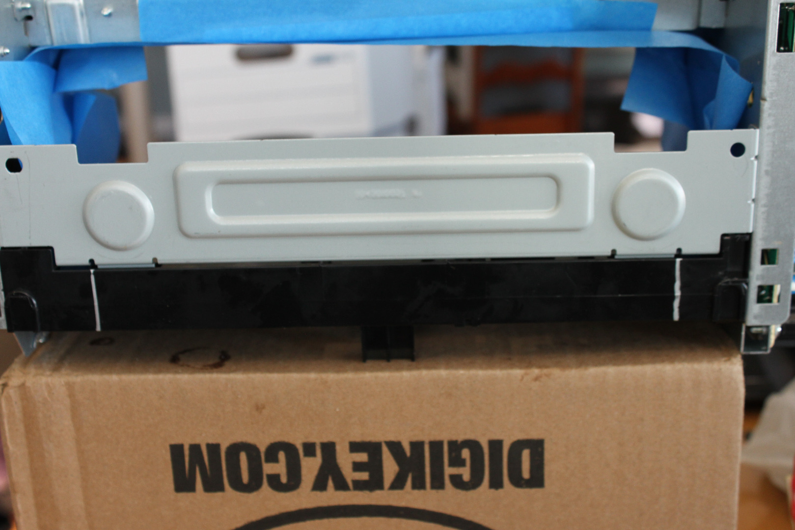
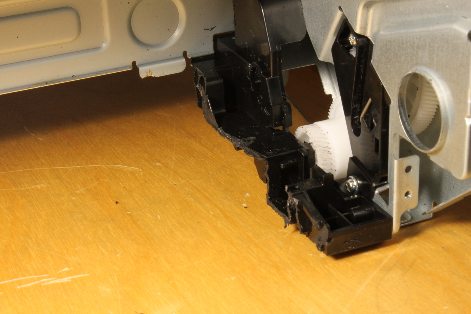
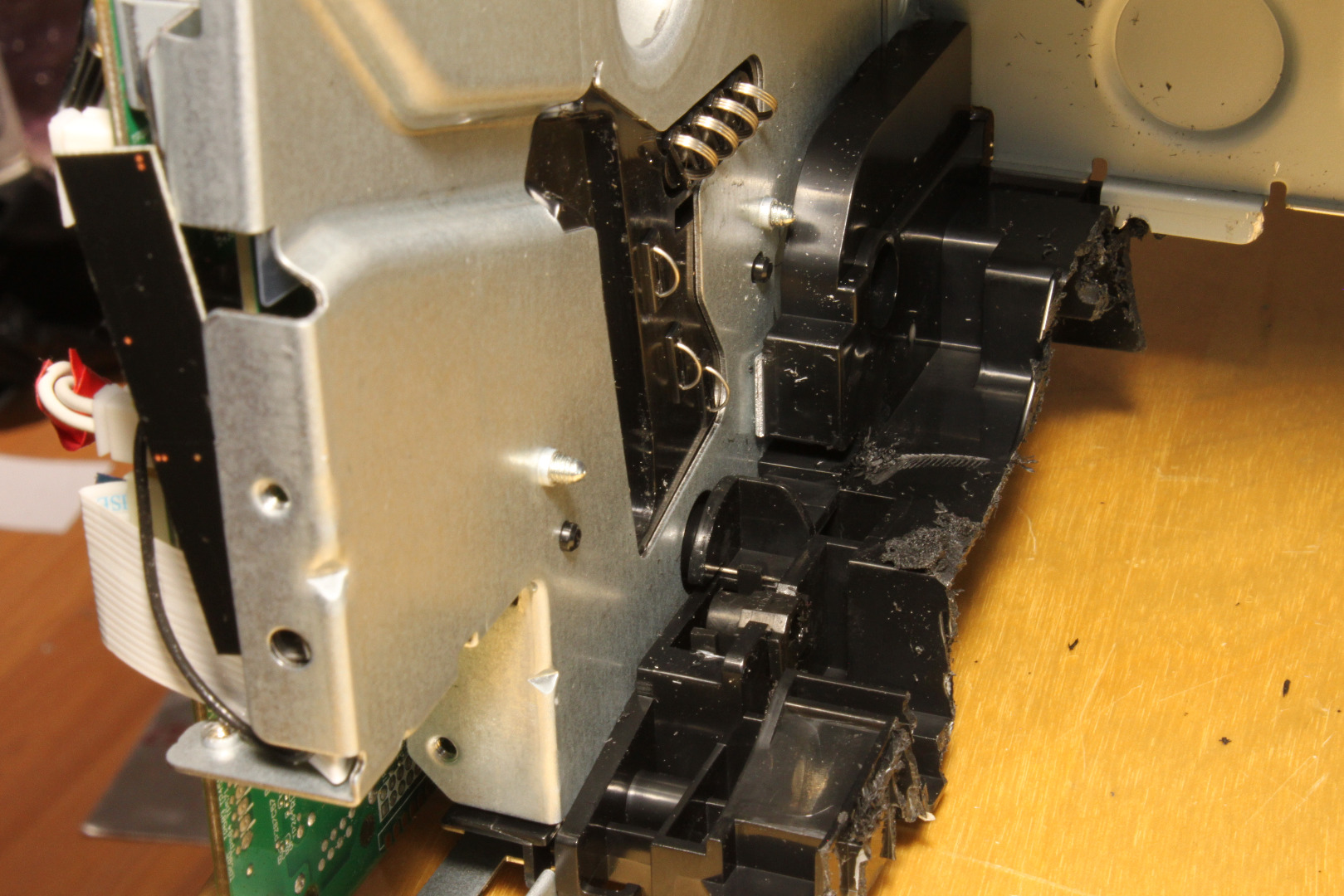
We will be cutting a piece about 8 inches wide going completely through the Paper Platform, leaving just a small piece on each side. In the photo you can see both thick silver lines and yellow, thinner lines. Follow the yellow lines, not the silver ones. Use the first "rib" on each side as a guide.
I used a Dremel with a router bit, but you can probably use a small saw instead. Make sure to extend the cut through the rear lip of the paper platform as well. See the photos.
Remove the cut piece then smooth out the cut edges with a file or sandpaper. If you use a Dremel there will be "crusts" of plastic that stick at the cut edges. These can easily be removed with your fingers.
Now vacuum up all the chips or use compressed air to completely clean up all the chips - you do not want chips to damage the drum while you are printing!
Remove the protective tape, check one more time for chips, then replace the Transfer Roller.
The MCU Board
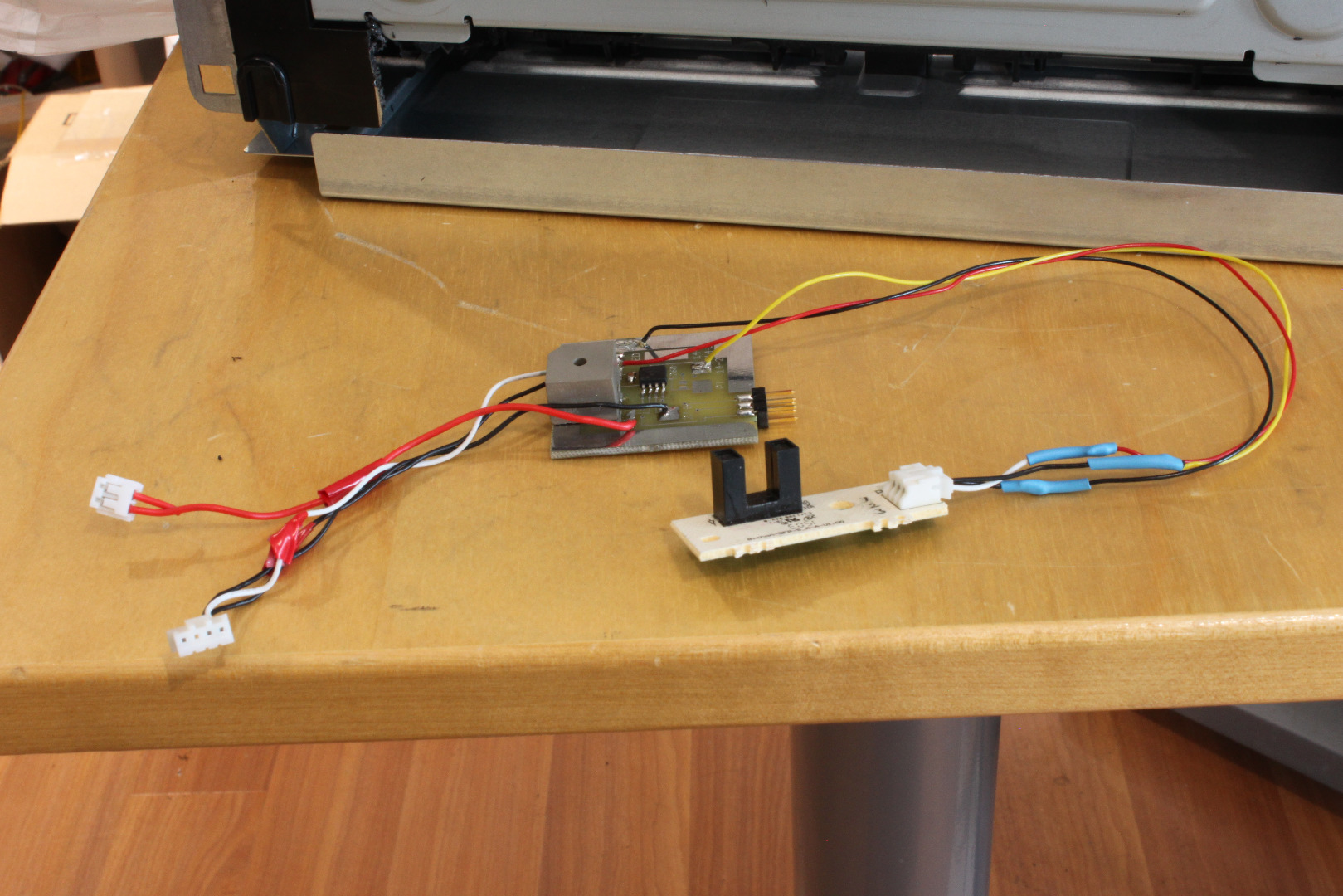
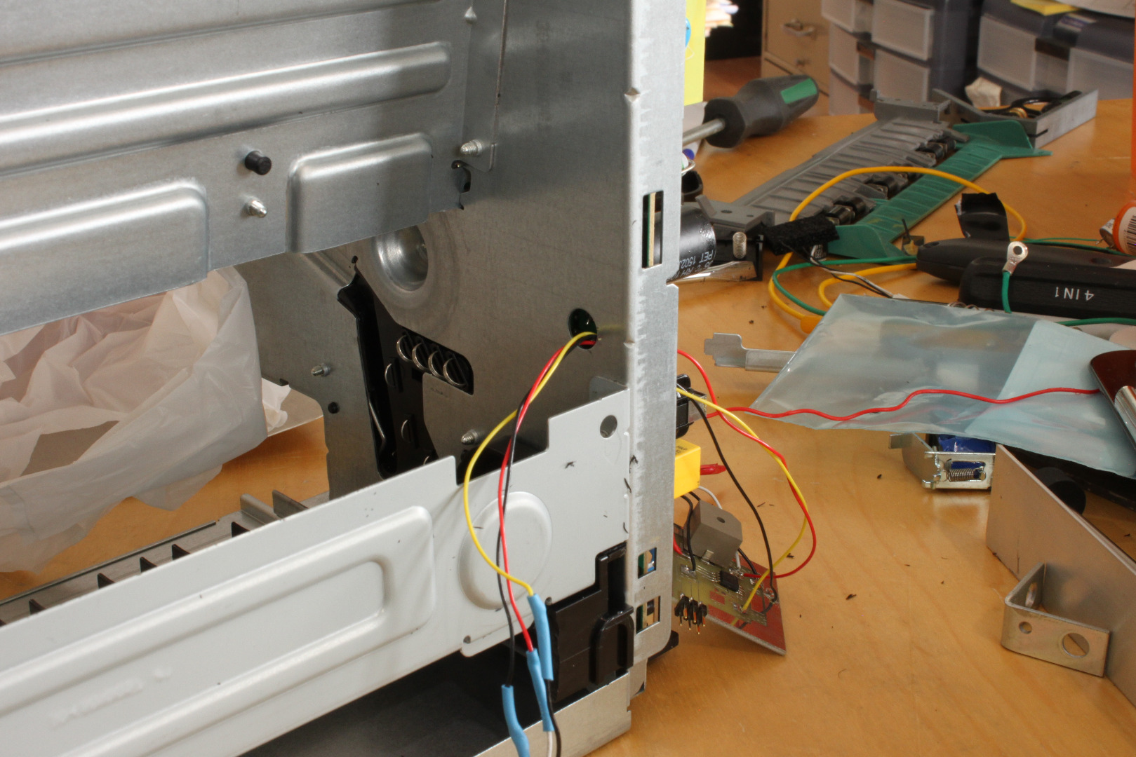
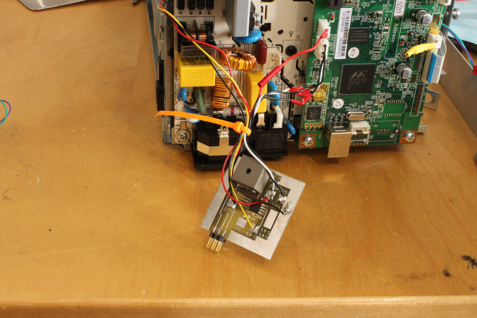
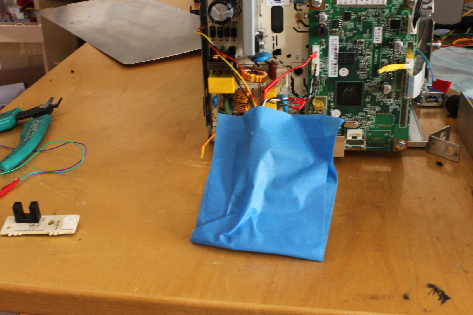
Note that the MCU Board has no voltage supply when the printer is in sleep mode. It is also off when there is no Toner Cartridge present. I therefore recommend that you program your MCU Board before connecting it to the printer.
Unlike the Lexmark E260 that has 2 clutches and 5 sensors, the Pantum 2502W only has 1 clutch and 1 sensor. The Paper Feed Clutch (PFC), pulls in when the printer is ready to print, allowing the gearing to pick up a piece of paper from the paper tray and feed it into the printer. As the paper moves along the bottom of the printer then up the back of the printer, the leading edge hits the Paper In Sensor (PIS), which, in this printer, has its own small circuit board. This drives the PIS high, starting the timing sequence for the printer.
While this process could probably be simulated with a timer chip (e.g., the 555), it is MUCH easier to do it with a microprocessor (mcu). As with the E260, I used an 8 pin Atmel ATtiny13 on a small circuit board. In fact, the MCU board you see pictured here is the same board I used in the E260, though the drawings included are for a new pcb.
To connect the MCU Board:
Remove the connector at J3 and J8. Cut the leads to about 4 inches from the connectors. Solder the leads
to the MCU board as shown in the schematic and drawings.
Add 8 inch extensions to the three wires going to the small sensor board, then solder the free ends to
the MCU board as shown on the schematic and photos.
Replace the connectors at J38 and J8. Pin 1 on J8 carries 24 volts and is not used, so cut it off near
the connector.
Remove the connector from P3 on the Sensor Board, then thread the sensor cable under the main pcb and out through the opening in the steel frame as shown in the photo. To do this you have to slide the connector under the pcb from the top and work it down to the opening. It's easier to do than describe.
Cover the MCU board with insulating tape and tuck it out of the way. Be sure not to cover the opening to the beeper because this will seriously attenuate the volume.
Firmware
The MCU's job is to detect when the printer is asked to print and then toggle the printer's one sensor at the appropriate time. The software necessary to do this is very simple.
;top
Delay 2 seconds.
Loop till a Carrier blocks the NPIS.
Loop till the Clutch Solenoid is activated (low).
Beep for 3.25 seconds, then stop.
;user pushes carrier in.
Loop til NPIS sees hole.
Drive PIS in printer high - printing timing starts
Delay about 3 seconds.
Drive PIS low
Go to top
The Firmware Assembly File and the Hex File are appended.
The Lateral Carrier Guides
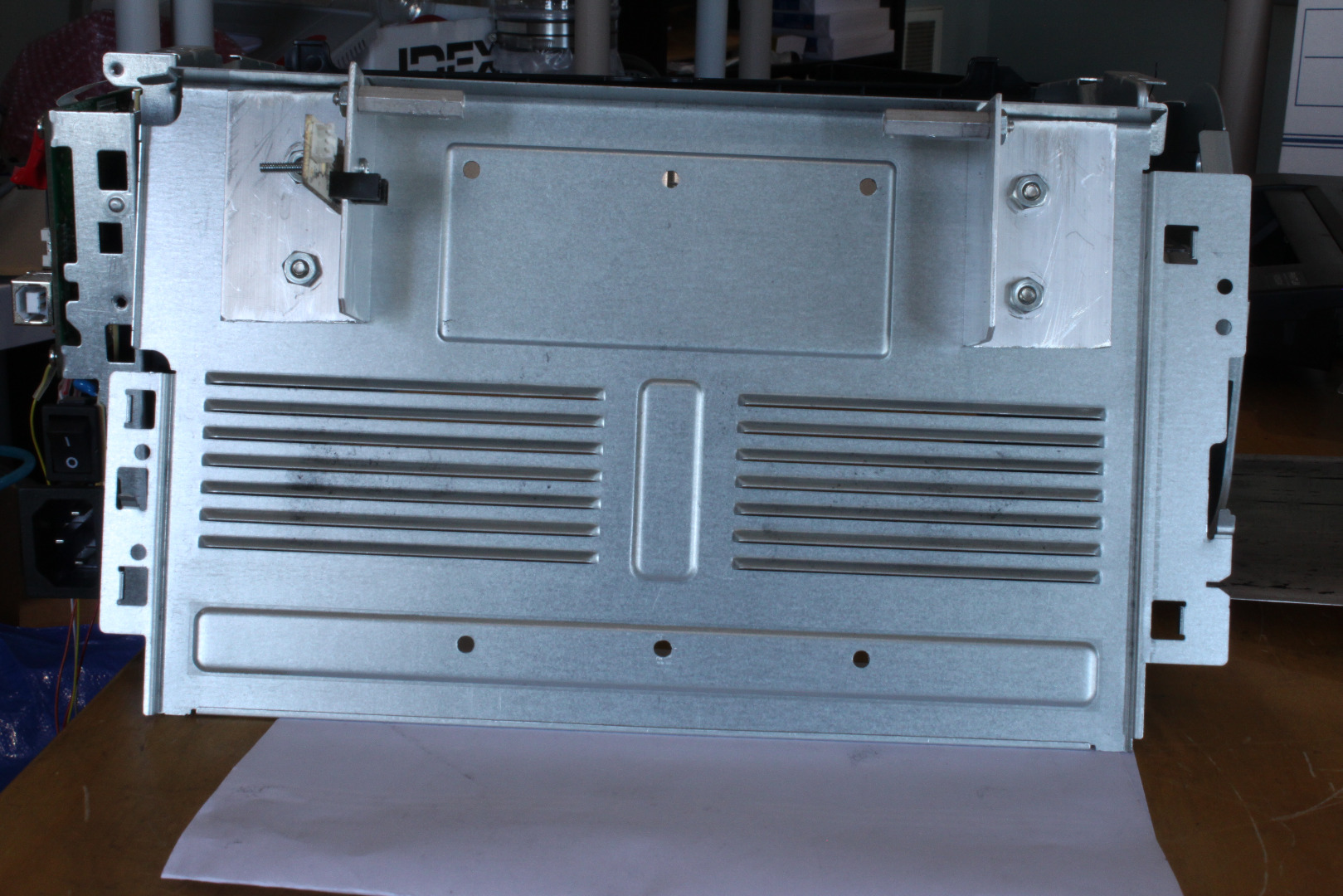
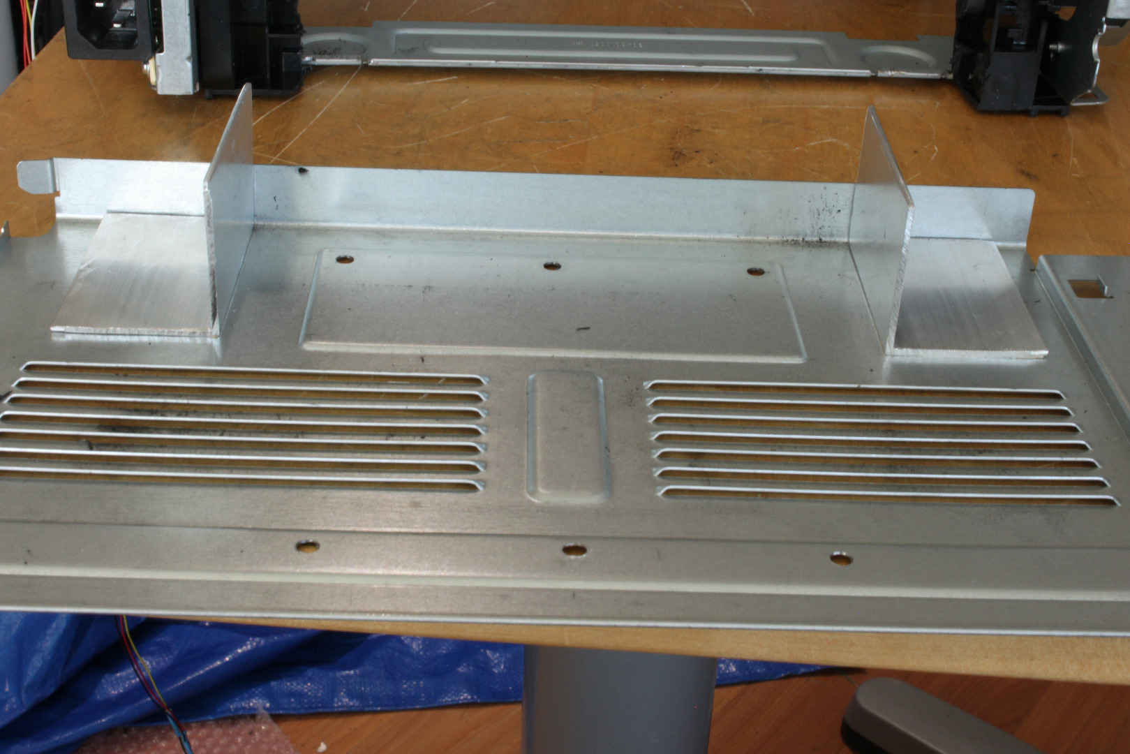
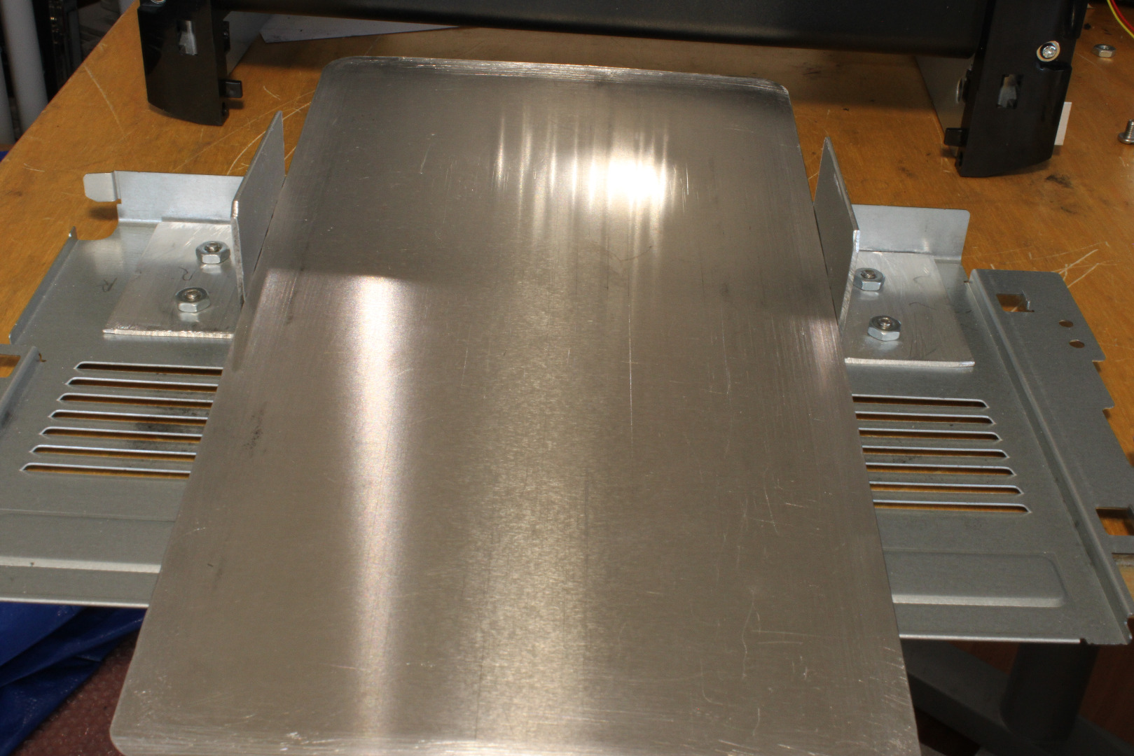
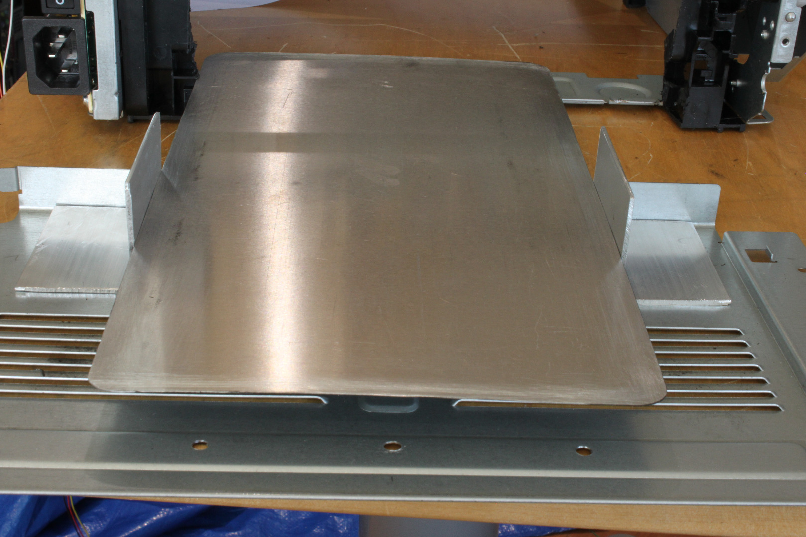
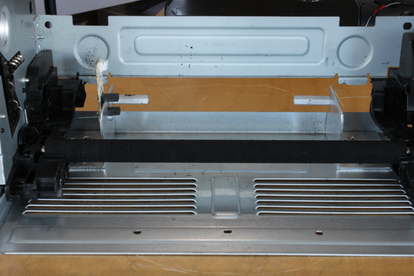
In this step we will be adding two pieces of aluminum angle that will guide the Carrier through the printer. As shown in the photos, the Lateral Carrier Guides (LCG) will be mounted on the Rear Plate (now the Bottom Plate) of the printer.
Cut two 2.25 inch long pieces of the 1.5 inch angle. Cover the outside of one leg of each of the angles with double sided masking tape. By using double sided tape you can firmly "stick" the angle in place on the Plate, making it easy to drill perfectly aligned mounting holes.
Stick them in place as shown, equidistant from the center, perpendicular to the flange, 6 inches apart, with the legs facing outward. The 6 inch wide Carrier should slide smoothly through the gap between the LCGs. Be sure that the LCGs are not longer than 2.25 inches because anything longer will hit the Cartridge when you insert it. Bevel the upper edges as shown to be sure the LCGs will clear the Cartridge.
Drill two .172 (11/64) inch holes through each LCGs and the Plate. Mark the right and left CGs, then unstick the LCGs and remove the masking tape,
The NPIS and Carrier Supports
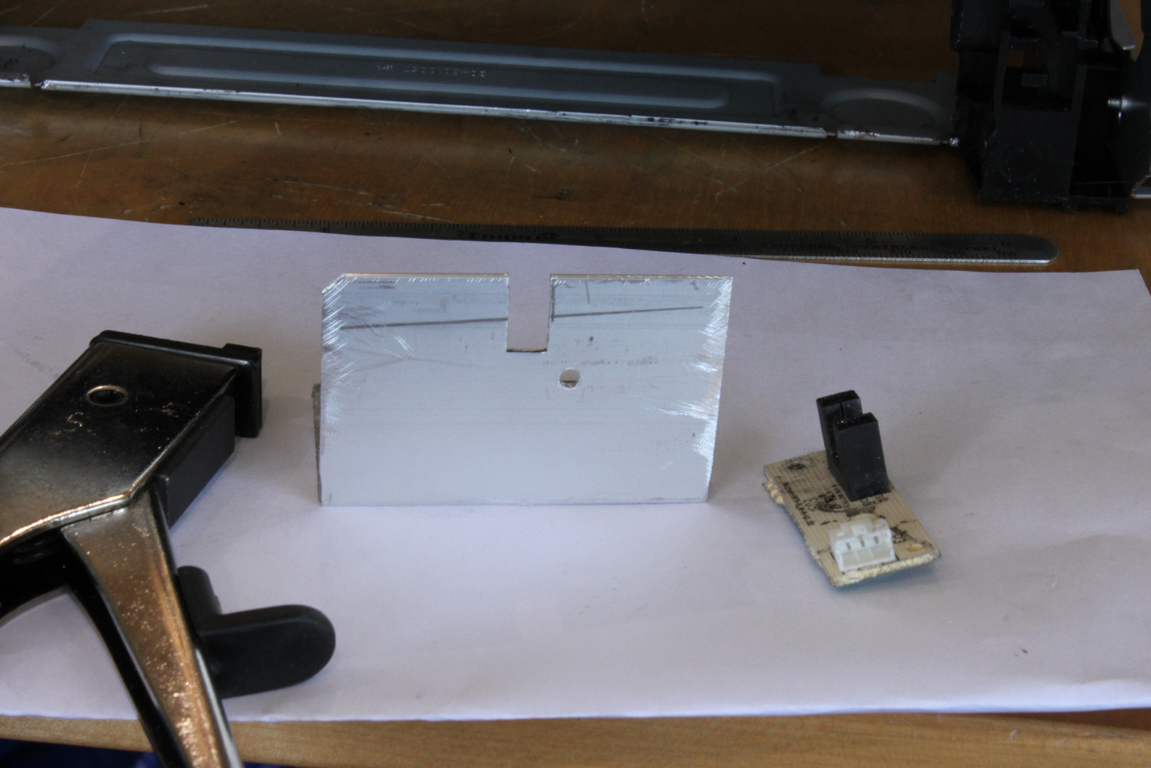
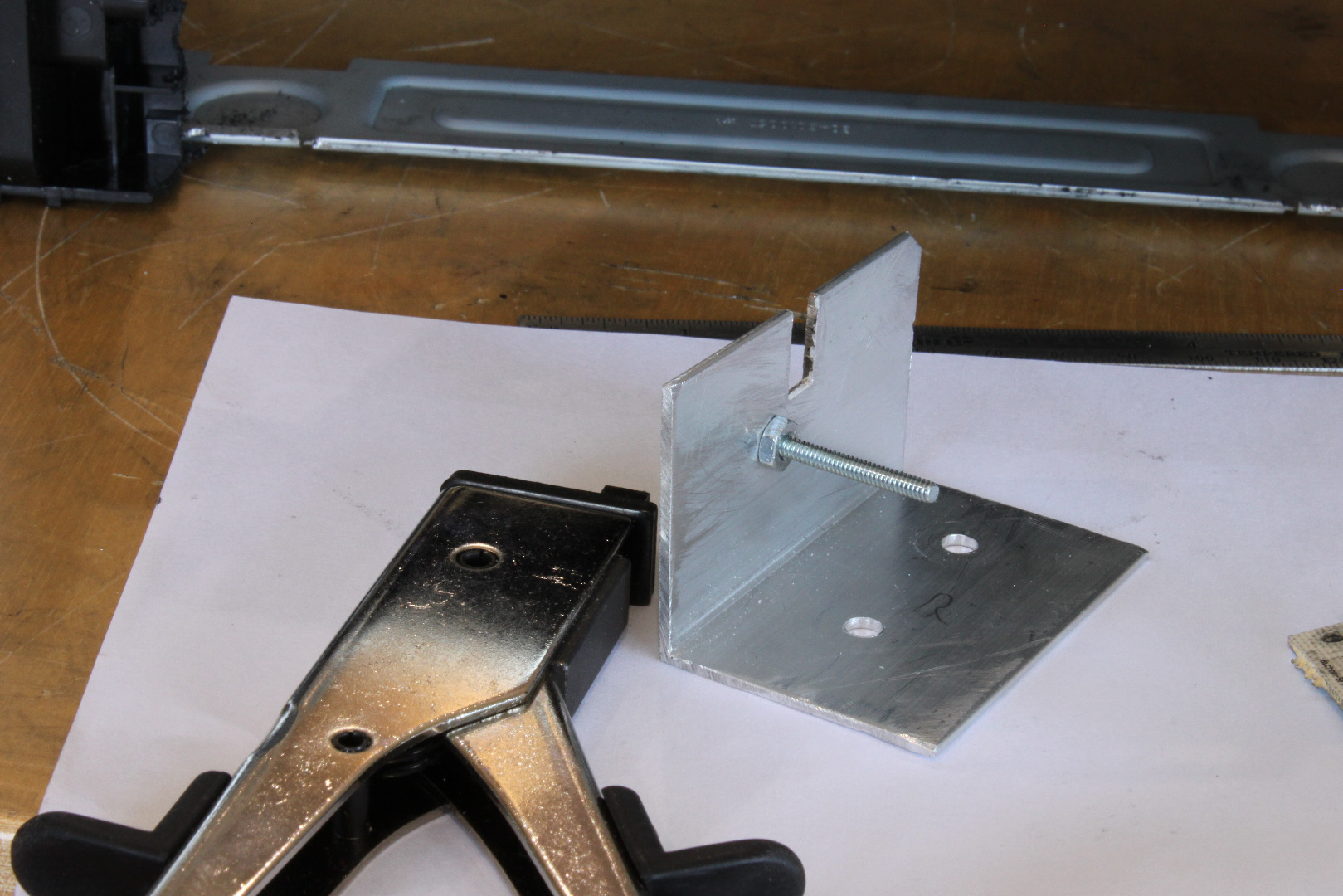
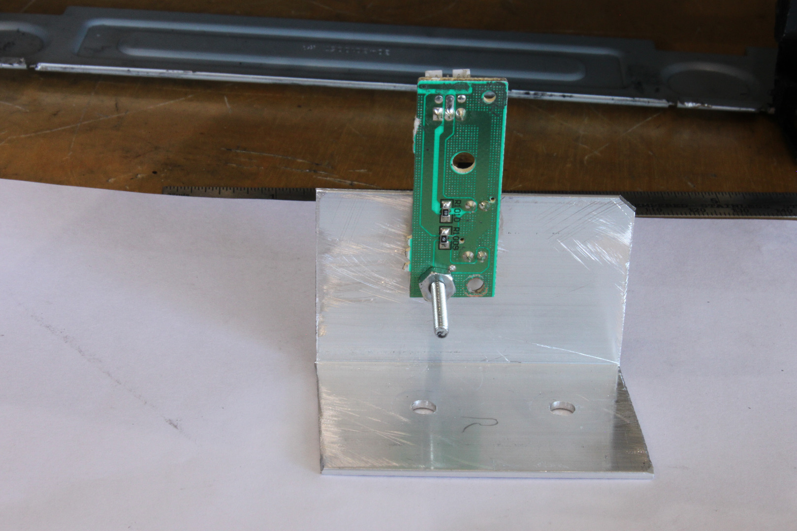
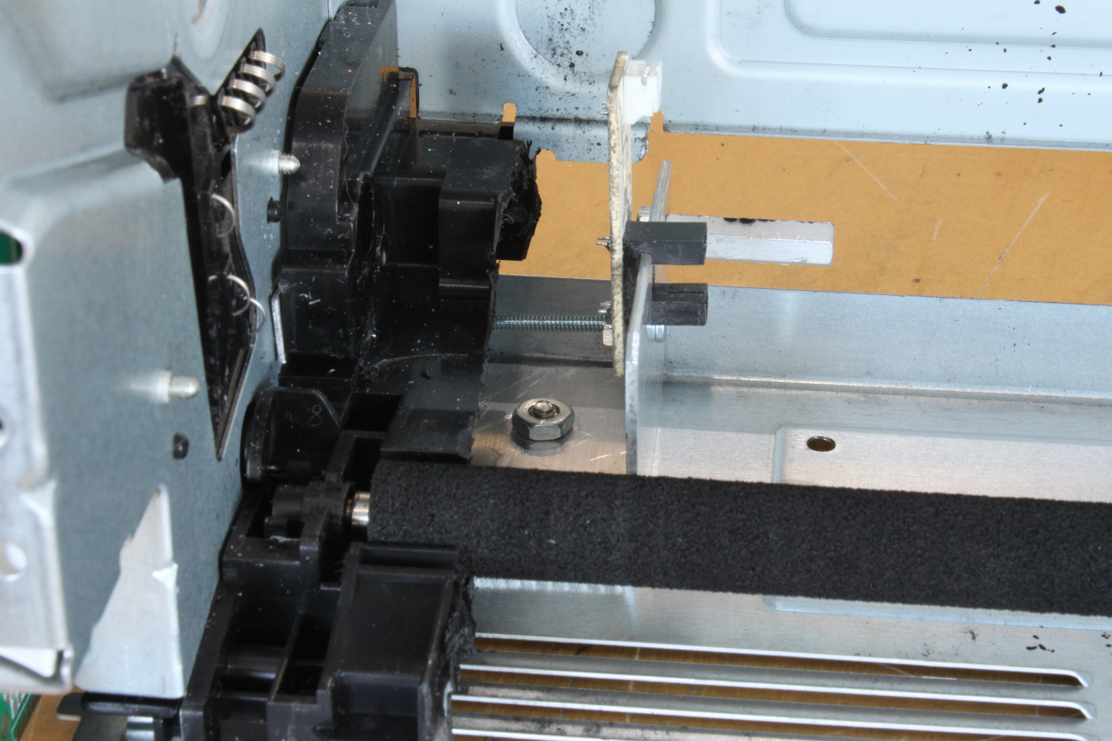
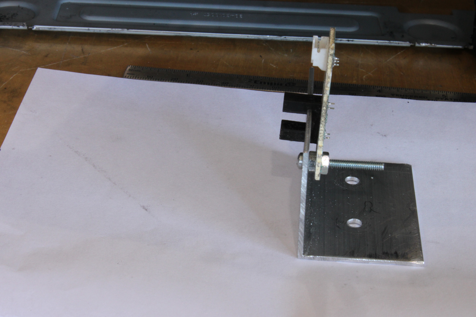
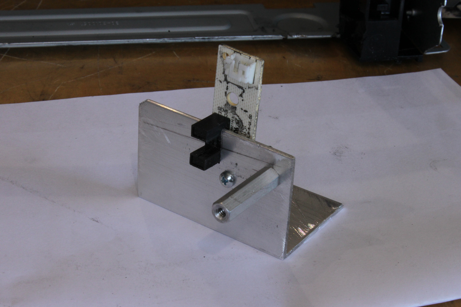
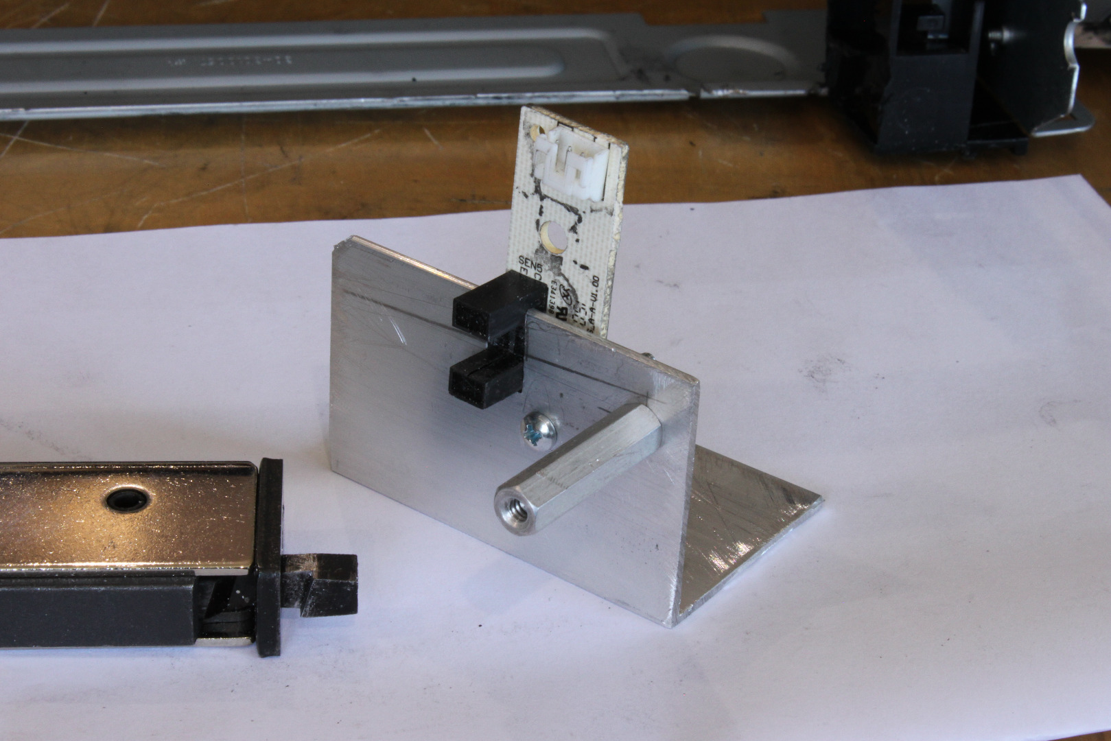
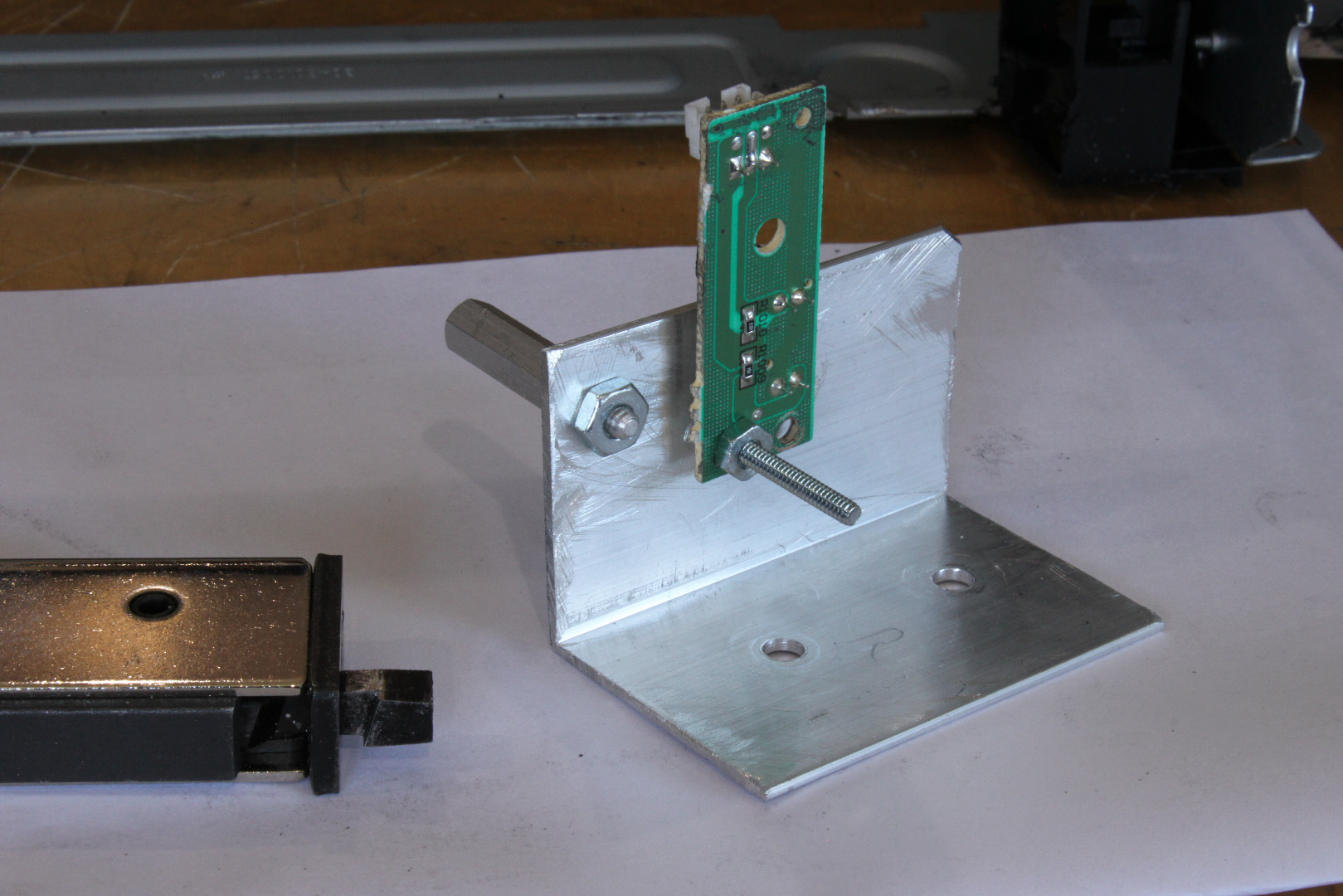
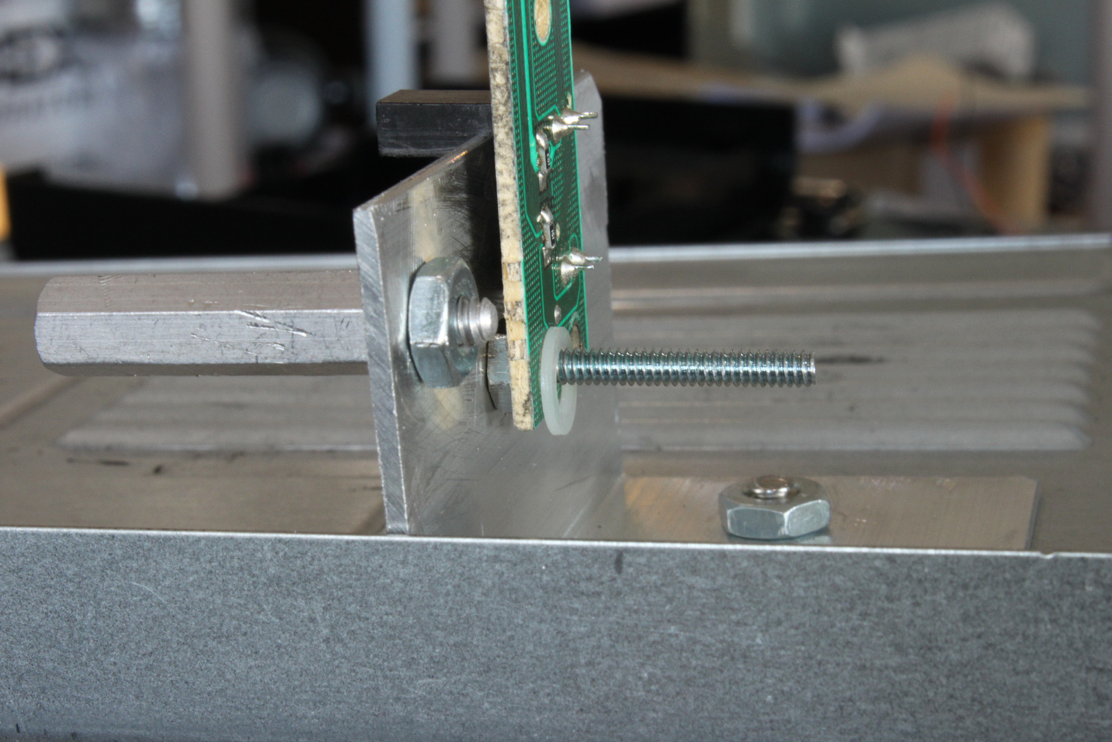
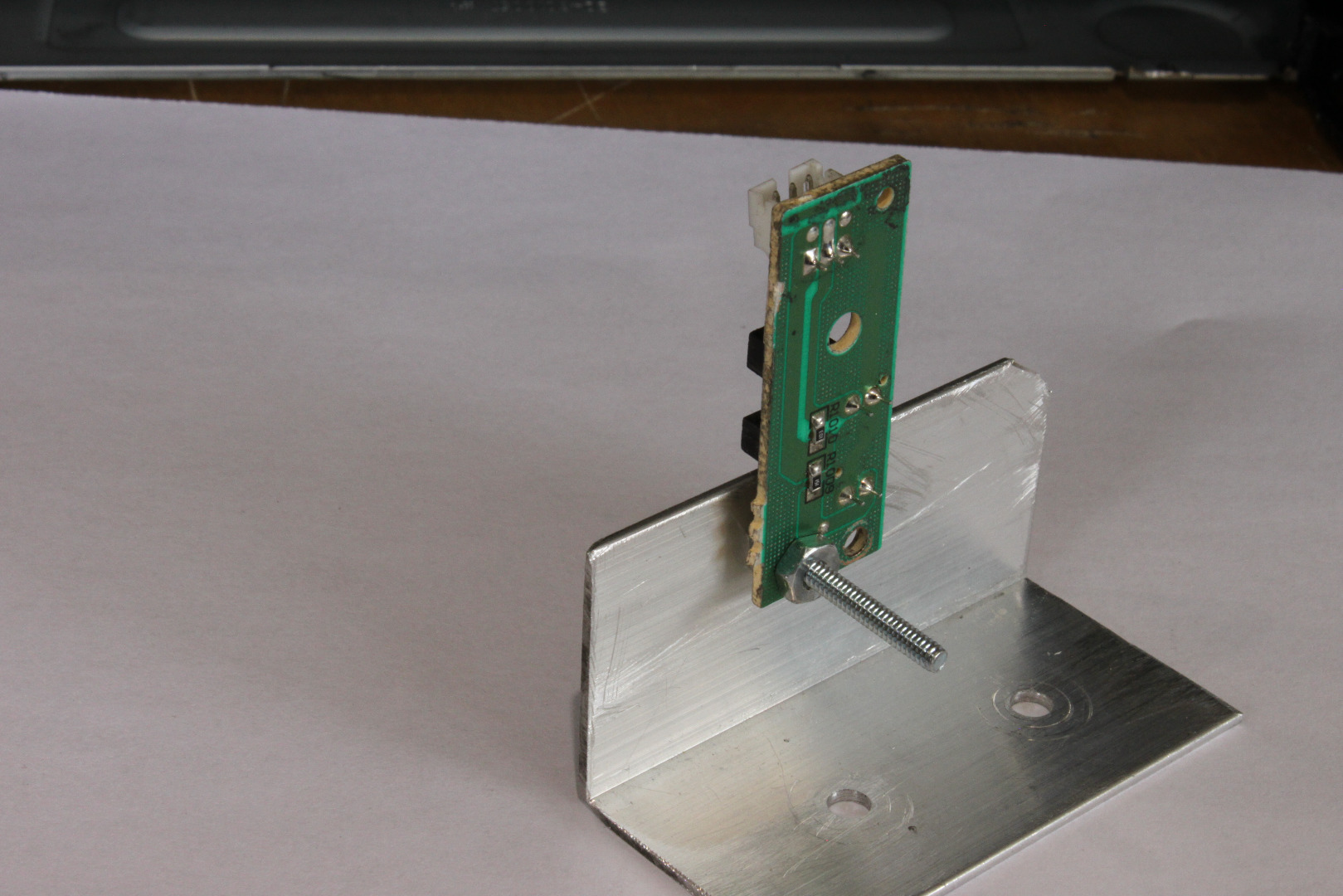
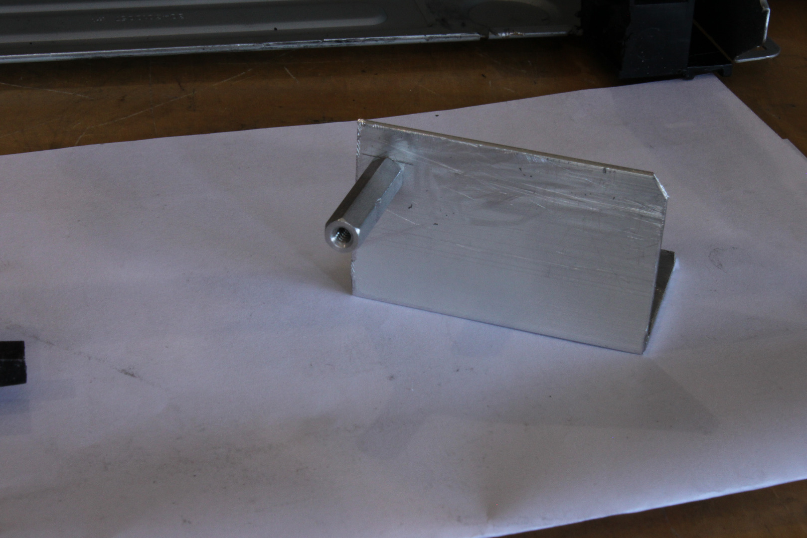
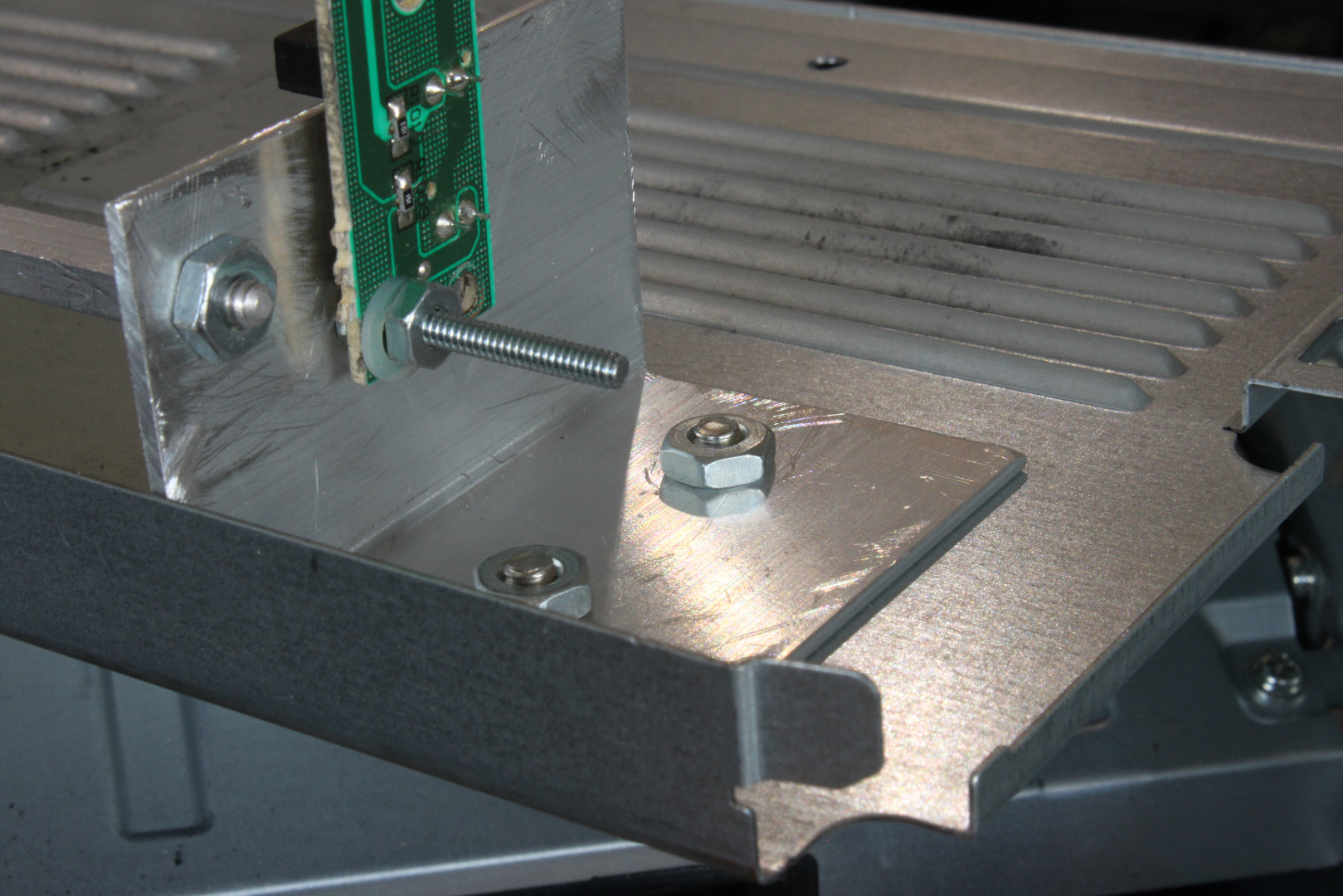
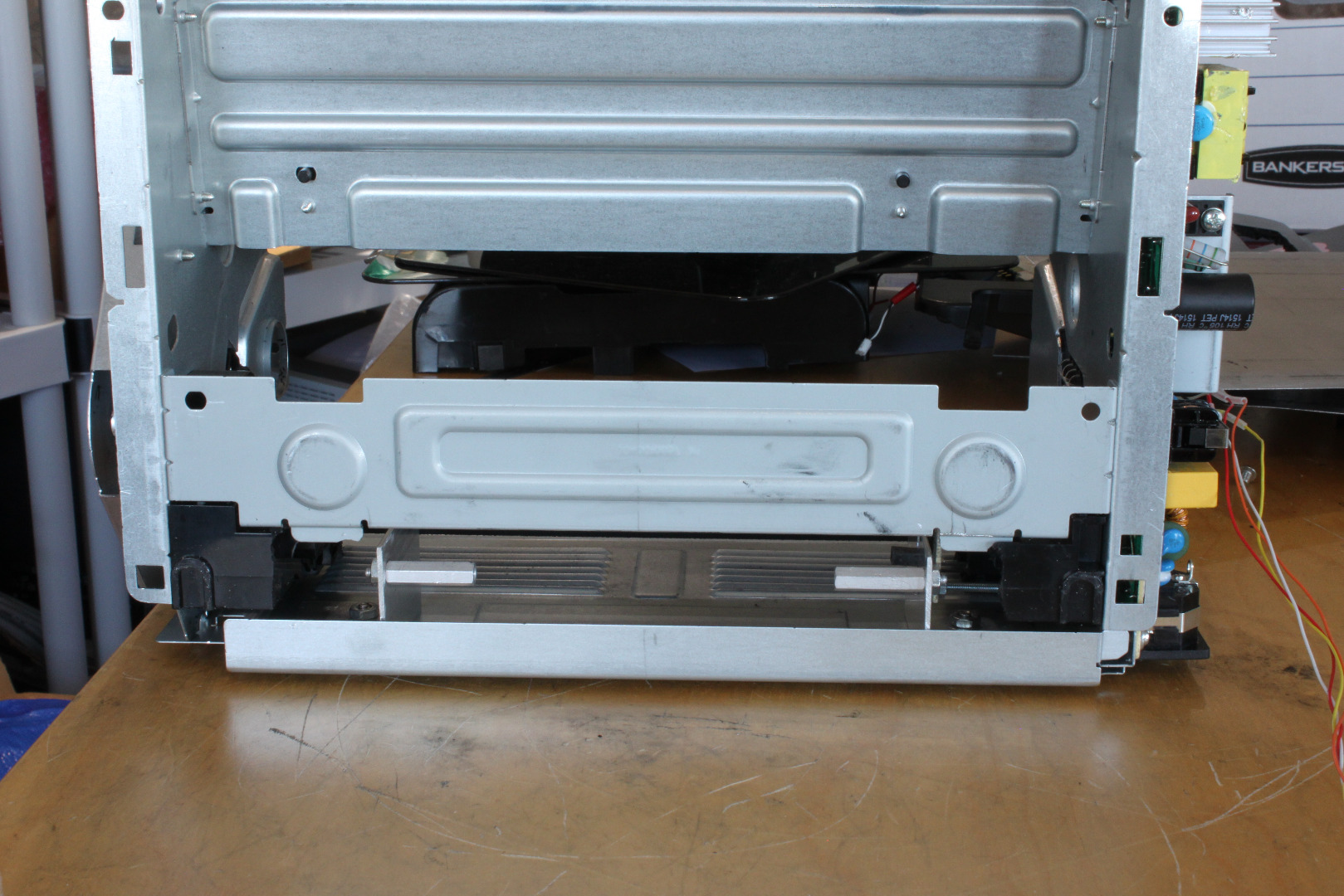
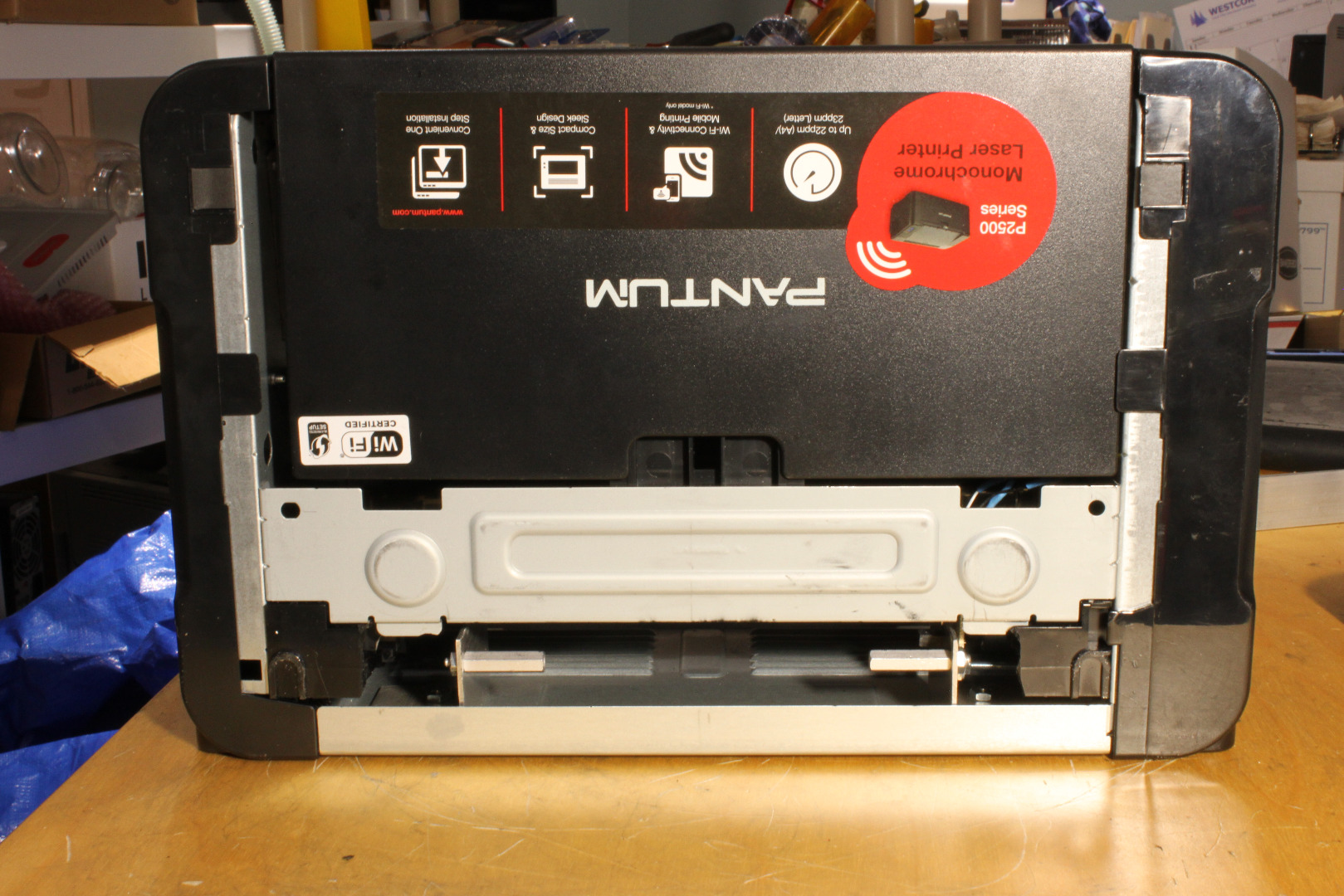
We are now going to mount the Sensor Board on the right LCG to use it as the New Paper In Sensor (NPIS) and add 2 supports for the Carrier.
Use a nibbling tool or saw to cut a .25 inch wide notch starting about 1 inch from the flange end of the right LCG. The notch should be about .5 inches deep. Slide the Sensor into the notch as shown, then mark the center of the small mounting hole on the back of the LCG. Drill a .125 inch hole in the LCG, enlarge the hole in the Sensor Board to .125 inches, then mount the Sensor Board as shown, using 4-40 hardware. Use a 4-40 nut as a spacer to keep the PCB slightly away from the LCG. This keeps the body of the sensor behind the plane of the LCG so the Carrier clears it. Use a plastic washer as shown to keep the nut from wearing through the green coating on the Sensor Board.
Drill a .141 (9/64) inch hole in each CG, .25 inches in from the rear edge and .375 (3/8) inch down from the top edge as shown. Mount a 6-32 spacer at each hole. I used 1 inch long threaded aluminum male-female hex spacers, but you can use whatever you have around. These spacers support the Carrier while you are waiting to print.
Mount the LCGs using 8-32 hardware, checking the photos to be sure everything is oriented properly. Adjust the space between the LCGs to allow your 6 inch wide carrier to slide easily between them.
Plug the connector from the MCU board into P3 on the Sensor Board.
The Rear Carrier Guide
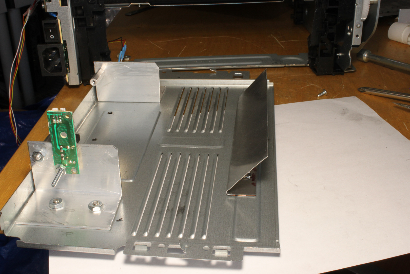
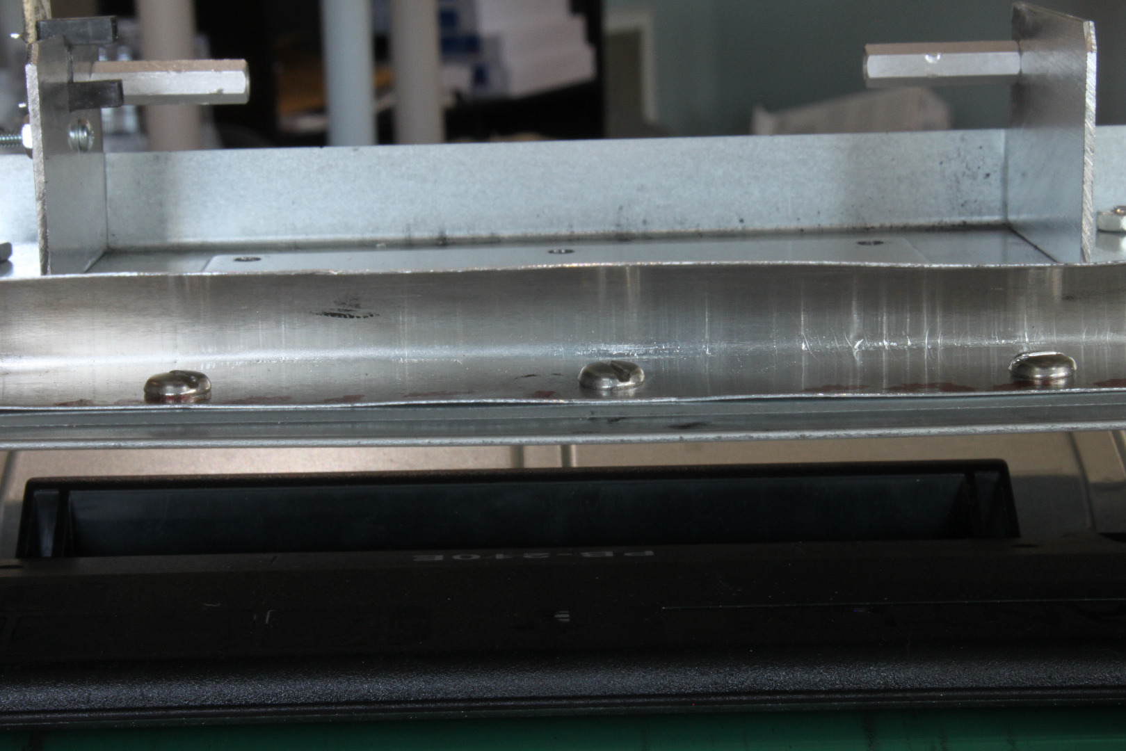
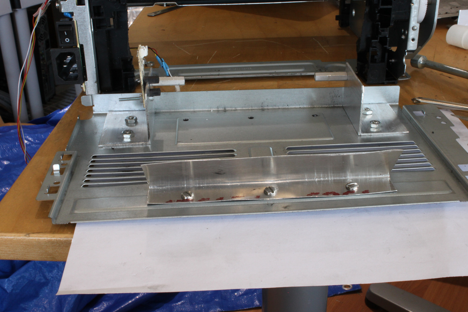
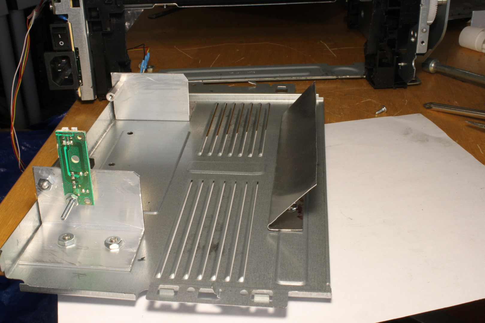
The Rear carrier Guide (RCG) redirects the Carrier as it passes through the printer and guides it out through an opening in what used to be the top of the printer. It is made from a 2.5 inch long piece of the 6 inch wide x .020 thick aluminum sheet that we used for the Carrier.
Cut and carefully deburr and smooth all the edges. Make a right angle bend about .75 inches from one end as shown. This can be easily done by bending the sheet over a straight edge. Then, using double sided masking tape, stick the RCG on the Plate, aligning the rear edge of the RCG on the rear edge of the last ridge of the Plate.
Then drill three .172 (11/64) inch holes through the RCG and Plate. Remove the masking tape and mount the RCG using 8-32 hardware.
Finally, bend the free edge of the RCG back over the mounting bolts as shown. Final adjustment can be made after the printer is reassembled.
Cutting the Top
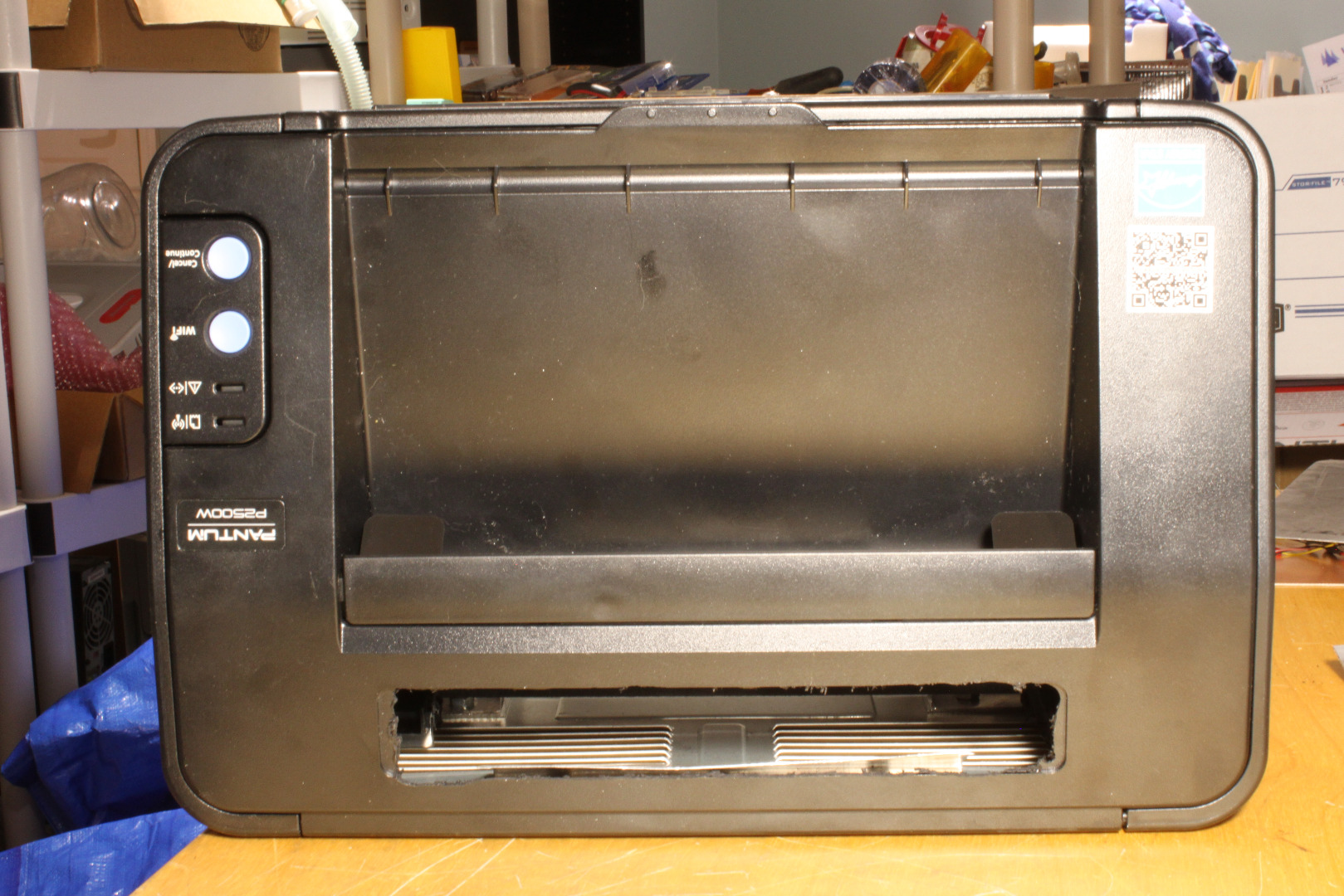
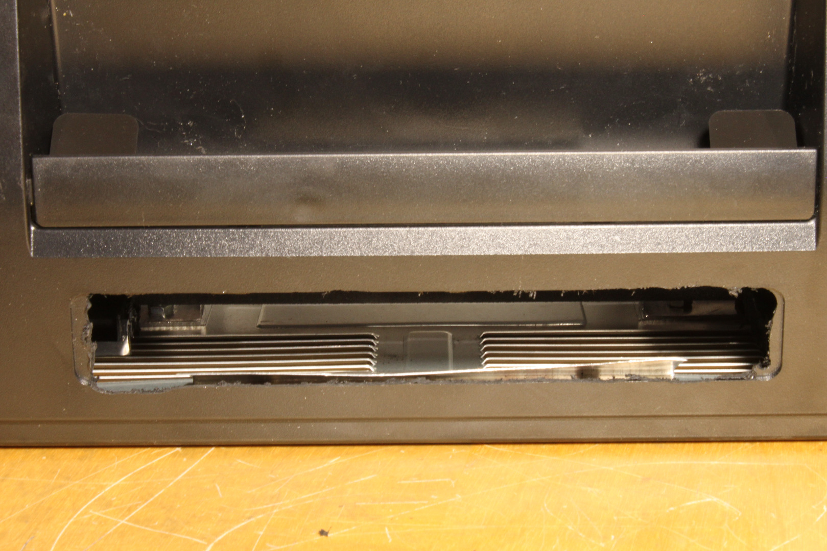
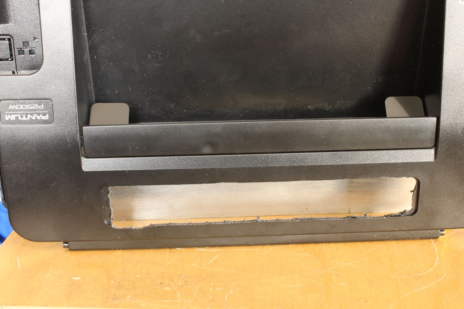
As noted earlier, the Pantum 2502W actually prints as the paper runs up the back of the printer. To print PCBs, we will place the printer rear down and feed the Carrier along the back, which now becomes the bottom of the printer. Since the Carrier is relatively inflexible, at least compared to paper, the Carrier will have to exit through what used to be the top of the printer.
Use a Dremel or saw and cut a slot in the plastic Top of the printer as shown in the photos. Smooth and deburr the cut edges.
Put the Printer Back Together
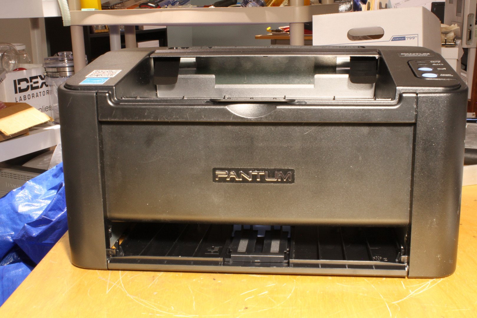
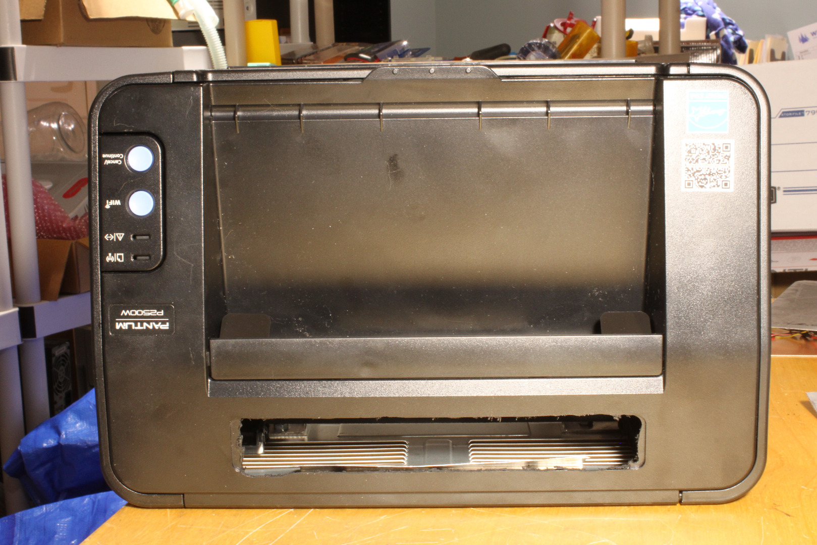
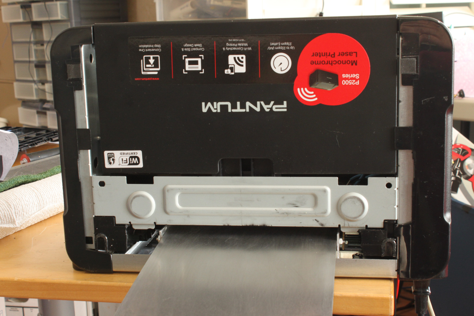
Cover the MCU Board with electrical tape, being sure not to cover the opening to the Beeper. Tuck it out of the way as you replace the Right Side Cover. Place the pivot pins of the plastic Top in the hole on the Right Side Cover and secure the other pivot as you replace the Left Side Cover. Replace the screw in the Left Side Cover and use the screw left over from the Fuser Rear Plate in the hole the Security Screw was removed from.
Close the Top and adjust the Rear Carrier Guide as shown in the photos. It should end just above the bottom lip of the slot in the Top.
Finally, take the Front Paper Guide and REVERSE it as shown. Then use a screwdriver blade to put the pivots in their holes. Instead of covering the front of the printer, it will now serve to cover the bottom of the printer.
The Carrier
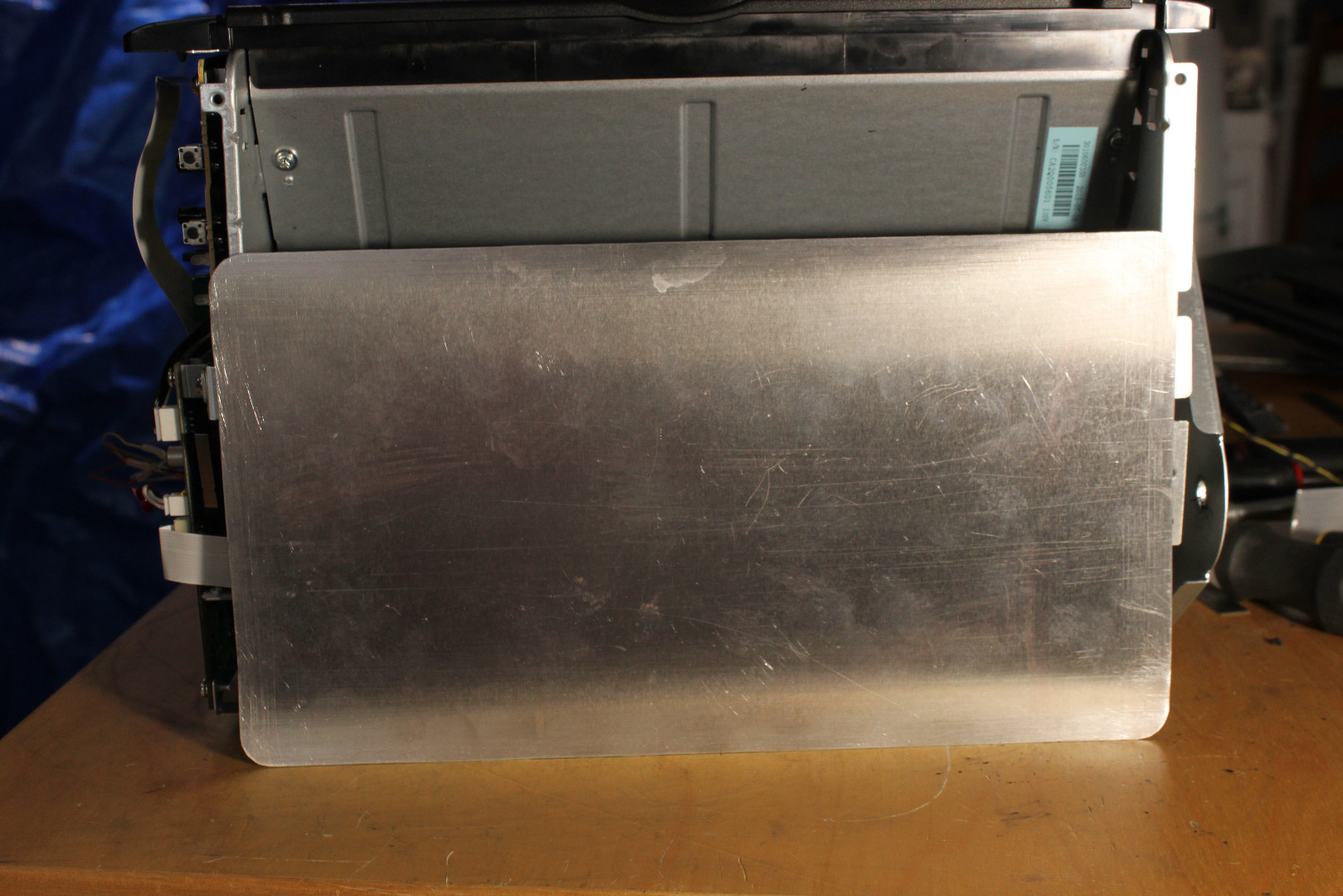
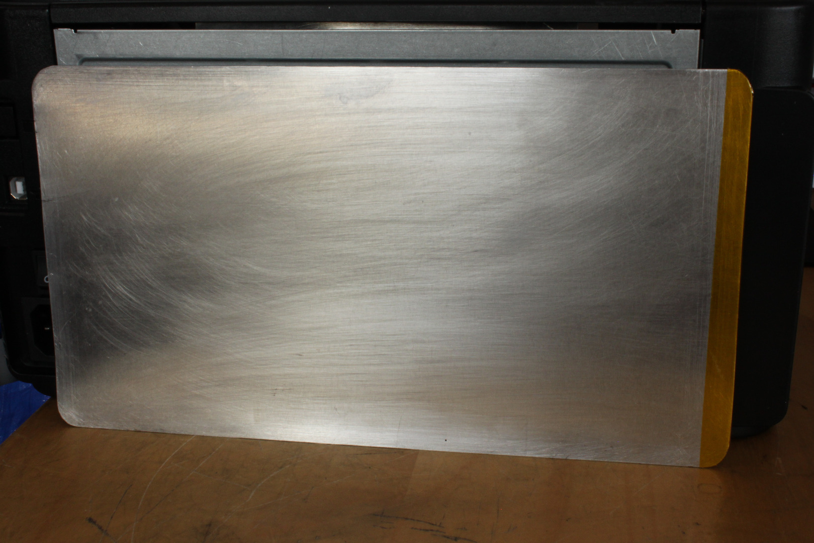
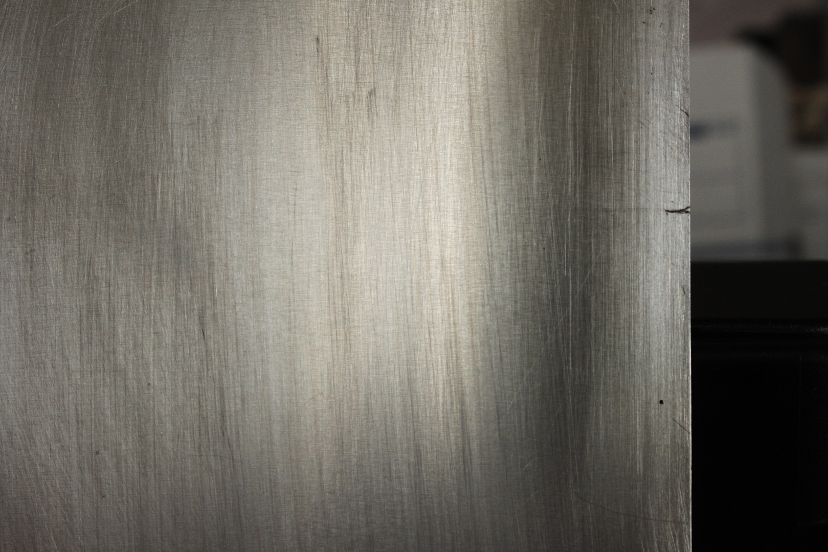
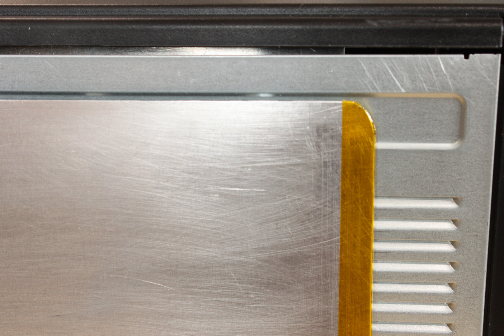
Make a 6x11 inch carrier by cutting an 11 inch long piece of the 6 inch wide x .016 thick aluminum sheet. Then round all 4 corners and sand all edges smooth. Be especially careful to sand down any "ridges" on the long sides of the Carrier as these can make permanent gouges in the Drum!
Place a piece of either vinyl electrical tape or Kapton tape over the leading edge of the carrier, folding it over the edge so that half is on each side of the carrier. Kapton tape is thinner than the vinyl, making insertion into the rollers a bit easier, but the vinyl works quite well. Cut the tape around the beveled corners. This protects the printer drum from getting gouged as the carrier enters. If there is lettering printed on your carrier you can remove it with acetone on a paper towel. Using a 6" carrier the maximum PCB width is 6 inches, but I usually use 4 inch wide PCBs.
Temporarily reinstall the toner/drum cartridge. Slide the Carrier through the slot of the NPIS, and slide it gently forward till it just touches the cartridge. Mark the spot on the carrier at the rear edge of the NPIS, then back the Carrier away from the cartridge.
Remove the carrier. Now drill a small hole in the carrier, located about 1.5 inches behind from that mark and about 5mm from the edge of the carrier. I used a .026 inch drill.
This hole is the "trigger" for the NPIS. As the carrier moves into the printer, the NPIS is blocked by the opaque metal carrier. However when the hole arrives in the center of the NPIS, the IR from the led hits the phototransistor and the output of the sensor goes from high to low for a very short time (5.5 msec for a .026 inch hole). The MCU recognizes this transition and starts the timing for the print.
Using the Printer
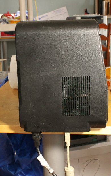
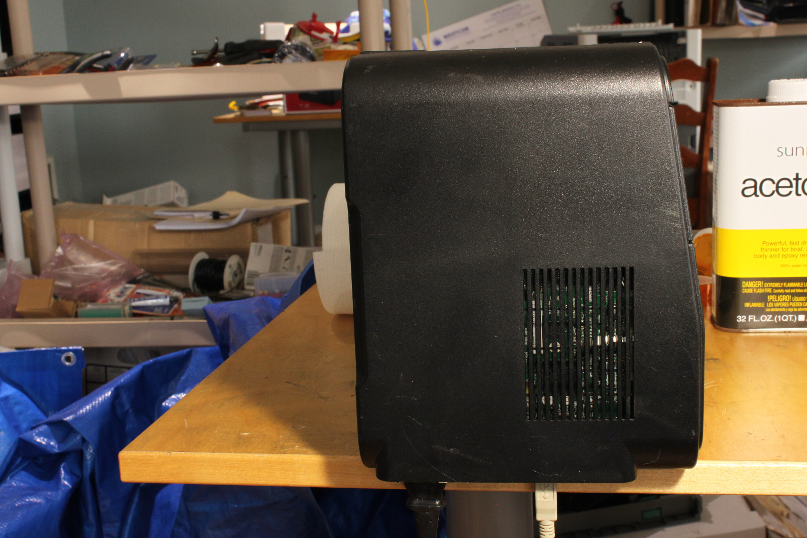
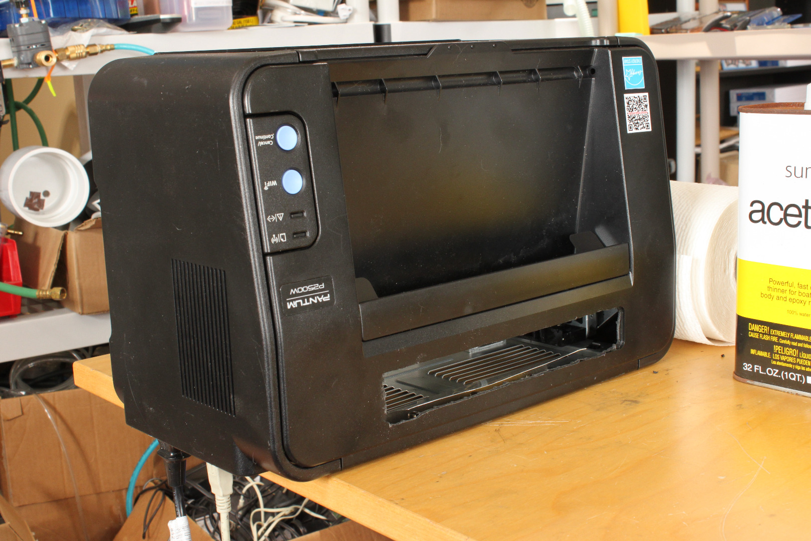
Since the printer now prints as the Carrier moves up the back of the printer, the printer now has to be positioned with its back down and front up to print properly. This creates a problem because the USB and Power cords are located on the rear of the printer.
I experimented with several ways of "raising" the printer off the surface of the desk by adding extensions to the side covers, but finally decided that "simplest is best", and the easiest way is to position the printer at the edge of your desk or table and just let the USB and Power cords hang over the edge. Just be careful not to push your printer off the desk!
Printing a Centerline on the Carrier
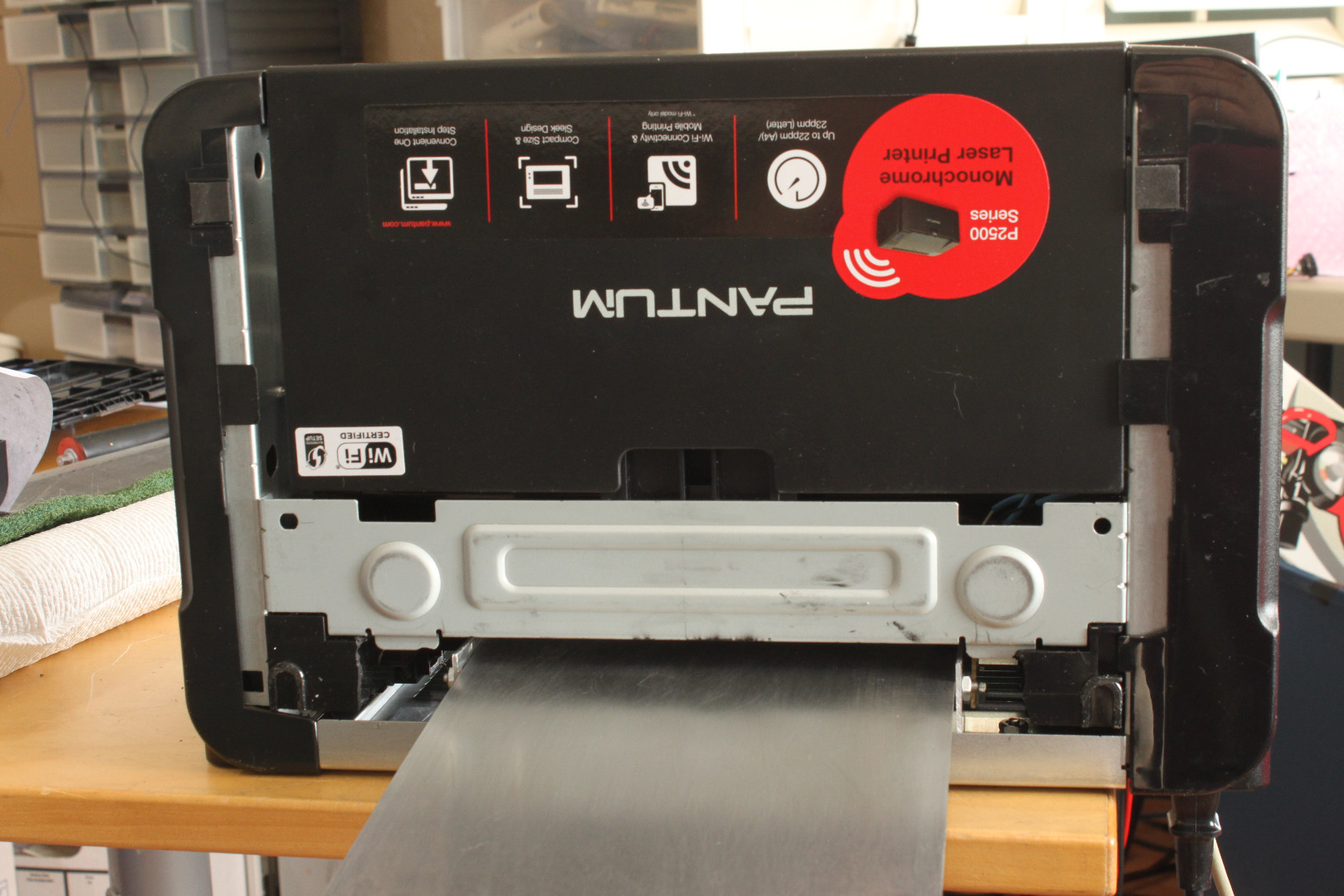
You can design your PCBs on any software that produces a printable image. However, at the very least it should have a way to place the print where you want it on the PCB. Additionally, if you are going to make double sided boards you should be able to print a mirror image of the design. I use the free version of Eagle. The learning curve is a bit annoying, but it does get the job done and is very flexible.
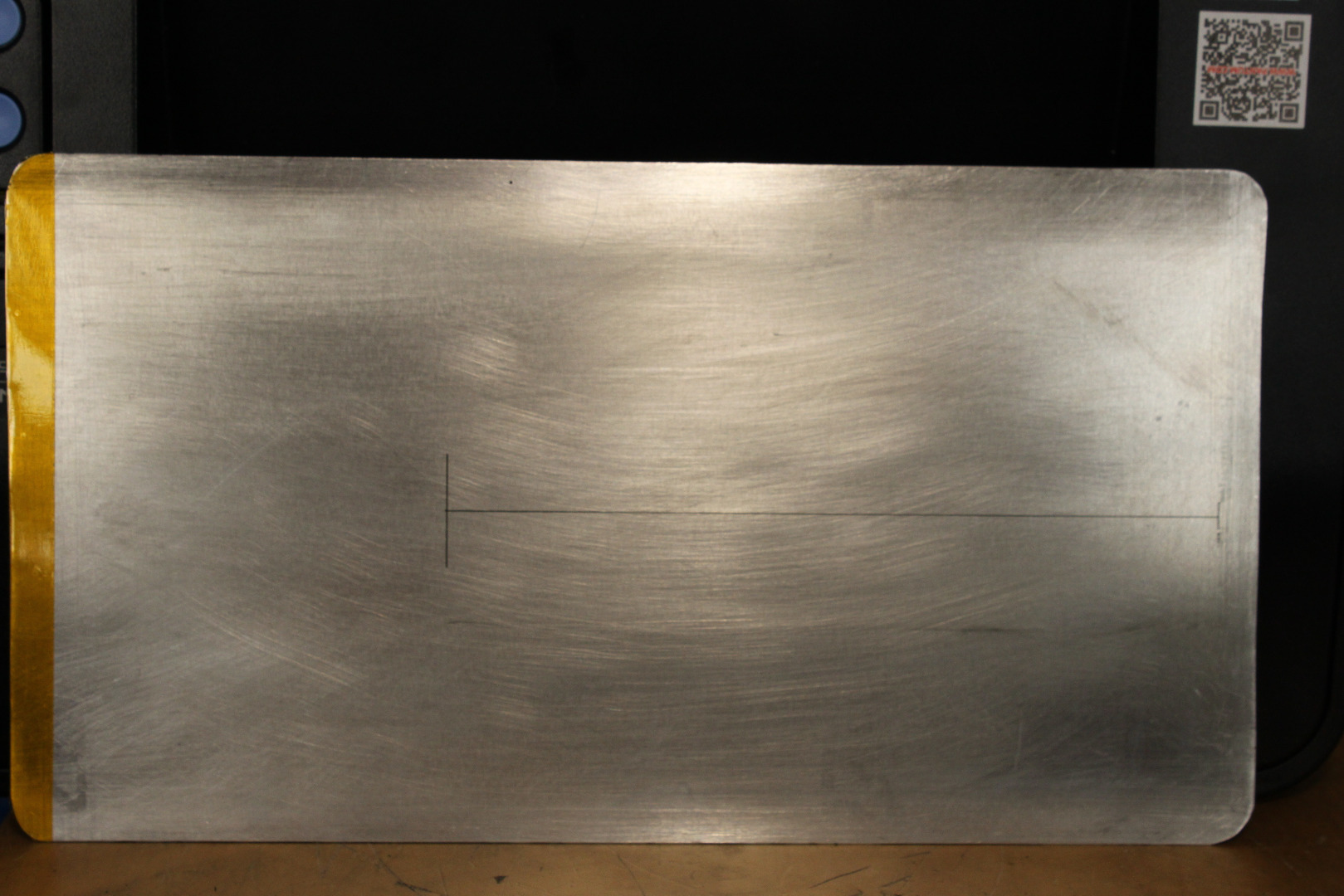
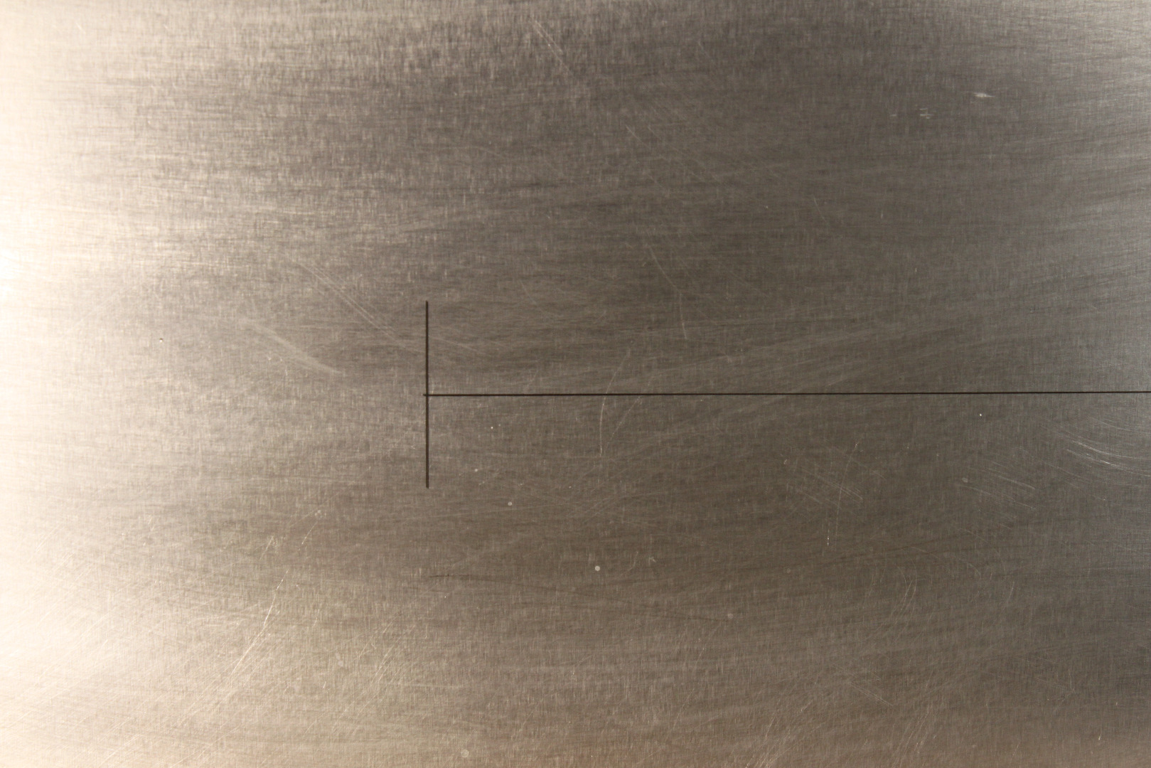
The printer creates double sided PCBs by printing each side of the board on a separate pass. To do this successfully we need to know the centerline of the printer's X axis, and also have a reference point on the Y axis. To do that we are going to print a cross on the midline of the Carrier.
Use your software to make a line about 7 inches long on the centerline. The line should be relatively thin - .005 inches works well. Draw a cross piece about .25 inches from the top and about 1 inch long. Set your software to print the line at the top center of the print with all 4 margins as small as possible. In Eagle I used .2 mm for the margins.
Sand the Carrier with a Scotch Brite green scrubby to smooth it and remove any oxide. Then clean the Carrier with acetone on a paper towel till the towel comes off the Carrier clean. Let it dry. The carrier will be cold from the evaporation of the acetone, so let it come back up to room temperature before printing.
Put in your best Toner Cartridge. Connect the USB and power cables and turn the printer on. Wait for it to finish booting. You are now ready to print.
Place the carrier in the NPIS slot and through the Lateral Carrier Guides (LCGs). Advance it till the front of the carrier gently touches the drum, then pull it back about .25 inches. Press "Print" on your computer to print the cross. You will hear a beep when the Clutch signals it is ready to print. When the beep stops it is time to slide the Carrier gently forward into the printer. You will have about 2 seconds to do this.
If your timing is off and the printer "errors out", remove the Carrier from the printer and wipe it down with acetone to remove any toner. Then turn the printer off and reboot it to try again.
Print the cross. Then reinsert the Carrier and print it again, exactly in the same position. Print it a third time, selecting "Mirror Image" this time. All prints should be superimposed, both in the X and Y axis. If they are not, wipe off the toner with a paper towel and clean the Carrier with a light acetone wipe. Repeat the print, being sure the Carrier is between the LCGs. You may need to reposition the LCGs to get it exactly square, but you can run it through as many times as you want till you are sure the alignment is perfect. Note that any time you make a change in the position of the LCGs you will have to reprint the center cross!!
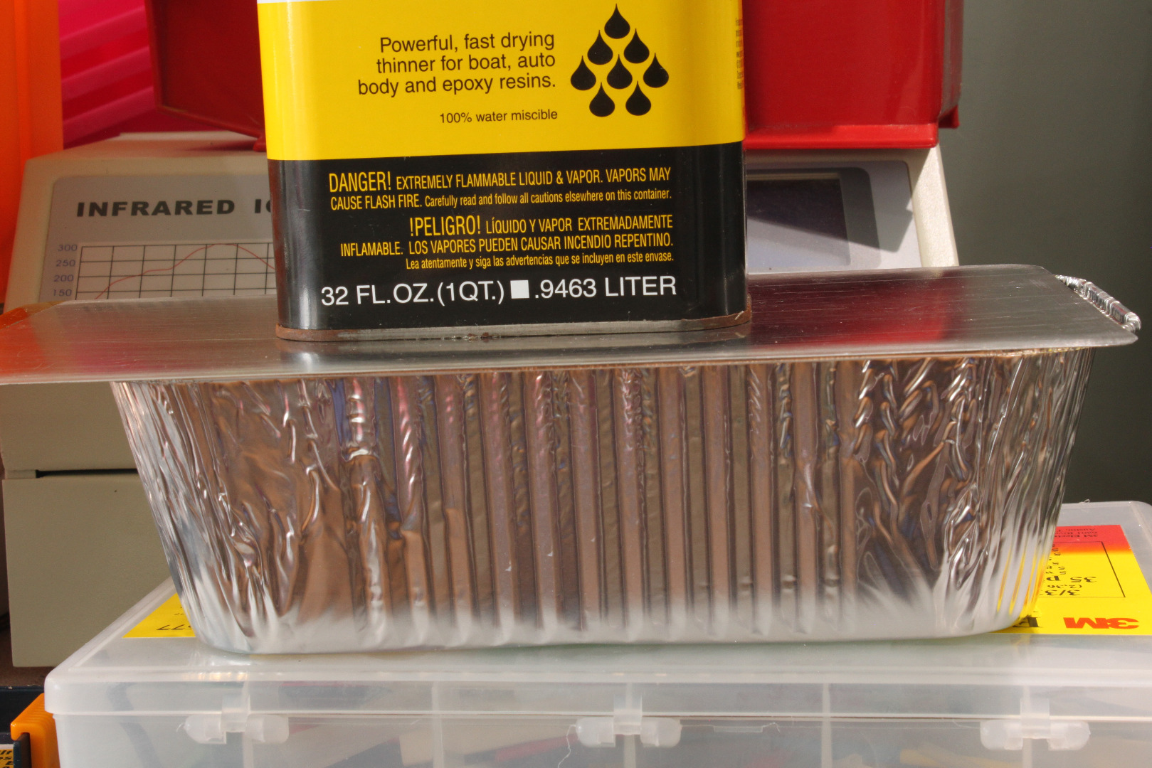
As printed, the line will adhere to the Carrier very tightly, but will easily be wiped off with a paper towel. To "fix" it in place will suspend it in acetone vapor. In a well ventilated area pour a small amount of acetone into a glass baking dish or an aluminum foil "loaf pan" that is at least 8 inches long. Lay the Carrier on the top, print down, facing the acetone. Put a small weight on top to help seal the carrier to the dish. Leave it there 10 minutes, then allow the Carrier to air dry for a few minutes. This fixes the toner firmly to the Carrier. Should you ever need to remove or reprint the cross, just wipe it down with acetone and it will come right off.
Making a Print
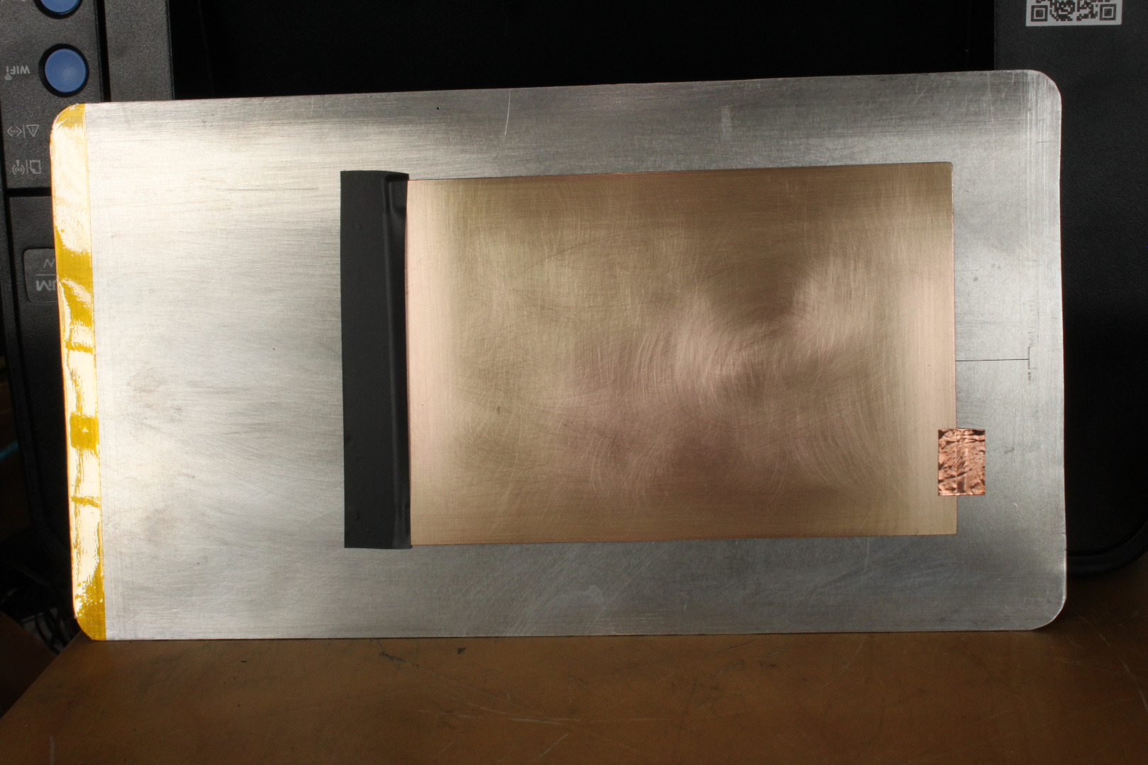
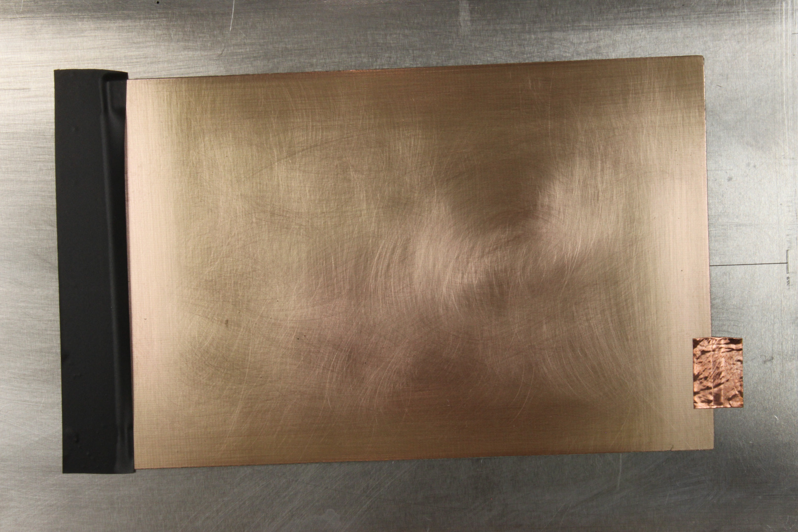
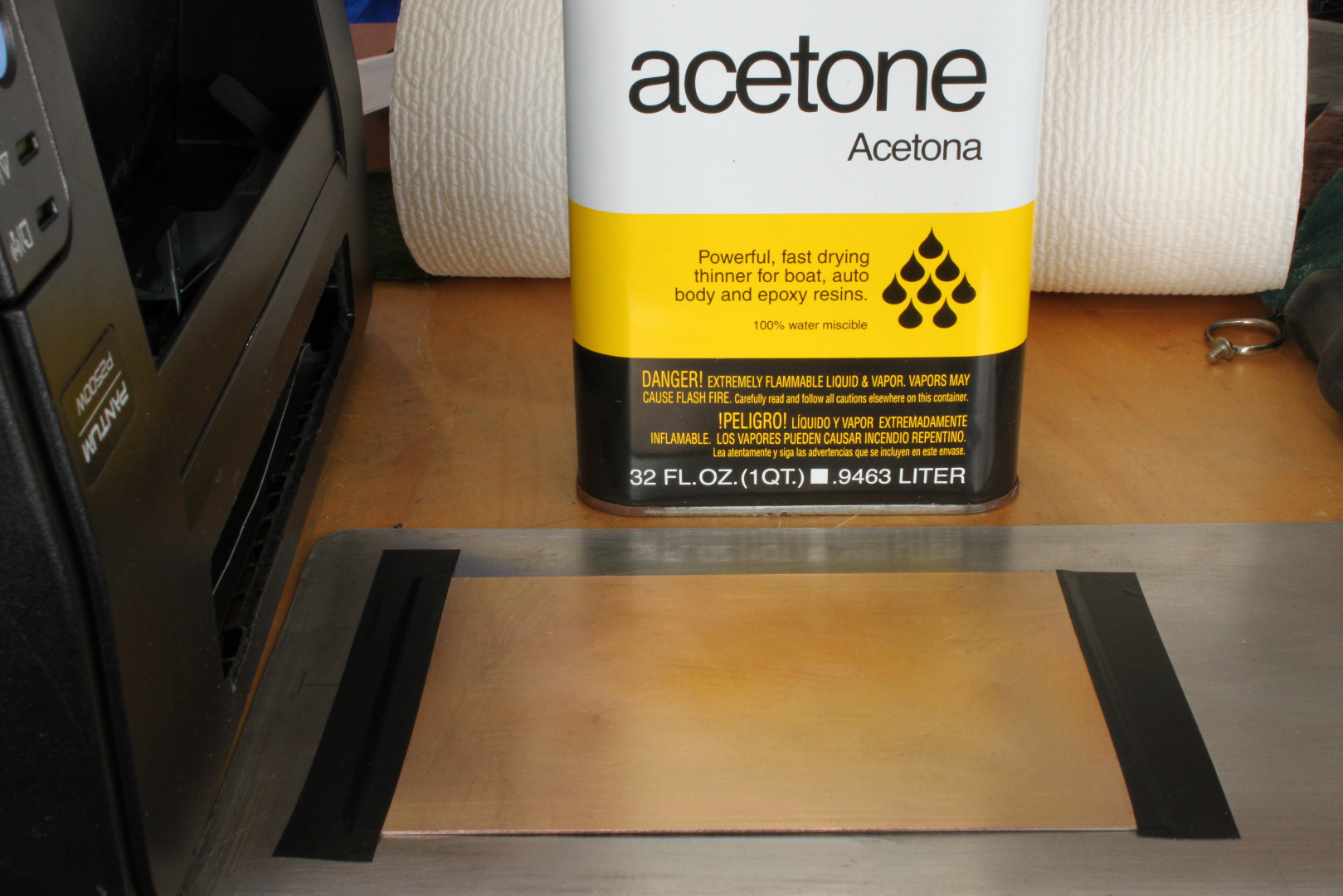
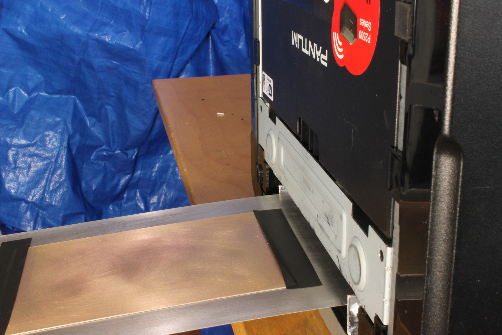
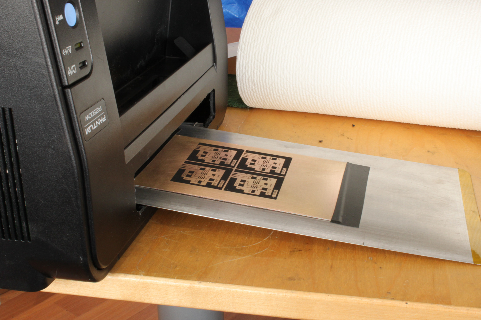
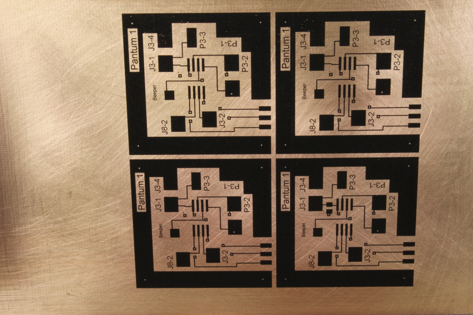
For this printer to work properly, PCBs must be FLAT as they pass through the printing interface. For thin PCBs that is no problem because they will be flattened by the Drum. For .062 PCBs you must flatten the PCB before using it. Try bending it against the "bow" till it is flat.
To make a print:
Turn the printer on. It will do a 5-10 second or so boot routine ending with the Ready LED lit.
Then,
1 - Lightly sand or file the edges of the PCB so that they will not damage the drum as the PCB goes through the printer.
2 - Clean the PCB with a Scotch Brite Scouring Pad then wipe with acetone on a paper towel till the paper towel comes off clean.
3 - Mount the PCB to the Carrier using a small piece of .25 inch wide copper foil tape to connect the upper surface of the PCB to the Carrier. This can be done on either the leading or trailing edge of the PCB. Be sure the copper tape has conductive adhesive - not all of them do!The PCB should be located at the top of the cross, centered on the Carrier.
4 - Cover the leading and trailing edges of the PCB with .75 inch wide vinyl electrical tape, attaching the PCB firmly to the Carrier and covering the copper foil tape. If necessary, you can now do a final clean with acetone.
5 - Slide the Carrier through the NPIS, above the Carrier Supports, and between the Lateral Paper Guides.
6 - Advance the Carrier till it reaches the Drum, then back it off about .25 inches. When you make the Carrier you should mark this position so that you don't actually have to hit the drum in this step.
7 - Set the top margin for your print to be about 1.5 inches, select 1200 dpi in "Printer Preferences". You will have to experiment with your printer settings to get maximum density and resolution, but the process isn't at all fussy.
8 - Click "Print" on your software.
9 - You will hear a "Beep" from the piezo beeper on the MCU board.
10 - After about 3.25 seconds the beep will stop. This is the start of your "timing window".
11 - Quickly but gently slide the carrier forward till it is engaged by the Drum/Transfer Roller Interface, then release. It is now printing! Do NOT jam it forward - you will foul up the timing!
12 - Remove the PCB from the Carrier, then suspend in in acetone vapor for 10 minutes to "fix" the toner to the copper.
13 - Etch in your favorite etchant.
14 Remove the toner with acetone on a paper towel.
If you mistime it and the printer errors out, open the Door and remove the Cartridge. Then remove the Carrier and replace the Cartridge. This prevents damaging the Drum.
Wipe the PCB with acetone if any toner got on it during the aborted run, then turn off and reboot the printer.
Conclusion
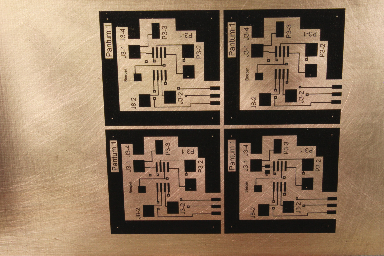
The Pantum 2502W is a very inexpensive alternative to the Lexmark E260 for DLP PCBs. It works well and takes up much less space on your workbench. Over the next few weeks I will experiment with double sided PCBs following the steps outlines in my previous Instructable, but I have no reason to believe it will not work as well.
Enjoy!
As always, if you have comments, questions, or concerns, you are welcome to contact me directly at <mlerman@ix.netcom.com.