Modelling a Self Watering Planter in Tinkercad.
by theinstructablesdude in Workshop > 3D Design
945 Views, 1 Favorites, 0 Comments
Modelling a Self Watering Planter in Tinkercad.
.png)
In this instructable I'll be showing you how to model a self watering planter in tinkercad. My printer is temporarily out of comission so i can't print it now, but i can still show you how to model.
You'll need:
1. a computer with wifi
2. That's it!
(and a 3d printer i guess)
The Pot
.png)
.png)
.png)
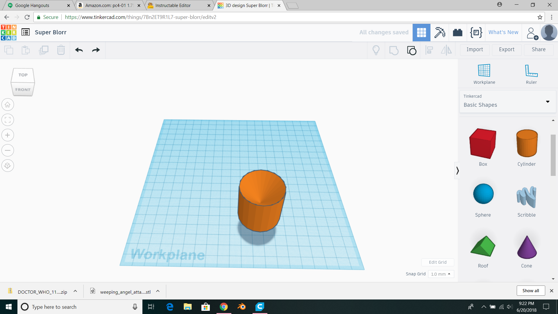
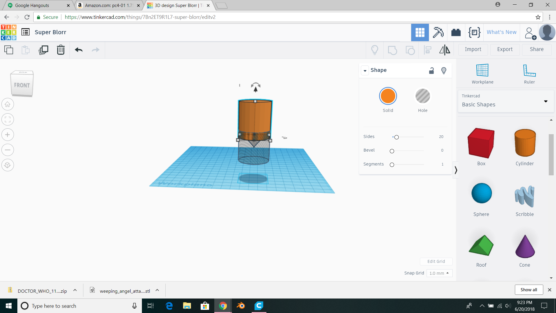
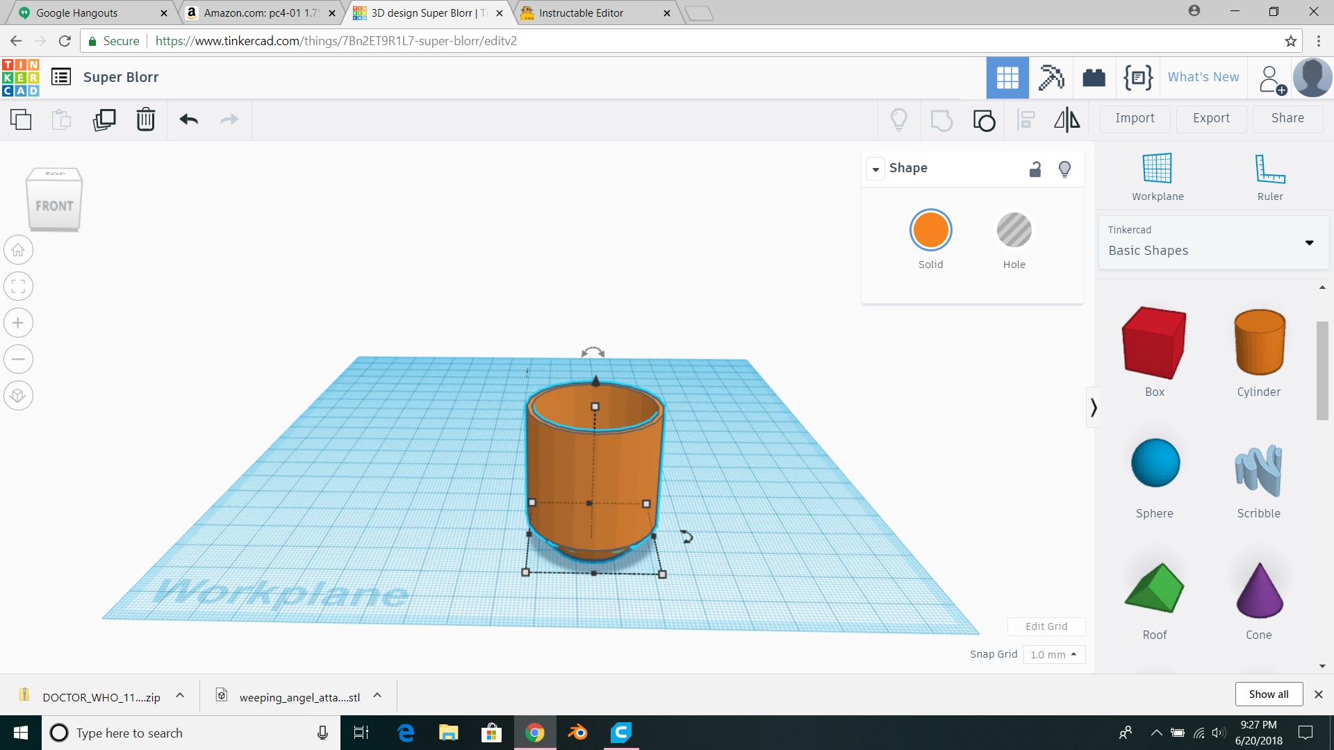
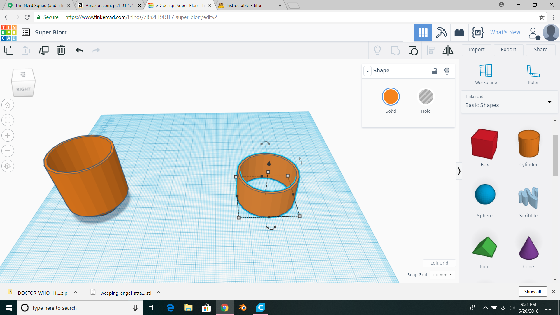
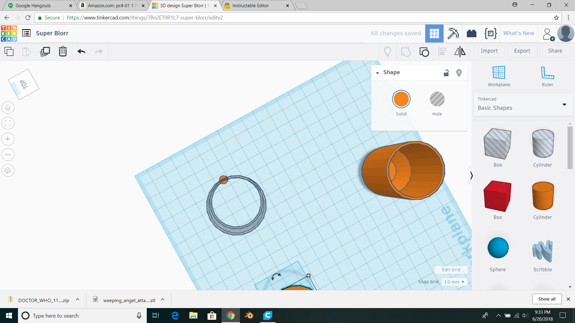
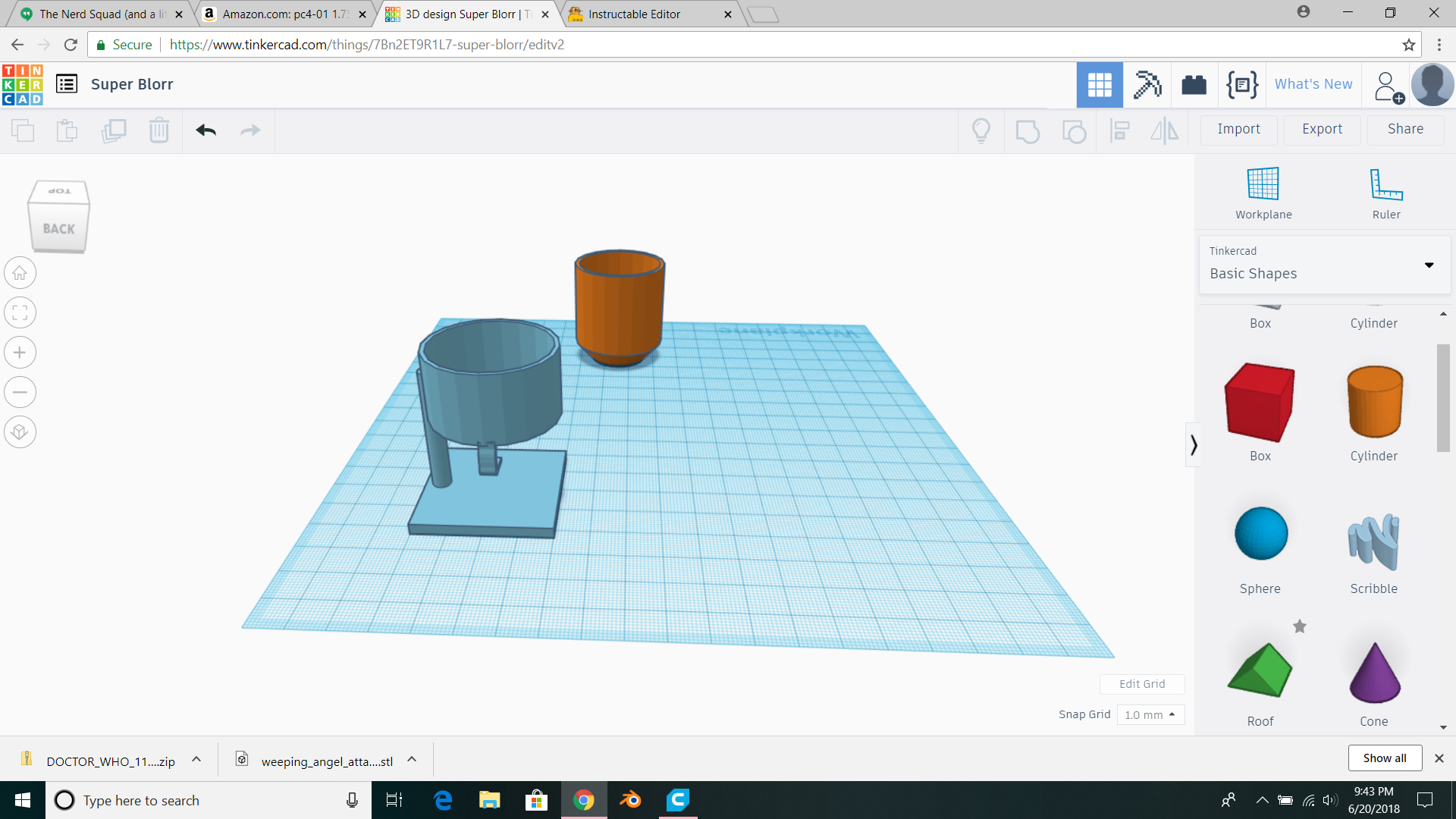
You can (should) buy a ceramic pot, since I'm just doing concept modelling I'll just model one. Start with a cylinder. 35x35x35mm. Make a cone 35x35x20, turn it into a hole, place it level with the top of the cylinder and group them. Then make another 35x35x40 cylinder, position it 8mm fro the top of the first and make the first into a hole as seen in picture 2. Then group them. Duplicate this final shape, move it over, scale it down by 2mm on each of height width and length, move it up 2mm, make it a hole, put it in the first one and group them. The final pot should look like picture #3. That's it for the pot. set it aside and we're moving on.
Stand for the Pot.
.png)
.png)
.png)
.png)
.png)
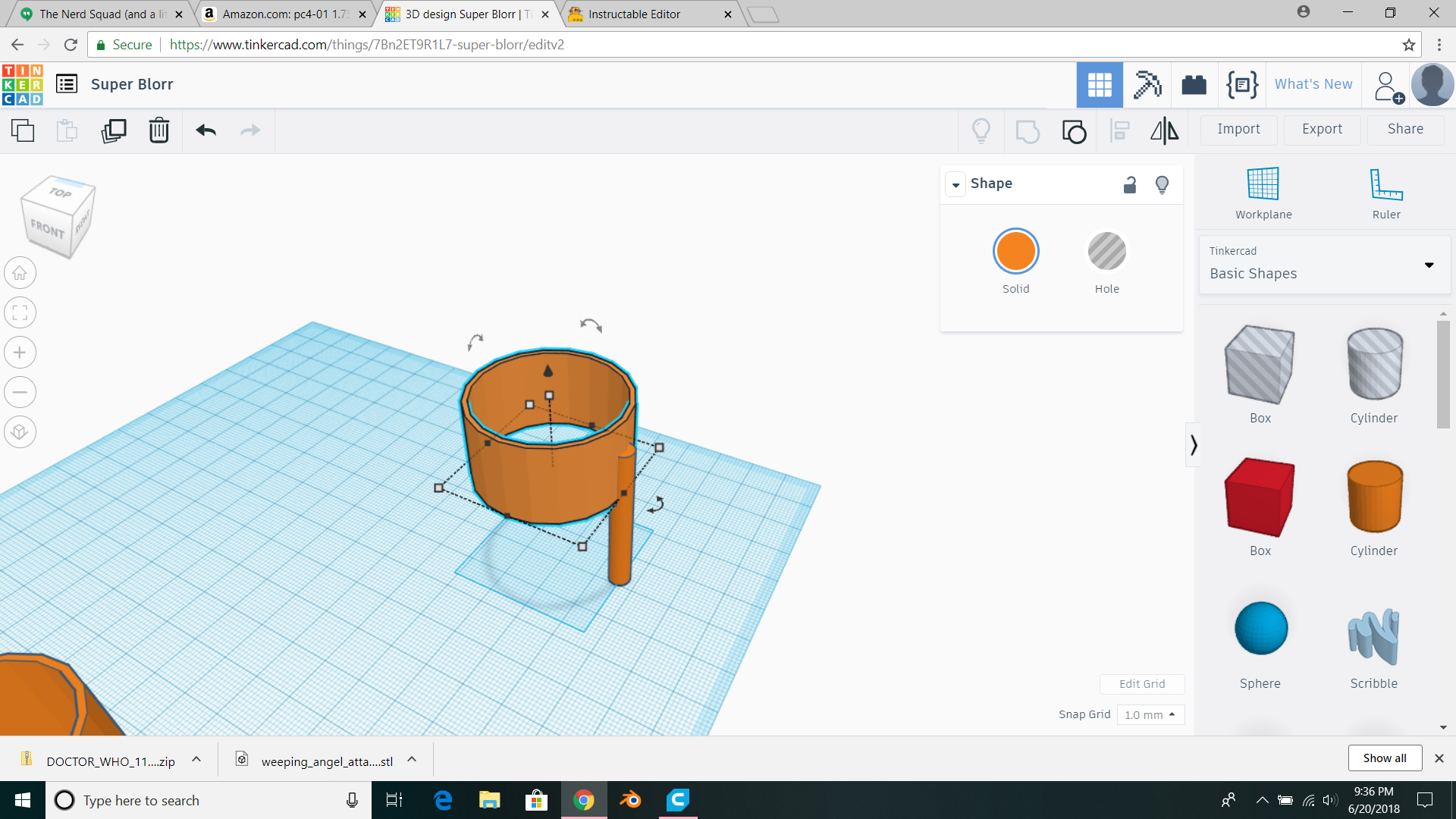
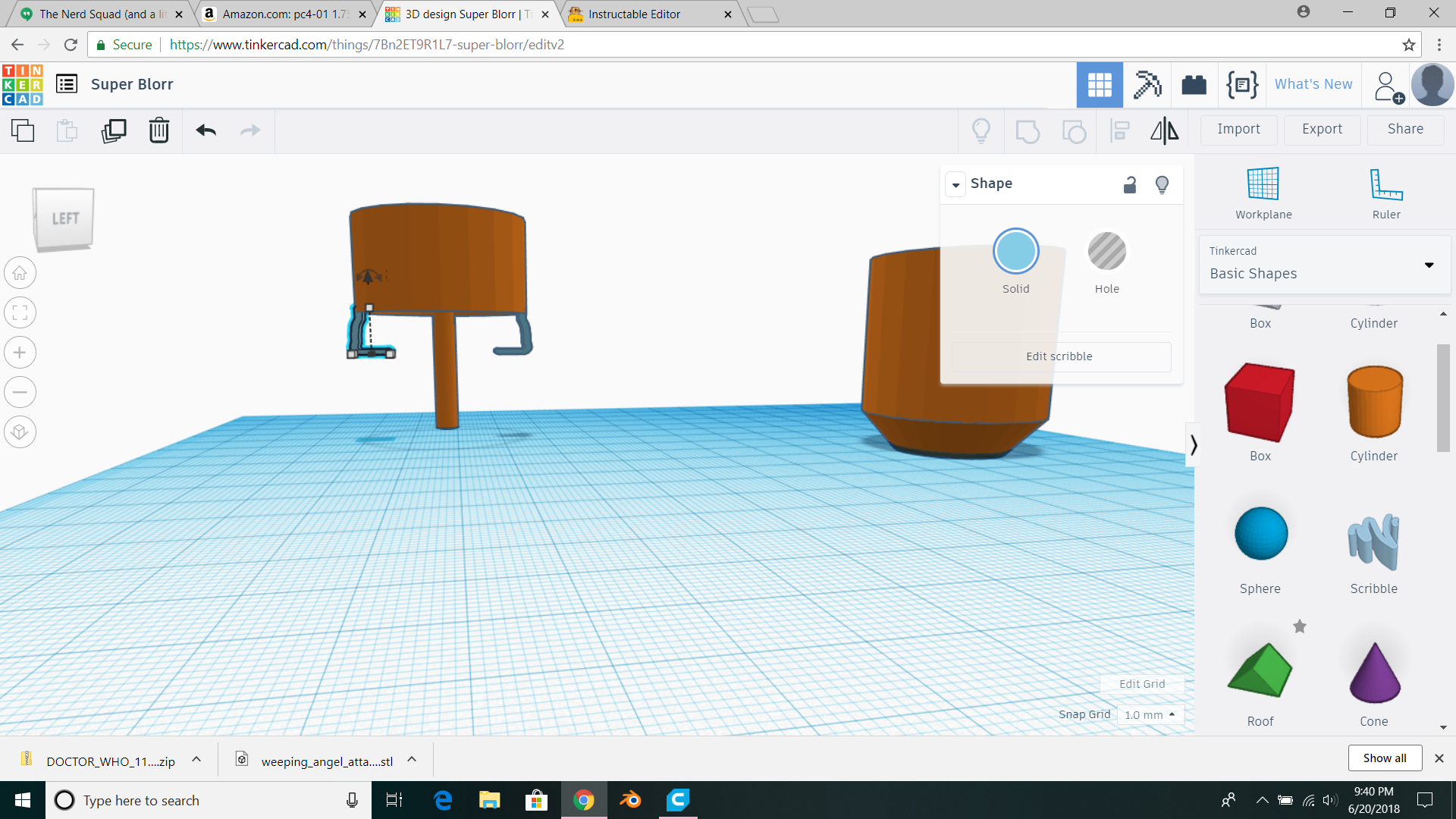
Make a cylinder, 37x37x20, then another 35x35x20. make the second one a hole, put it in the middle of the first one and group them. It should look like picture #1. Duplicate it, make one of them a hole, and group it with a 5x5mm cylinder as seen in picture #2. Then group them. You should now have a connector tube to the stand. Increase its height to 40mm and line up the original stand with it on top, like picture #3. Now we need to make a scribble. Make a rough "L" shape and scale it down to 10 length, 6 width and 4 height. Now take the L, and position it Directly under the stand at a 90 degree angle from the connector, aand another one mirrored on the other side as seen in picture 4. Then we want to group the whole stand so it stays together. Now make a 40x40x3mm base (a box) position it at the bottom of the tube, and group it, like picture 5.
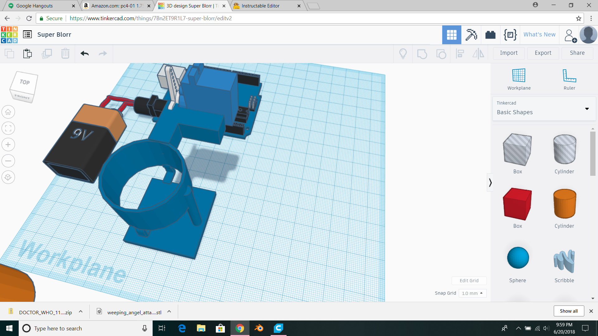
The Mechanism
.png)
.png)
.png)
.png)
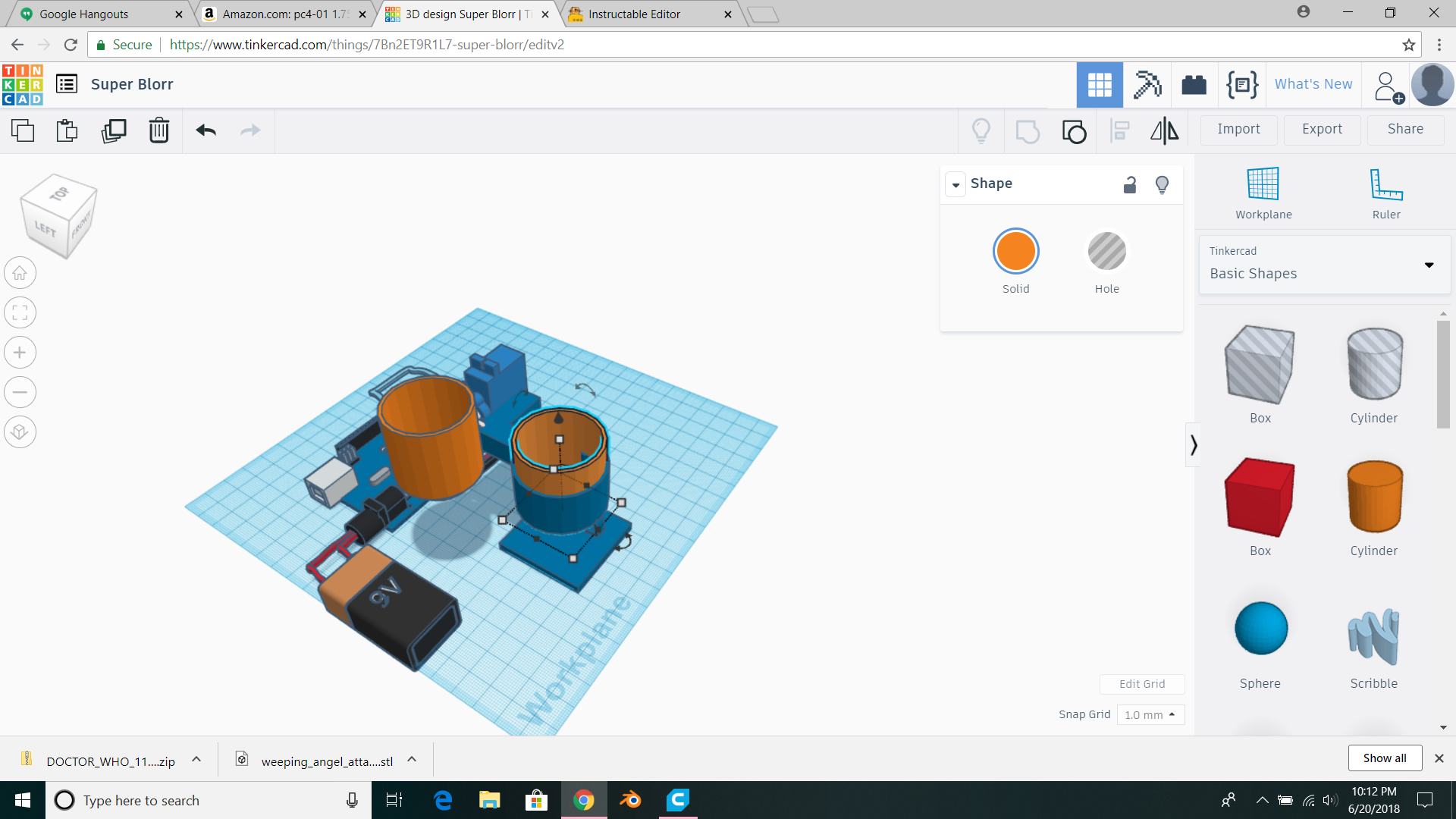
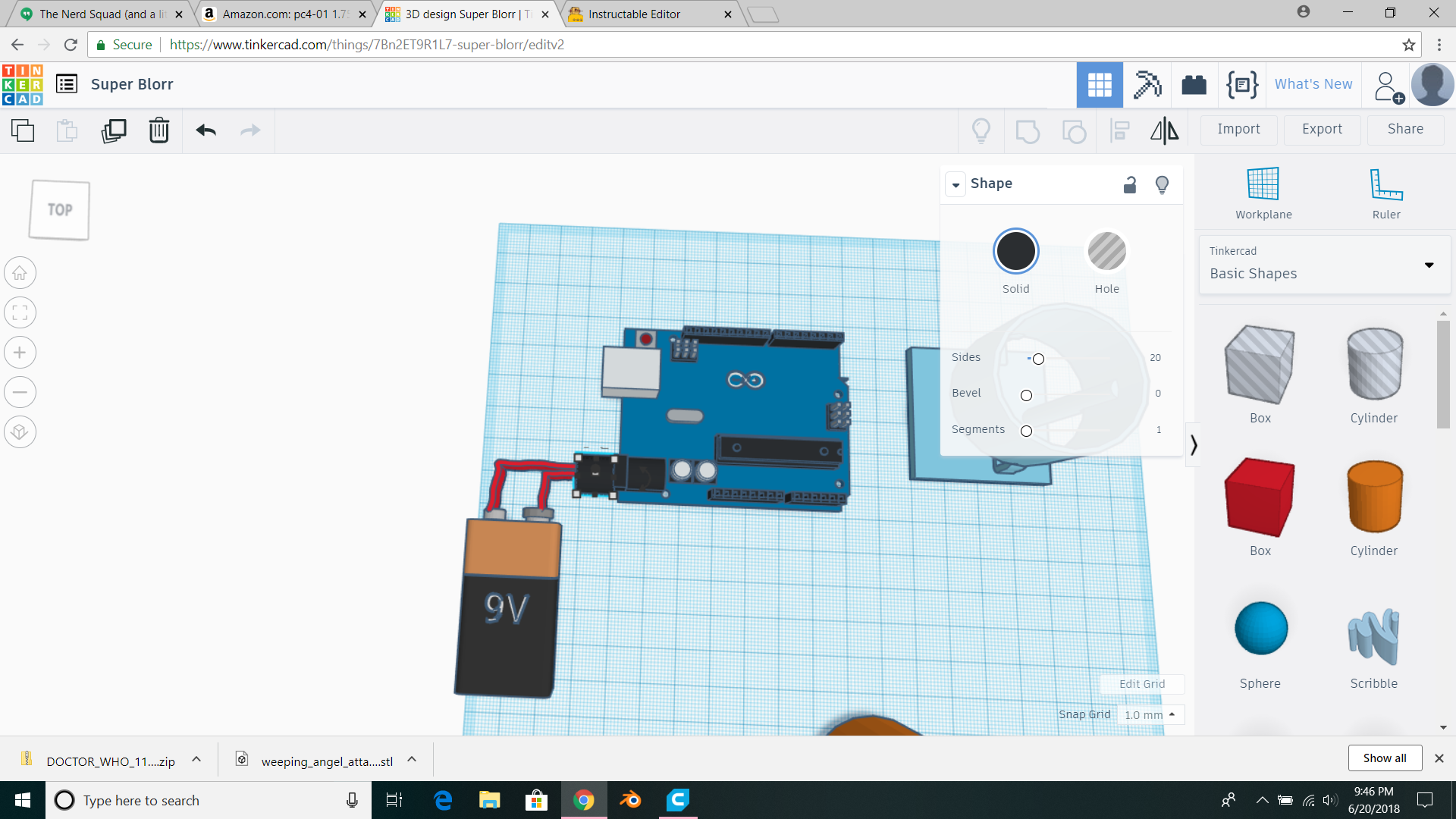
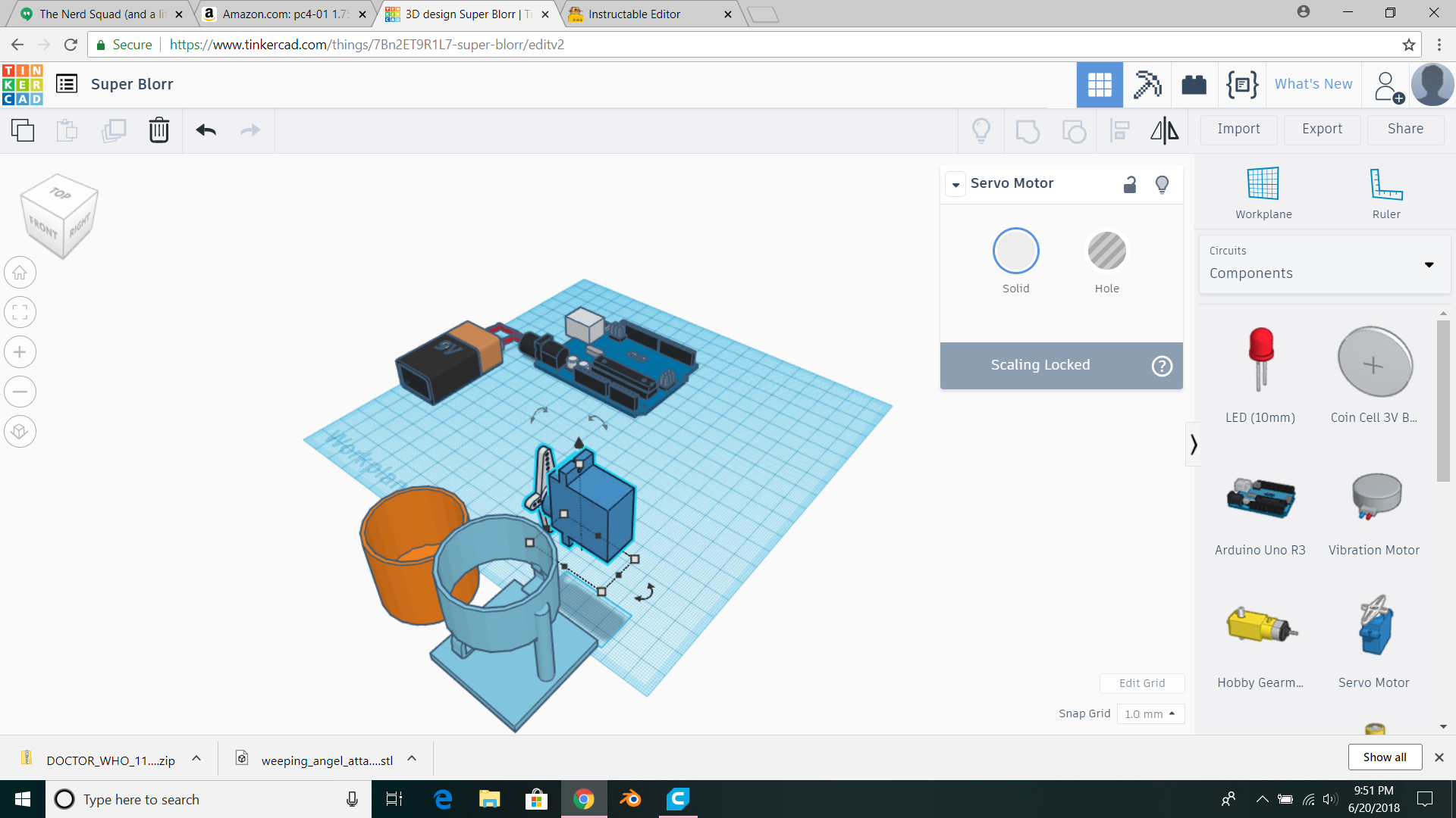
Remember, the pot and stand are both not to scale. Just remember that. scale them both way up if you're printing. I put an arduino (from components) next to a 9v battery and a connector made out of a scribble and a black cylinder, but that's not really important. Take a servo motor, move it over to the stand, rotate it so it looks like the picture 2. Not touching though. Make a 10x25x10mm box, and put it level with the middle of the servo and at the same time touching the stand. Now make the servo a hole and group it with the box. It should look like pic#3. now group that box with the stand. Now put the motor back, and make another box, same dimensions, but put it lined up with the first parrallel to the motor and group it. (pic#4) If you do print this the motor will be super/hot glued to this piece. A cup of water will be connected to the end of the servo, and you'll have to code it to in the morning (and at night) turn so it spills some water into the plant.
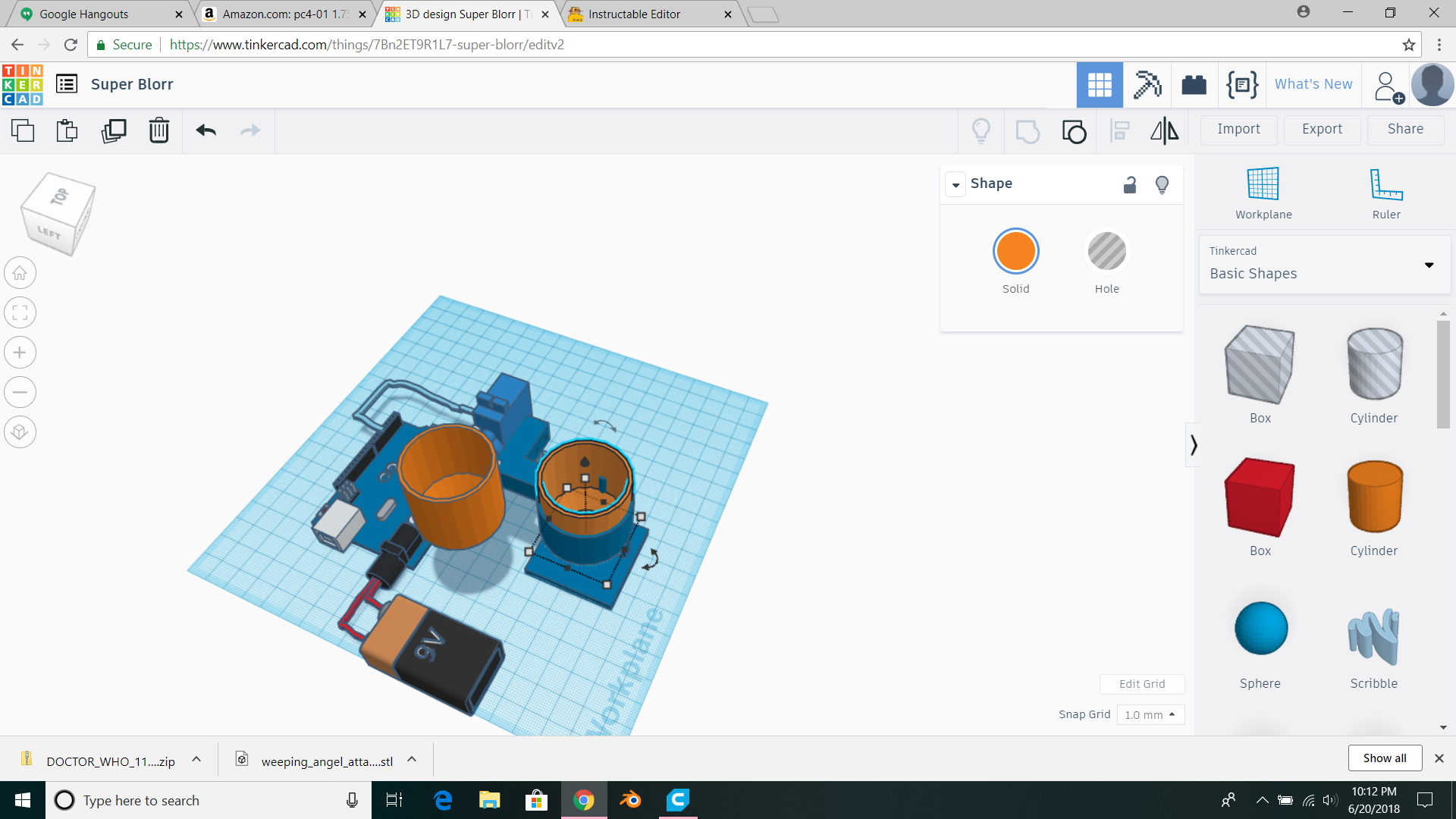
Final Assembly
.png)
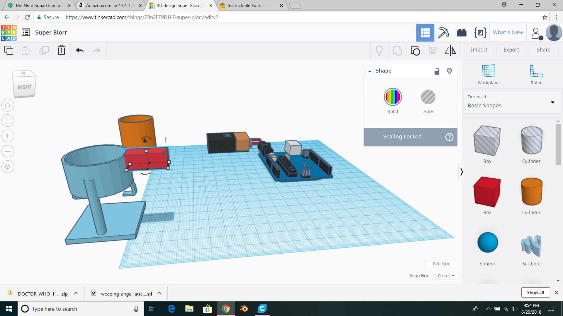
I just made some scribbles to be wire connections and duplicated the pot for a cup of water. Please bear in mind this is a 3d concept drawing nothing more. There are several major flaws, but it's just a drawing.