Mobile Steering Wheel Workstation for 04-08 Acura TL
by maxevets in Workshop > Cars
199 Views, 0 Favorites, 0 Comments
Mobile Steering Wheel Workstation for 04-08 Acura TL


Problem Definition and Design Requirements:
When I was growing up, my brother and I were constantly late to all of our practices and lessons. As a consequence of all of the anxiety this caused me, I have developed the habit of leaving the house way too early or showing up to something long before it starts. All too often I have found myself in between places, waiting in my car, feeling as though I am wasting time. Sometimes I am near a place where I can get out and find a place to do some work before my commitment, but other times, the most available and convenient place to work is in my parked car. Though my seat is comfortable and the cabin is air-conditioned, it is difficult for me to do work that requires a flat surface (i.e. anything with paper and pencil). A binder on my lap is not enough of a working surface, and even work on my laptop can be uncomfortable.
To resolve this issue, I have chosen to develop a multi-purpose workstation tray that attaches to my car’s steering wheel. This design would create a flat, steady working surface that allows me to enjoy the comfort of my driver’s seat while in between places. It would also function as a place to enjoy a meal or do whatever else might be convenient for me. Additionally, this will have an attachable phone holder, so that I am able to do things like join meetings and watch videos without encroaching on the work area. I will detail the design process first, but feel free to skip to the steps for the build.
Conceptual Design:
Once I decided that I was going to design a solution for my mobile workstation issue, I had to decide which features were most important to me. To do this, I utilized the functional decomposition method to make sure that the design I would work toward would satisfy all of my requirements and actually solve the problem at hand. Figure 1 details my first attempt at identifying the necessary functions as well as potential ways to design for these functions.
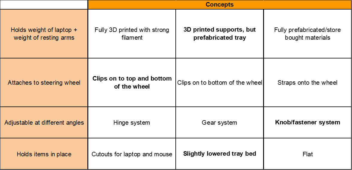
Figure 1: Initial functional decomposition matrix, with bold text indicating selected solutions.
I considered several different options for each function. The most important function by far was that the workstation could support the weight of my laptop and arms resting on it, as this was the crux of the design. It also needed to attach to my steering wheel, as the driver’s seat provides the most comfort in my car, so this would be the ideal place to work. I also initially wanted the tray to be able to adjust at different angles, but after more consideration, I realized that this was almost entirely pointless in terms of the scope of the work I was intending to use this workstation for. Finally, the tray needed to be able to hold the laptop or any pens or paper in place, so that if I were to knock it in any way, they would not roll off. This quickly became an essential function as I would already be working in a confined space, so bumping the workstation would be expected. It could also be expected that any pencil or utensil that might have fallen off of the tray could very easily be lost under my seat. Though this at first just seemed like a nice feature, I made sure to make it an important part of the design.
With the criteria for functionality set, I down-selected the concepts that made the most sense to me. I decided that 3D printed parts and prefabricated materials would result in the ideal design, as this would allow me to design the supports that are attached to the steering wheel custom to my car’s wheel. Having a prefabricated tray would also allow me to not worry about the material strength of a 3D printed item that needed to bear a load and would allow me to focus on strengthening the supports. Below, Figure 2 shows the rough draft of the initial design, where I would 3D print supports that would clamp around the wheel.
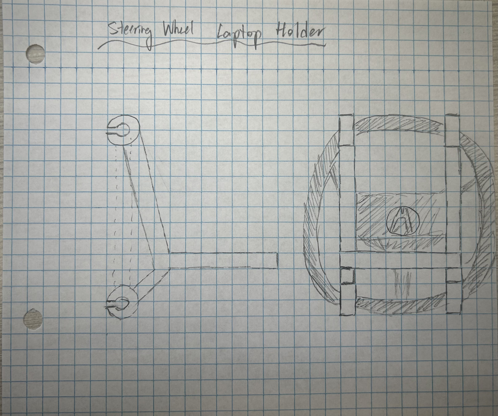
Figure 2: First sketch of design concept, showing the proposed top and bottom clamps.
I began messing around with designing this on SolidWorks, and I quickly realized that I was over-engineering the parts I was hoping to 3D print. As great as the top and bottom supports that clamped on sounded, I was adding too many features, like hinges that would open and close the clamps. This, coupled with a lot of issues with my 3D printer holding me up in the middle of the semester, caused me to reconsider my design, and I decided that the best course of action would be to instead reevaluate my needs in the project.
So I went back to the brainstorming phase, working through a new functional decomposition that reflected my needs and was kinder towards my timeline and capabilities. This was actually very productive, and I am very glad that I decided to pivot, as I began realizing that I could do more of what I wanted, far simpler than how I was initially trying to. Figure 3 details the functions of the newly designed mobile workstation. Most of the functions remained the same, but the concept selection differed. Now, the workstation would be fully made out of store-bought materials, as this ensured I would not be limited by my 3D printing capabilities and also helped me step away from over-engineering. The tray would now be supported by only a top set of supports, which would remove the bulkiness of the design and allow for more leg room. Finally, the tray-angle adjustability function was replaced with a function I thought to be more pressing, a place for my cell phone to be set. This would allow me to have hands-free video chatting or watching while I could take notes simultaneously.

Figure 3: Updated functional decomposition matrix, with bold text indicating selected solutions.
Detailed Design:
To now effectively start the redesigning process, I had to take a step back and create a plan. I first went and took a lot of measurements of my car cabin. This was to get a better idea of the physical limitations of my space when I am sitting in it. I used these measurements to begin deciding on the measurements of the tray table. I was able to set boundary conditions this way, as I knew that the minimum surface area of the workstation had to be slightly larger than the dimensions of my laptop and the maximum surface area could not extend into my chest in a seated position. I decided that a 10” depth by 14” width surface would allow for space for my laptop and for space to breathe.
With that squared away, the next major design function to tackle was the support that would attach the tray to the steering wheel. I began brainstorming ideas of how I could do this beyond my initial clamp idea. I considered using rings that open and close around the wheel, with string/cable lines attaching to the four corners on the top of the tray. I realized that this design was too messy and would impede on the working area in too significant of a way. I then started to look into different types of hooks that could easily hook on and off of the steering wheel. I particularly began looking on McMaster-Carr for pegboard hooks and other hooks with pre-existing mounting hardware that I could repurpose to attach to my tray. I decided that this was my best option, and I went to Home Depot after more research and found the perfect set of hooks with mounting hardware for my design. I bought a heavy-duty flip-up storage hanger that could be used to mount bicycles and other tools on walls. It featured a wall mount with two protruding hooks coming out, as shown in Figure 4. To utilize this in my design, I would flip it, attaching the hooks to my steering wheel and my tray to the wall mount. I measured the distance between the hooks, verifying that it would fit to my wheel, and I tested it in the parking lot afterwards.
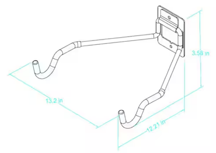
Figure 4: Dimensions of the Husky “Heavy-Duty Flip Up Storage Hanger”
While at Home Depot, I also picked up a piece of quarter-inch thick 12” by 18” MDF (medium-density fiberboard). It was a cost-effective option that would be easy to work in conjunction with the hanger. With all of this complete I was able to begin the process of assembling my design. This is detailed in the steps below.
Supplies
- 1/4 in. x 12 in. x 18 in. Medium Density Fiberboard
- Heavy-Duty Flip Up Storage Hanger
- 1/4-28X1/2 Phillips Flat Machine Screw Fully Threaded Zinc
- 1/4-28 Fine Thread Finished Hex Nut Grade 5 Zinc
- PLA 3D Printer Filament, 1KG 1.75mm
- Cricut Cuttables Adhesive Backed 3 Mil Vinyl Chocolate Brown
- Safety Glasses
- Hand Drill with pilot hole bits
- 3/32" Countersink drill bit
- Phillips Screwdriver
- Table Saw
- Utility Knife
- 90° Woodworking Angle Rule
- Wood Glue
- Pencil
- 3D Printer
- Computer that runs SolidWorks and Cura (if modifying build)
*Note: These are just the items I used for my particular build. Do not feel limited to using these, I just had most of these on hand already.
Sizing and Cutting the MDF


I needed to cut my MDF down from 12" x 18" to 10" x 14", so I used my 90° angle rule to pencil my cuts, then I used a table saw to cut it down. Then, to create the lowered tray bed effect, I marked and cut the remaining scrap MDF to create a trim that rests on top of the tray. This will keep pencils and other utensils from falling.
Conducting a Test of the Support


Though the wall hanger mount is rated for 50lbs, we will not be using the accompanying screws. Instead, I will use a flat ended screw that will not stick out and poke/cut my legs when I am sitting. In the shop, I had a 1/4-28X1/2 Phillips Flat Screw and an accompanying nut that I found to be a perfect fit for the mounting hardware. So, I proceeded to take a flimsier scrap board that I had on hand that was a similar thickness to conduct a test of the mounting hardware paired with a board. I drilled a few pilot holes first, then used a 3/32" Countersink drill bit to drill my hole. I screwed in the screw and attached the board. I had my brother hold the rig in the position it would sit on my steering wheel, and I rested my laptop on top of it (pictured), as well as a heavier book I had on hand. The flimsy board passed these tests, and I took it this test rig apart.
Attaching the Supports


Next, I marked the center of the MDF board so that I could properly center the support hanger. This ensures that any load applied is evenly distributed across the two supports. Following the same process as Step 2, I screwed the screw in until it was level with the work surface, attached the nut, and my rig was complete. I tested it with the laptop, and it was once again a success.
Gluing on the Trim


Finally, I used wood glue that I had on hand to glue down the trim. It is not necessary to do this next tape, but out of good practice, I used painter's tape to secure the trim in place while the glue dried (approx. 1 hour - just to be safe!).
Designing the Phone Holder Attachment


Now that I had a complete working workstation prototype. I needed to design the accompanying phone holder. I browsed on Thingiverse.com for some ideas, and then I finally settled on a design that would attach to the back end of the tray table. This design would hang over the tray table, allowing for the bulk of the work area to be usable so that one could do other things like take notes or eat while having the phone in hands-free mode. I took more precise measurements of my tray table with my caliper, and then designed to those precise dimensions. I added a long section on the bottom that would counterbalance the weight of the phone against the bottom of the tray in case the snug fit of the attachment was not enough to hold the phone in place. I utilized SolidWorks to design my part, then I saved it as an STL. I have attached the STL, part, and drawing files here.
3D Printing the Phone Holder


I then uploaded the STL file into UltiMaker Cura (but you can use any slicing software), to generate gcode that I could send to my 3D printer. I opted for the premade "Extra Fast" profile with .3 mm layer height, 0.84 mm wall thickness, 15% infill, 50 mm/s print speed, and brimmed bed adhesion. Having printed a phone holder before, I had a good idea of what would be able to support the weight of my phone. I oriented the print on its side, to minimize any overhangs or need for supports. The slicer indicated that my print would take just over 4 hours and use 95 grams of filament.
From there, I turned on my printer and started the print (make sure to level your bed and do all necessary upkeep before starting). After 4 hours, I had my phone holder prototype!
Assembling the Prototype - Final Step!


Finally, I added the finishing touches. I added a thin layer of vinyl that I cut to the size of the tray bed, to smooth out the surface and cover the screw. I then slotted in the phone holder to make sure the fit was correct. It fit in like a charm. This completes the build of my mobile workstation prototype!
Final Testing and Performance Evaluation

To conclude the physical part of this project, I wanted to use the prototype how it is intended to be used. I mounted it in my car, and I typed on my laptop with my arms resting on the keyboard. The prototype supported the weight. I also tried using my phone while taking notes, and everything from the angle of the phone holder to the ease of writing on the the surface worked well! The only major contention I have is that I wish I had used something thicker than vinyl to cover the screw hole. That one spot is a little bit difficult to write on, so in future iterations, I might opt for a thicker cut or some other material.
As an added bonus, the tray stows away nicely under my seat!
Estimated Costs and Manufacturing
To begin to round out this project, I created a spreadsheet with all of the costs associated with the project. I have attached that here. I did not factor in the cost of my time, but I spent between 75-100 hours researching, sourcing, building, and documenting this project.
If I were to manufacture this on a larger scale, I could buy all of the material in bulk at a reduced cost, or I could (with proper scaling), have a factory that assembles them. The MDF would be easy to buy in bigger sheets that are easier to cut in at once, but realistically, I would pivot to a lighter and more comfortable tray material, like a plastic of some sort. Similarly for the wall mounted hangers, I could either buy them in bulk, or I could manufacture them myself with the operation of heavy-duty metal-bending machinery. The hardware could then be altered to be screwed into the tray more seamlessly, and then this final assembly step could be done by hand with pneumatic drills.
Conclusion

I am very happy with the final working prototype that I have developed. I am even more happy with the learning I have gained from the utilization of the design process. Having to restart my entire design and rethink things entirely helped me to better understand what I wanted out of the project. This is also true for the research and building processes, where there were many things that went wrong/took longer than anticipated because it was my first time doing them. Though I mentioned it only briefly, I became intimately familiar with my 3D printer and troubleshooting it over the course of this semester, and without all of the hiccups I had with bed leveling, broke sensors, mismatched wiring, and much more, I would not have final prototype that I am nearly as proud of. Thank you for taking the time to read this guide! I hope this Instructable has been of some help to you, and if you have any questions, feel free to reach me at e.maxim@wustl.edu .