Mobile Full Charge Autooff
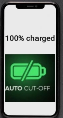
Mobile phone charging cutoff automatically when fully charged.Need not worry about battery life even if you had left it over night.Mobile phones are run by the batteries. Though batteries are handy to use, their use need some precautions too. A major problem with the use of batteries is their over discharging and over charging. Both of these issues affect the life of a battery and cost the end user needlessly. These issues are often ignored by the users too. The improper handling of batteries shorten their life .
In this project, the first thing I want to automate is “smartly charging” my smartphone to prolong its life: when the mobile battery is fully charged ( means 100% )it automatically stopS charging and cutoff the power from USB. The percentage of charging can be set as per our convenience. Battery level also can be set to for charging on.
In this tutorial I used ESP 8266 WiFi module with android automation tool Macrodroid app.Whenever battery percentage reaches 100%, Macrodroid triggers a command to web browser which issue a command to esp8266. Then digital o/p pin of ESP 8266 will cut off the charger supply from charger which is connected from RELAY.
Things You Need
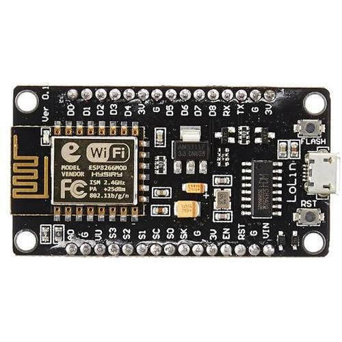
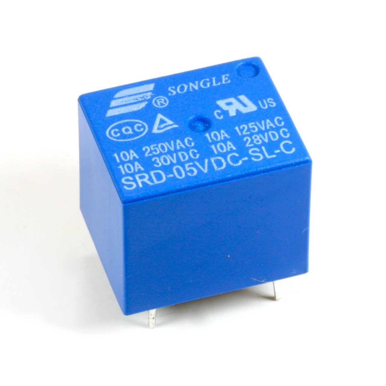
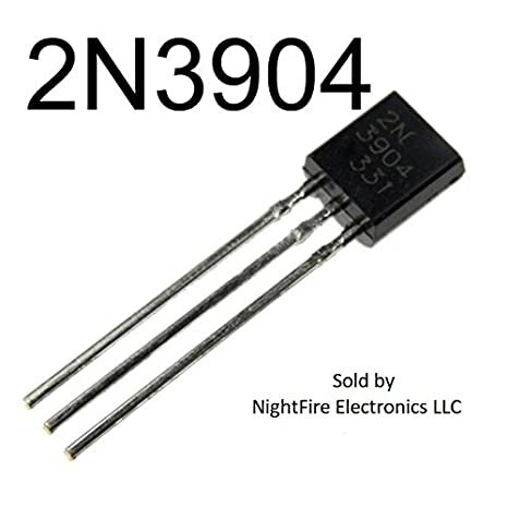
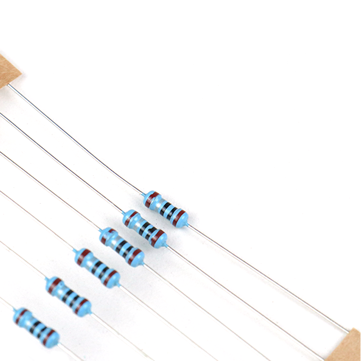
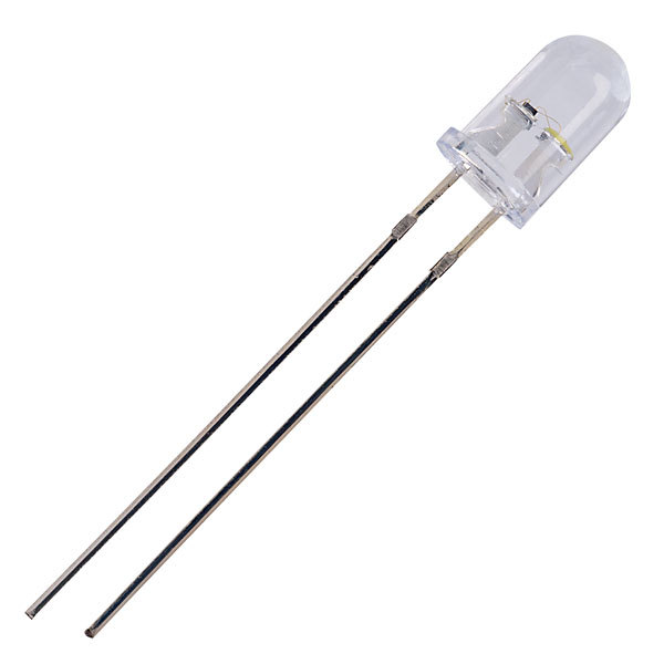
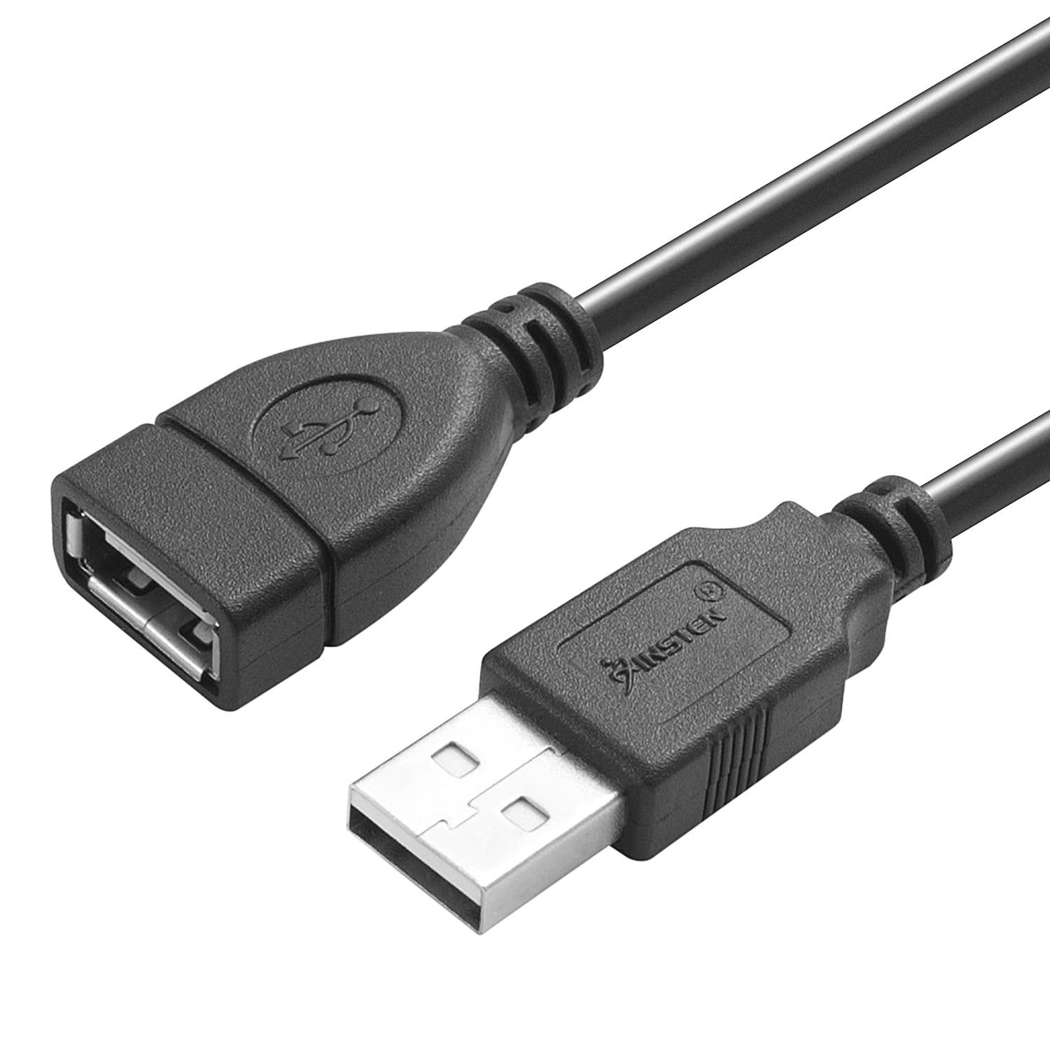
1.Node MCU-ESP8266 MODULE
2. RELAY 5 volts
3.NPN TRANSISTOR
4.USB MALE AND FEMALE CONNECTOR
5.RESISTORS: 1K ohm and 2.2K ohm
6.Three female jumper wires for wifi module
7. Small PCB
Circuit Diagram
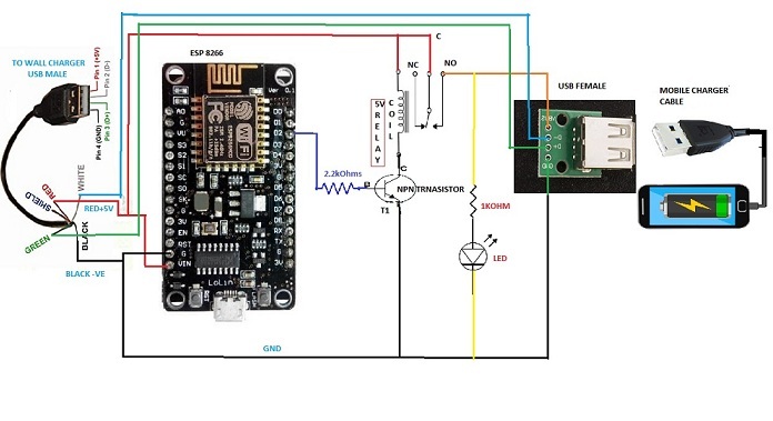
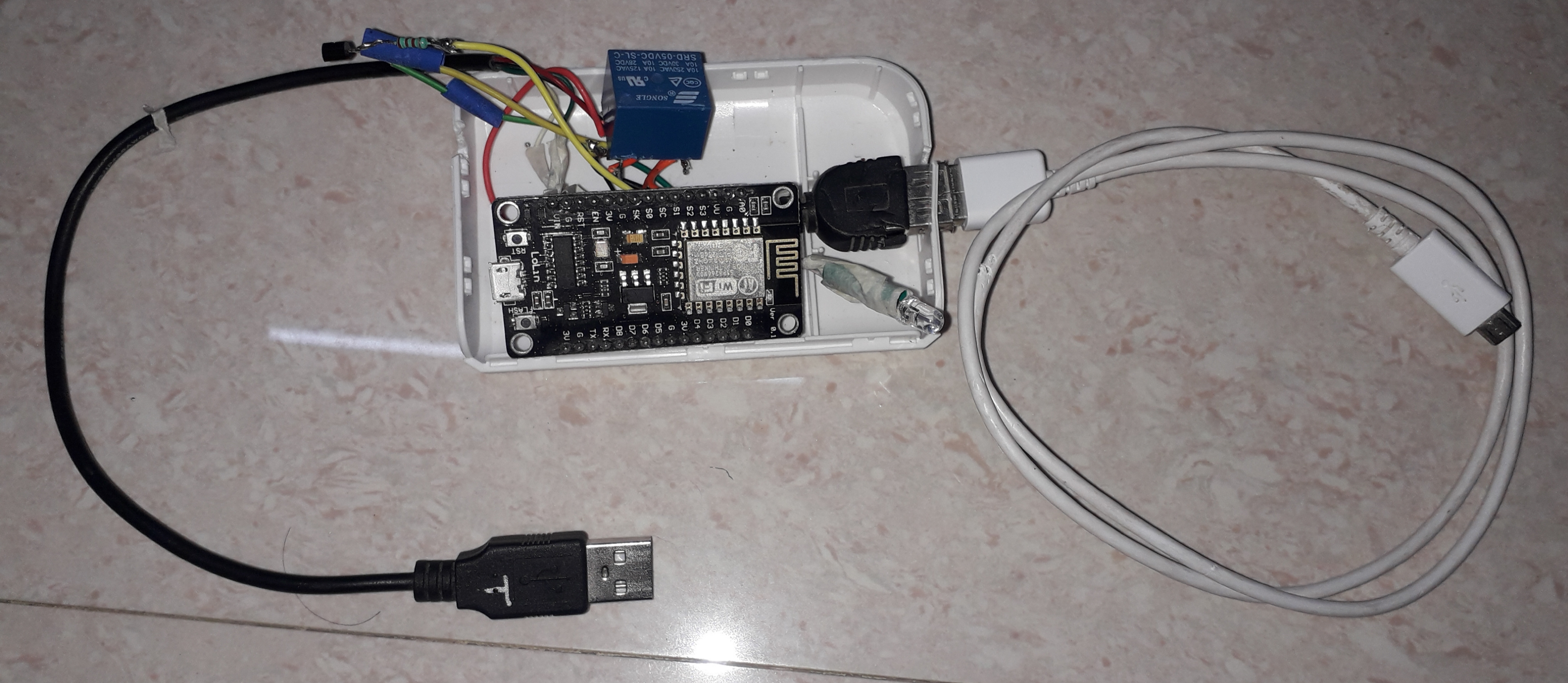
After uploading the sketch into esp module connect 5V from usb male (+Ve Red wire) to one point of Relay coil,Common point of relay and Vin of node MCU. Connect (N/O) of Relay to +ve of Female USB(Red wire).Connect second point of relay coil to Collector of T1(any NPN transistor).Connect base of T1 to D2 of node mcu through 2.2k resistor. Connect Black wire of Male USB (-Ve) to Female USB(Black wire), emitter of T1 and Gnd of Node Mcu. Connect LED +ve to N/O of relay and -ve to -ve through 1k resistor as shown in circuit diagram.
NOTE: USB Male to female connection wires should be short in length as voltage drop may occur in long wires.
How It Works
Initially D2 of Node mcu will be high and T1 is in conducting state and relay energize. Now Voltage will pass through relay contacts and Mobile will start charging. Node mcu Digital output is 3.3v only which is not enough to drive Relay so T1 is used in this circuit. Macrodroid APP is an Android automation app that continuously monitors the mobile charging percentage. As soon as charging reaches to set value ie.100% Macrodroid executes a URL command in web browser via Node mcu. Then D2 will go Low, T1 turns off and Relay deenergize, In this condition, supply will cut off to mobile and charging stops.
Code for Esp8266
I am using ESP8266 NodeMCU for controlling Relay.
When Node Mcu power is on, it connects with my home wifi network and it gives IP address - 192.168.0.115, and by that I can control my relay through Localhost. I am using the below link / url to control my application - 192.168.0.115/status 4=1 (for relay on) & 192.168.0.115/status4=0 (for relay off).
Note 1.# you can change digital output pins.
Note 2:# D2 of Node MCU is D4 of arduino in programme.
Clink link below to install Arduino main software in to PC
Install Arduino main software into PC
Clink below link for Installing ESP8266 Board in Arduino IDE (Windows, Mac OS X, Linux)
Installing ESP8266 board in Arduino IDE
This code works very well.
Download my code from this link:
Link:- Mobile full charge
Steps.
1.Connect esp8266 to PC through USB cable
2.install all libraries which are in sketch from github
Select>tools>Boards
Select>tools port
Open the above link and
change your home wifi SSID and Password in sketch, line numbers 6,7
change your wifi IP,Gate way,subnet.
To get IP,Gateway and subnet open control panel:
click on view network status and tasks
click on local area connection
click on details
IPv4 address is your ip address 192.168.0.XXX(xxx can be any number you can give on your own for URL in sketch line number 99) . I kept 115 [example: IPAddress ip(192,168,0,115)];
then upload the sketch.
Testing:-
Connect LED with 1k resistor ,+ve to Collector of T1 and -ve to GND
initially LED will be ON.
Note:You should give same URL number in web browser which you have given in Arduino sketch IP address Line number 99.
open new tab in Web browser and enter url http://192.168.0.115/status4=0
led will be OFF , again enter url http://192.168.0.115/status4=1 relay will energized andled will be ON.
You can enter this url on your mobile which is connected to same wifi network
if this works,then every thing is ok.
Now remove ESP8266 from computer and
Solder relay,led,resistors,transistors on small PCB.
I kept whole thing in old power bank chassis.
USB male to female wires should be short in length to reduce the voltage drop.
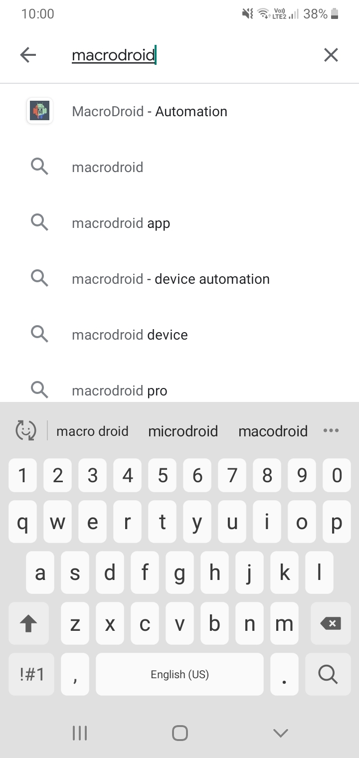
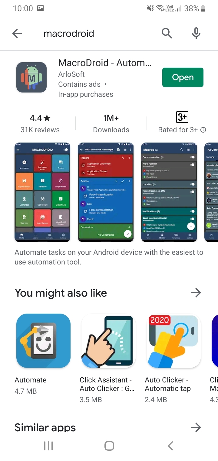
Go to Android Play Store and Search for Macrodroid App and Install It
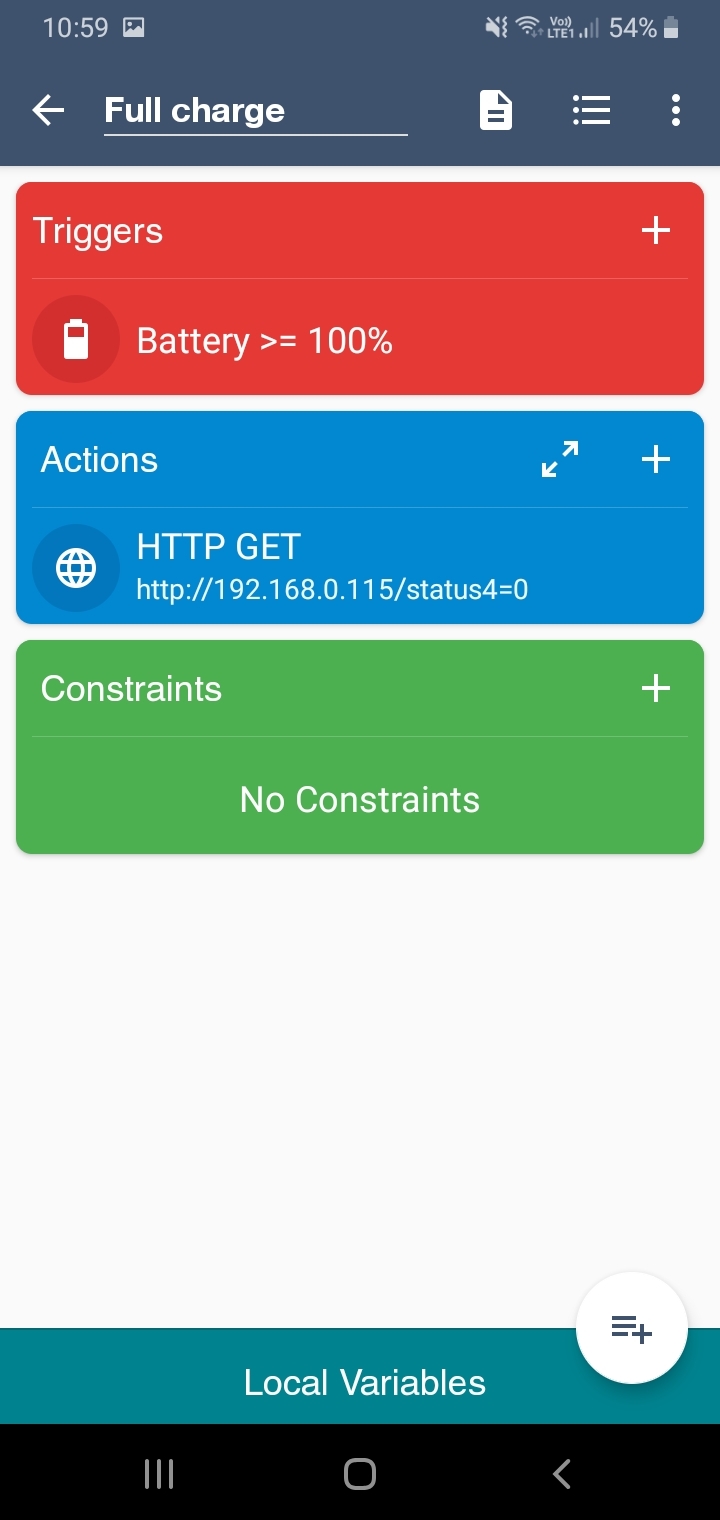
Open App and Press Add Macro
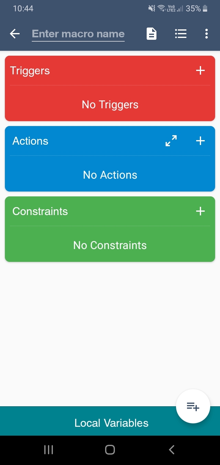
Press + on Triggers
Press on Battery/Power
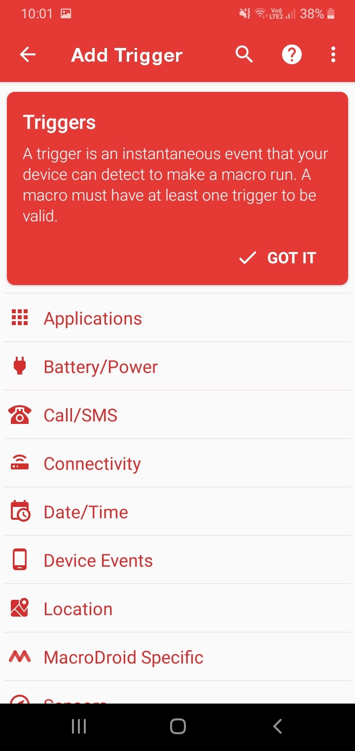
Click on Battery Level
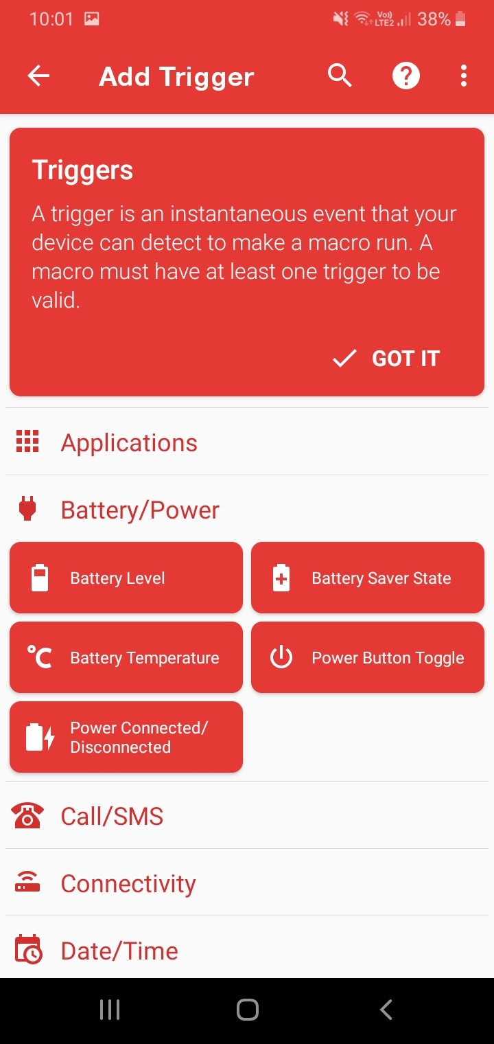
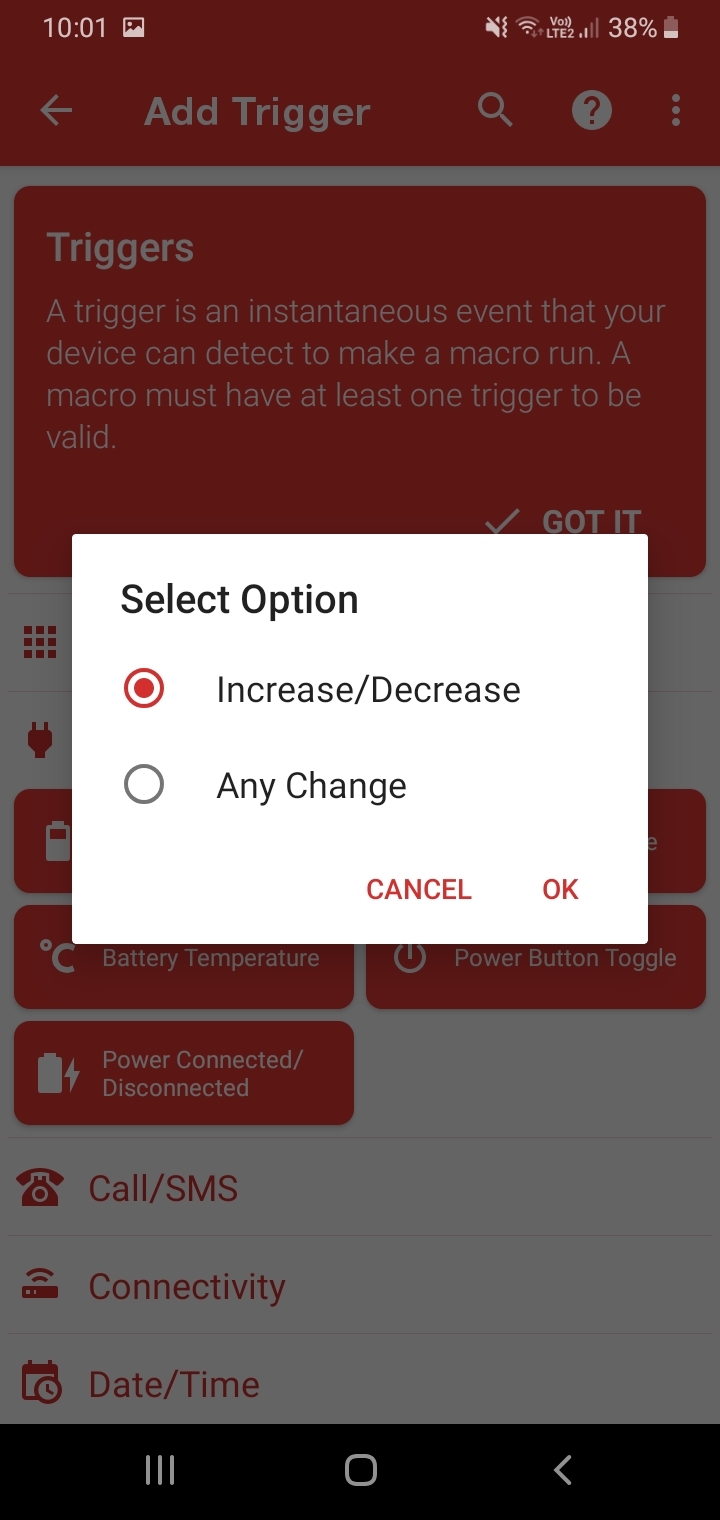
Select Option Increase/Decrease, Press Ok
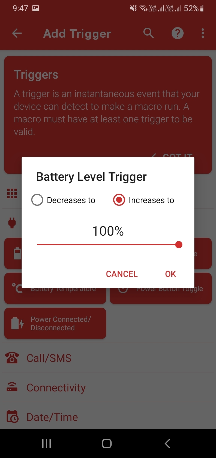
Select Increase to and Slide Bar to 100%, Click Ok
Select + Icon on Actions
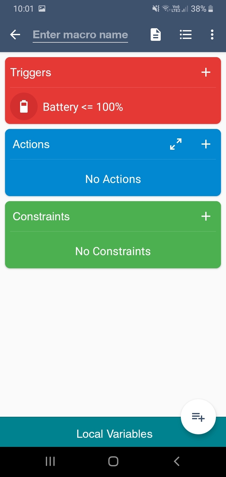
Select Applications
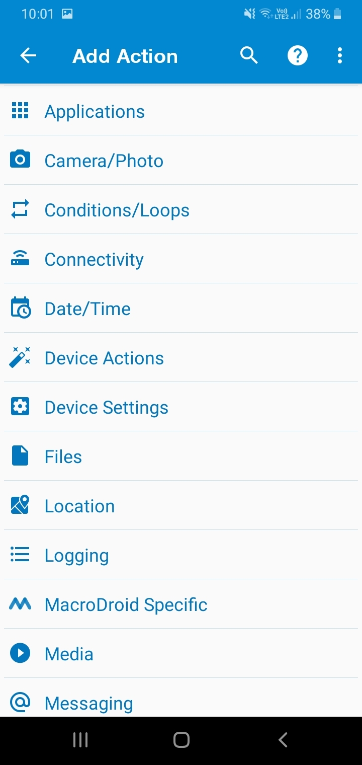
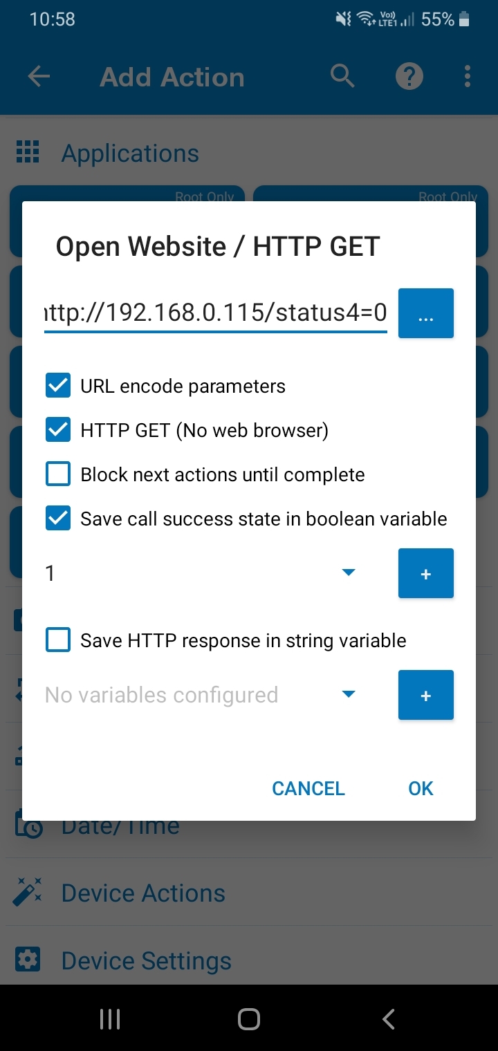
Select Open Website/HTTP GET
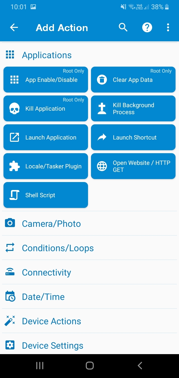
Enter Url Http:/192.168.0.115/status4=0
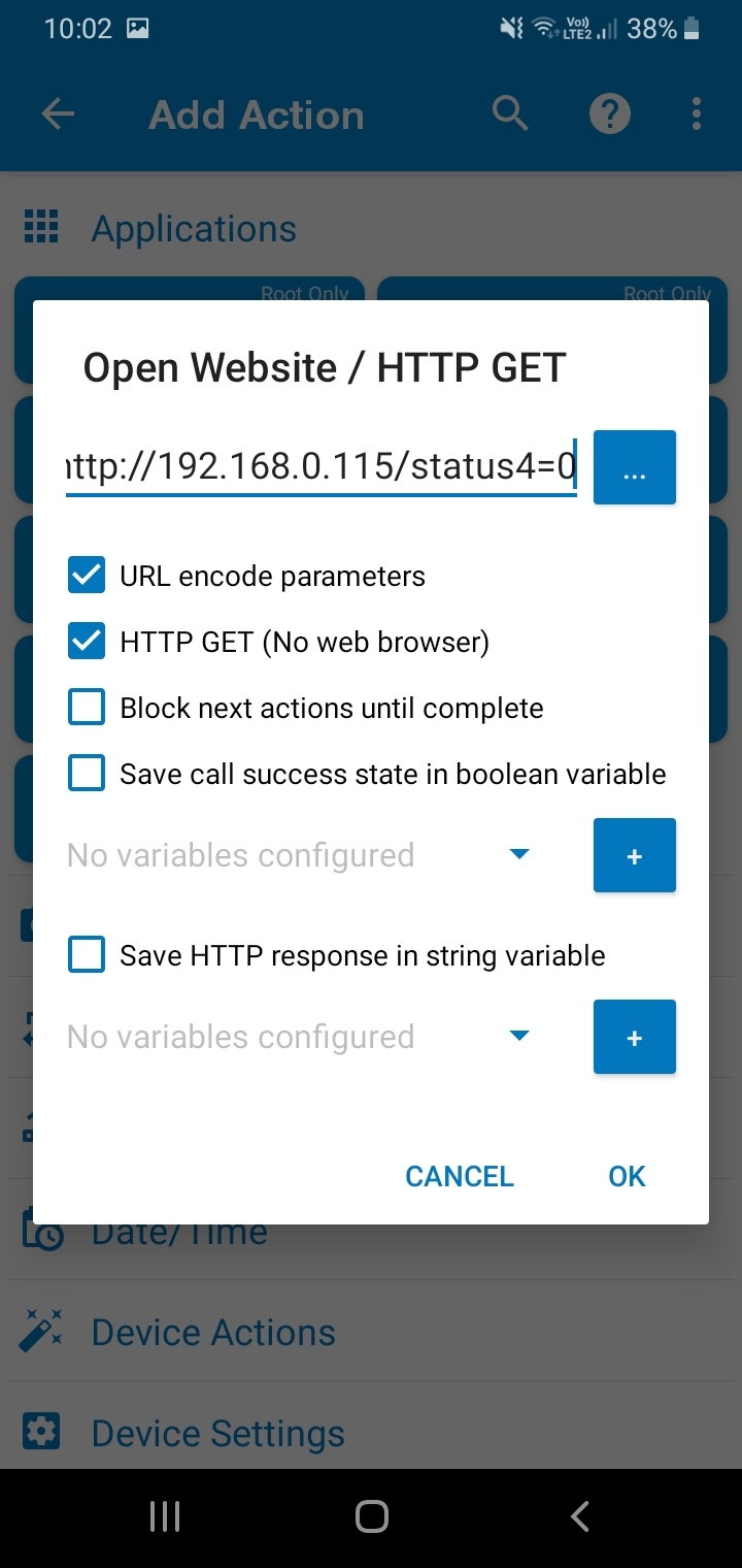
Tick Url Encode Parameters, HTTP Get(No Web Browser) , Save Call Success State and Press Ok
Enter Full Charge on Top and Save
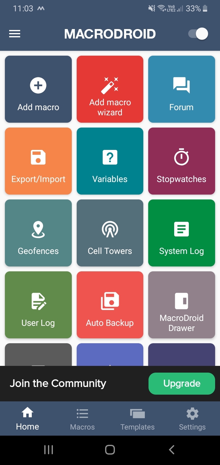
Finally Enable Slide Bar to Top Right .
Testing With Mobile.
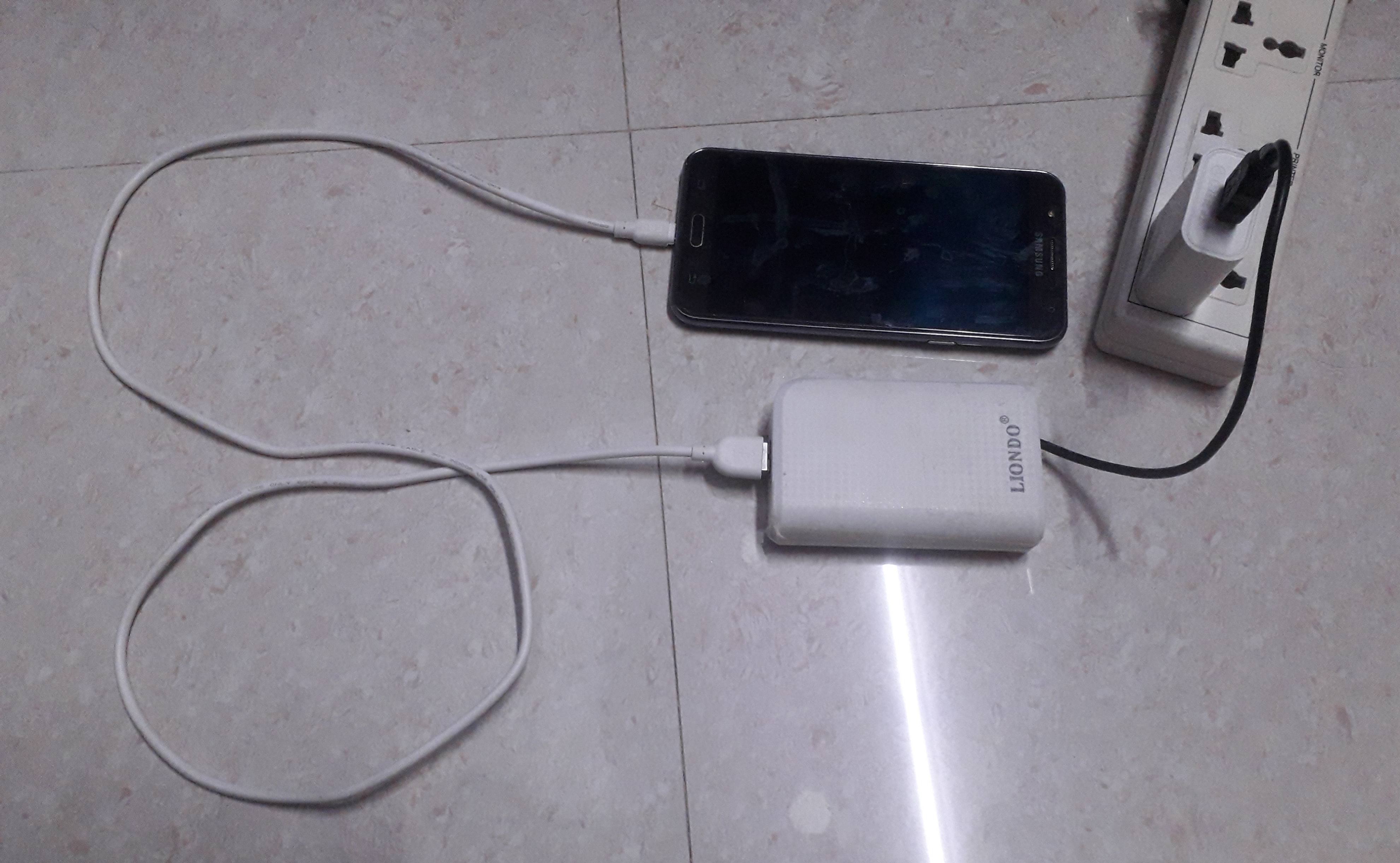
Connet USB male to wall socket,charger wire of your mobile to usb female. power ON charger, led will be ON and switches off automatically after full charge and supply cuts off to Mobile. .
Note: Every time kept mobile in charging do not forget to enable Macrodroid app and switch on WIFi on mobile.