Miniature Lock Box Puzzle - 3D Printed
by CrazyBlackStone in Workshop > 3D Printing
7554 Views, 57 Favorites, 0 Comments
Miniature Lock Box Puzzle - 3D Printed
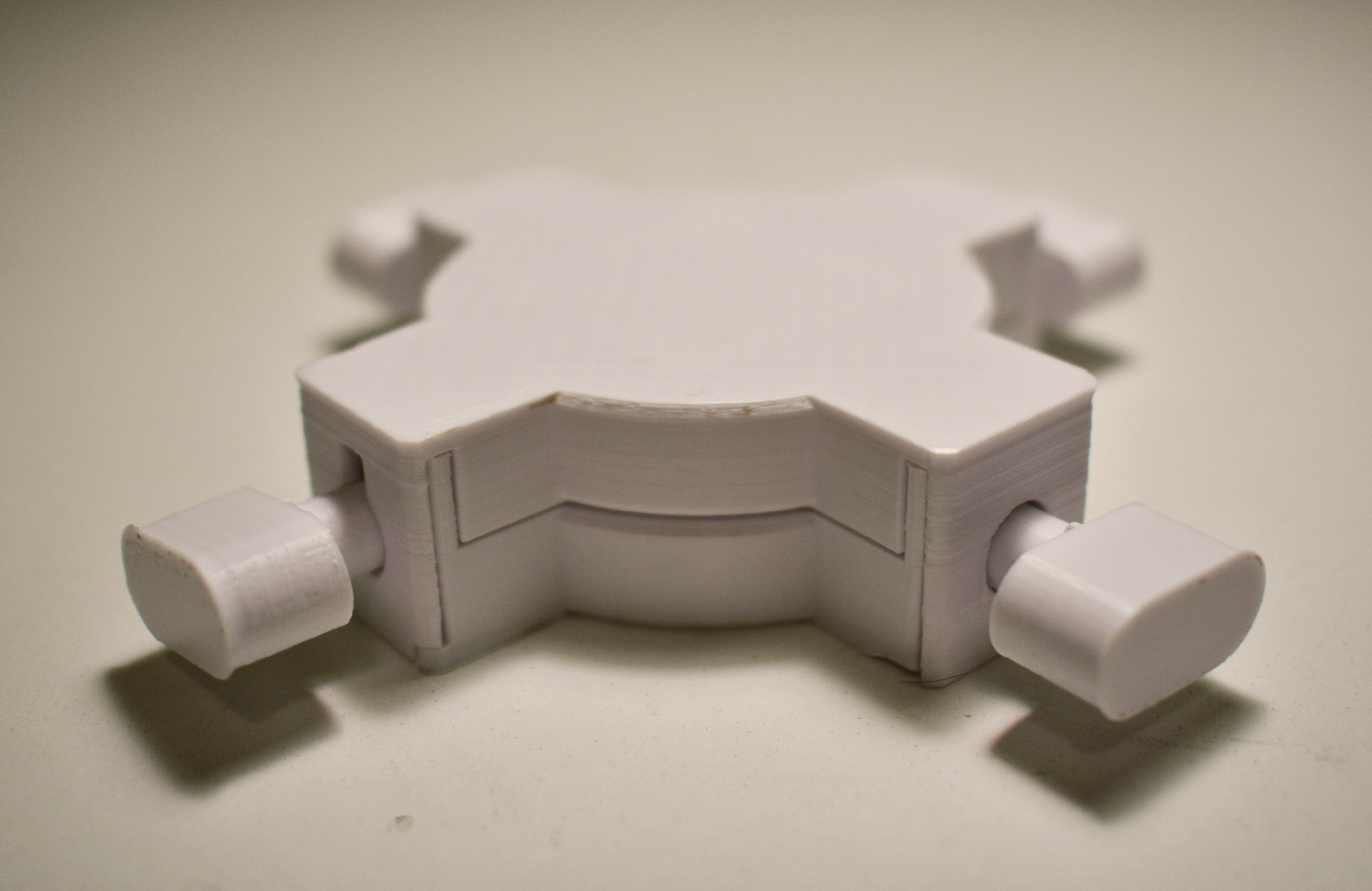
Hi, my name is Xieshi, and this is a miniature lock box puzzle with four locks (or whatever you want to call it, I ran out of names to call this thing). Also published on Thingiverse.
What is this puzzle?
This is an original puzzle with no universal name, so I just decided to call it a mini lock box puzzle. It is a small box with four key holes on the outside. If a key is inserted into any one of the key holes, the box is unable to be opened. Therefore, all four keys must be removed for the content inside to be revealed.
How does it work?
The keys and their respective holes are structured similar to a circular maze. You must rotate and push/pull on the key in order to find an exit to the maze. And similar to a maze, there are dead ends, so based on luck, you can get really lucky on the first try, or you can be stuck on one key for over 20 minutes. Since there are four key holes with different mazes, you have four chances to test your luck and skill.
What makes it good?
This puzzle has the advantage of being able to be replayed many times. The keys can be inserted back in easily by pushing and blindly rotating the key as it goes in. And because of the amount of key holes and the material being opaque, it's extremely likely that the next time you play it, you won't remember a single thing on what the solution is.
Supplies
This puzzle is completely 3D printable without supports. So you will only need:
- Well-tuned 3D printer*
- Opaque filament
As for print settings, I recommend the following:
- Layer height: ≤0.12mm
- Nozzle diameter: ≤0.4mm
*As long as your printer isn't equivalent to a knockoff of potato, everything should be okay
As you can probably tell, this puzzle is designed in Fusion 360. So if you want to make your own version of this puzzle, make sure you have Fusion 360 installed.
Design Process - Body - Base Sketch and Extrude
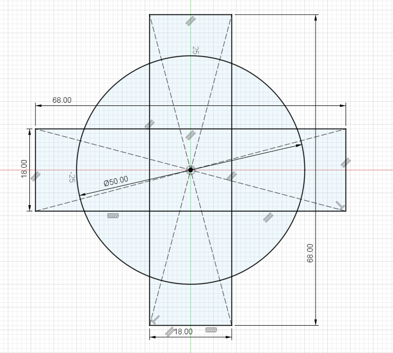
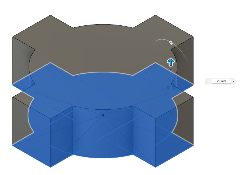
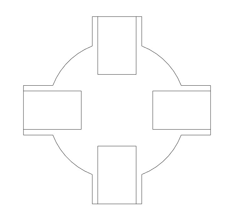
Start by creating a sketch on the XY plane. Follow the sketch and its dimensions shown in the picture. There should be two center point rectangles and one circle.
Then extrude the base sketch by 20mm.
You may use the "trim" tool found under create to make this and some other sketches look cleaner. However, I would rather not trim the sketches as you might need to adjust the dimensions later.
Design Process - Body - Key Hole Sketch
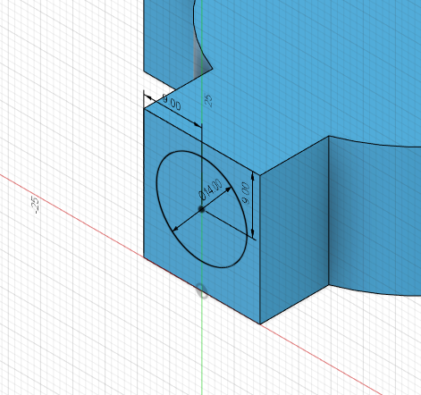
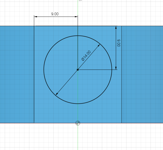
Create a sketch on one of the sides where the key hole will go.
Draw a 14mm diameter circle and then dimension it like shown in the picture. The circle is intentionally not centered vertically as we will need the space below it later on.
Design Process - Body - Extrude Key Holes
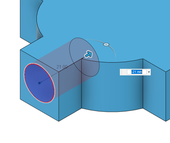
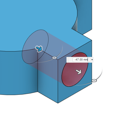
Extrude the key holes into the part by 21mm. Make sure the cut operation is selected.
Then navigate to the left side of the screen and click on the arrow next to "sketches" to collapse all sketches. Right click on the latest sketch and click "show/hide" to allow the sketch to be extruded again.
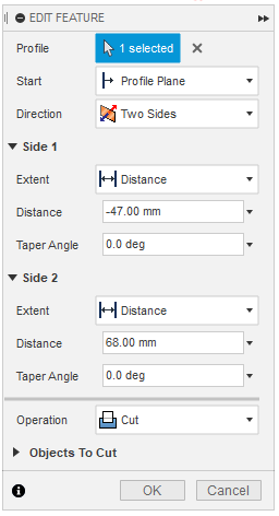
This time, extrude the same sketch with the "two sides" option selected for direction. Have side 1 extrude -49mm and side 2 extrude 68mm. This should create a 21mm deep hole on the other side.
Design Process - Body - Repeat Key Holes
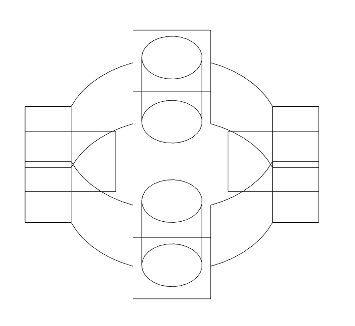
Repeat step 2-3 for the other two sides. First drawing the sketch then extruding two times.
The end result should be four equally deep holes on all four sides like shown in the wireframe picture.
Design Process - Body - Offset Plane
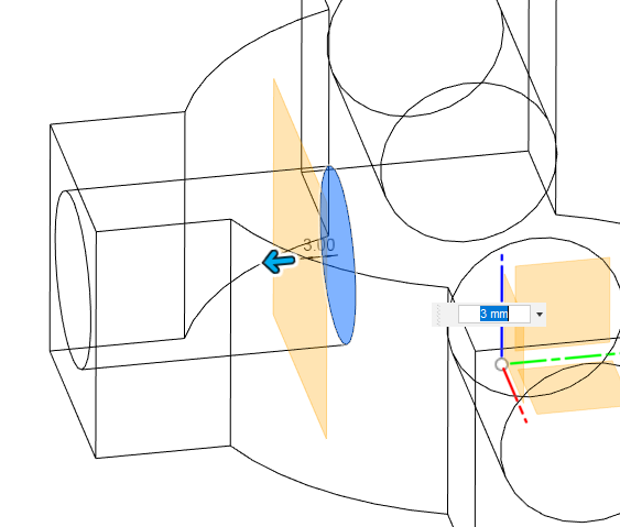
Construct an offset plane 3mm from the base of the key hole like shown in the picture.
Then create a sketch on that offset plane.
Design Process - Body - Sketch - Project
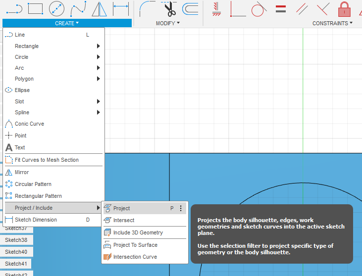
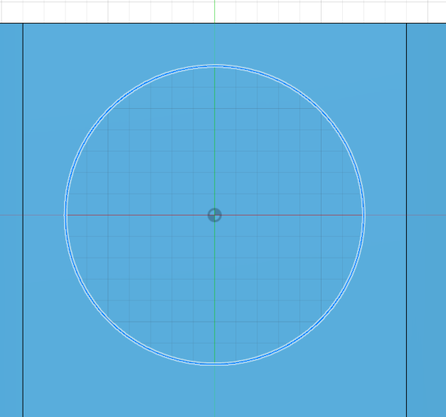
On the sketch, use the project tool found under Create - Project/Include. Select the outer rim of the key hole and click "OK".
This should project the outline of the key hole onto the sketch.
Design Process - Body - Sketch - Center Circle
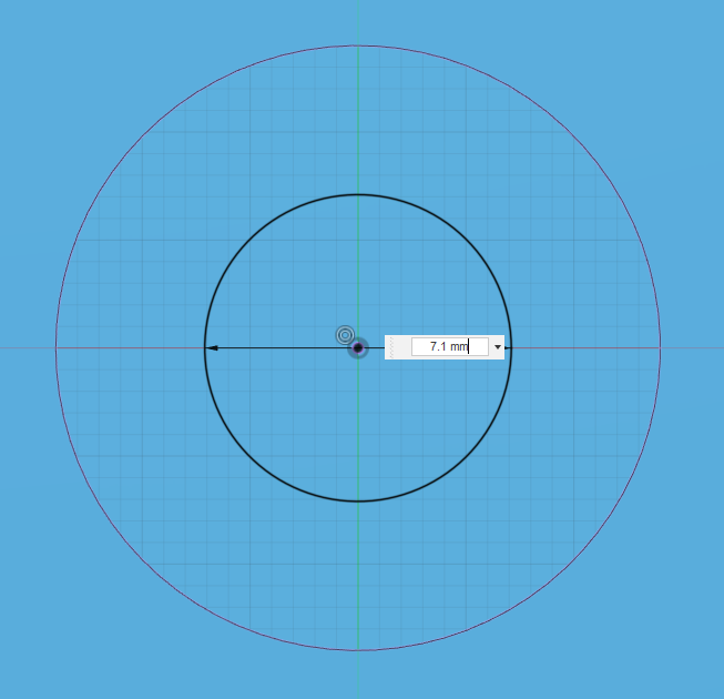
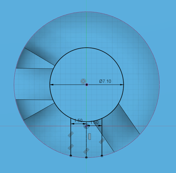
Create a 7.1mm diameter circle in the center of the key hole that you just projected.
The diameter of the circle may depend on your printer and slicer. Consider changing the diameter to 7.3mm if your printer or slicer is bad at clearance.
Design Process - Body - Sketch - Construction Line
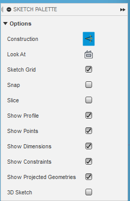
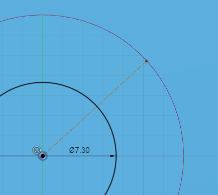
Turn on construction in the sketch palette. Then draw a line from the center to the edge of the key hole. Placement of the line doesn't matter as it is meant to be random as you will see later on.
Design Process - Body - Sketch - Cutout Lines
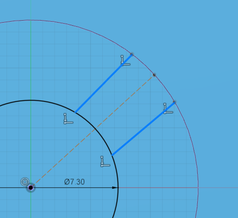
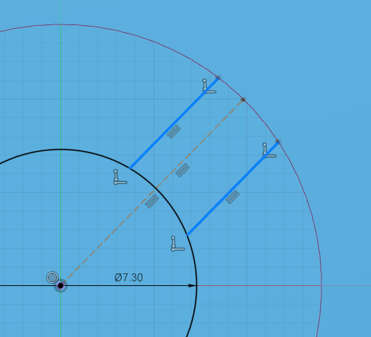
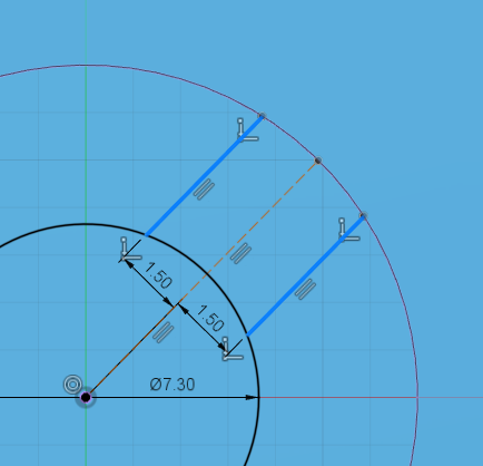
Turn off construction. Then draw two lines that are coincident with the inner circle and the projected key hole, one on each side of the construction line. These are the cutouts for the key to pass through.
Use the parallel constraint found in the "constraints" section to make all three lines parallel to each other.
Finally, dimension the line spacing to 1.5mm on each side like shown.
Design Process - Body - Repeat Lines
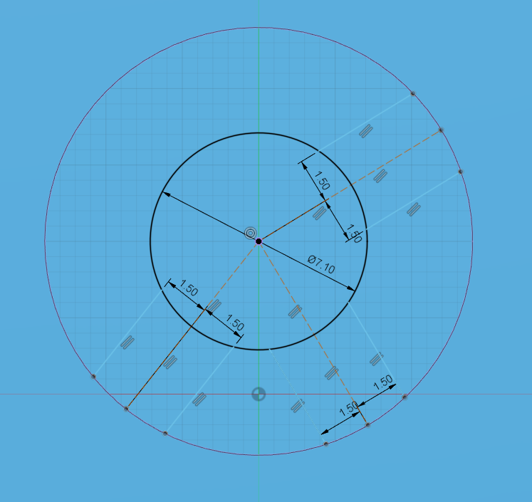
Repeat steps 8 and 9 for 2-4 times. Each time drawing cutouts at different places.
Think of this as a circular maze. Each of the cutouts is a possible path to the next level.
Design Process - Body - Sketch - Extrude "Level Separator"
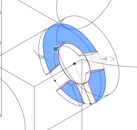
Finish the sketch and extrude it by 1mm. Exclude the cutouts from the extrusion and make sure the join operation is selected.
I call this the "level separator" because it separates each of the levels from each other.
Design Process - Body - Repeat Offset Plane, Sketch, and Extrude
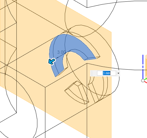
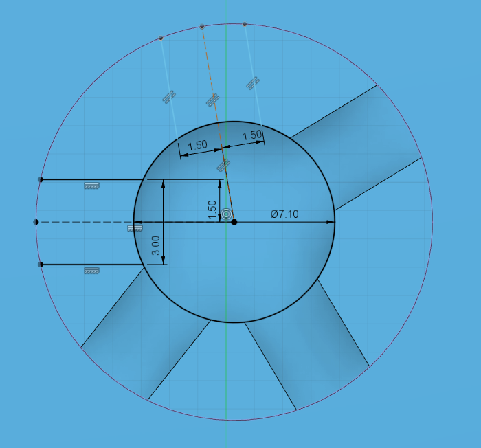
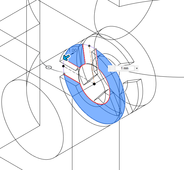
Create a 3mm offset plane on any of the faces created by the previous extrude.
Create a sketch on that offset plane and repeat 6-10 to draw the cutout lines.
Repeat step 11 to extrude the level separator.
Design Process - Body - Dead-ends
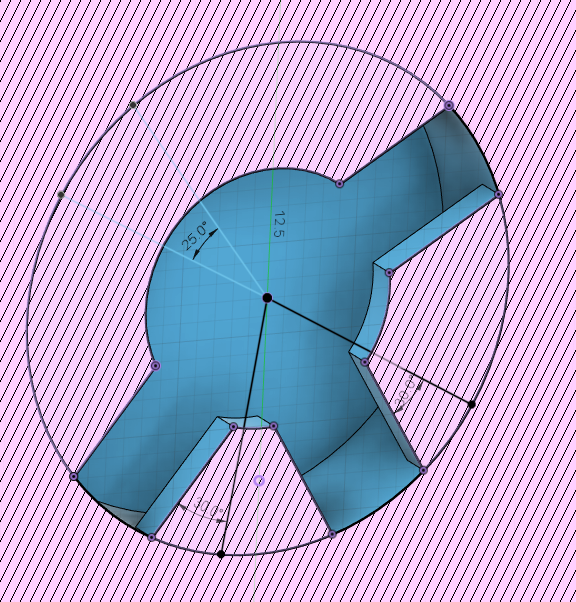
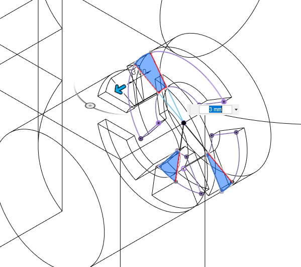
This step is optional.
Create a sketch on the face that is one "level" below the level separator you just made. Then use the "Include 3D Geometry" operation found under "Create - Project/Include" to include the other faces on the same sketch plane.
You may turn on the "Slice" option in the sketch palette to make things easier to work with.
Draw lines from the center like shown in the picture to make dead-ends in the maze. Always make sure there is at least one viable exit or otherwise the player will get stuck forever on that level.
Design Process - Body - Repeat, Repeat, Repeat
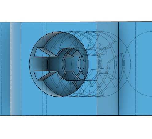
Repeat steps 12-13 for each level until you're one level away from reaching the entrance of the key hole.
Design Process - Body - Key Hole Entrance/Exit
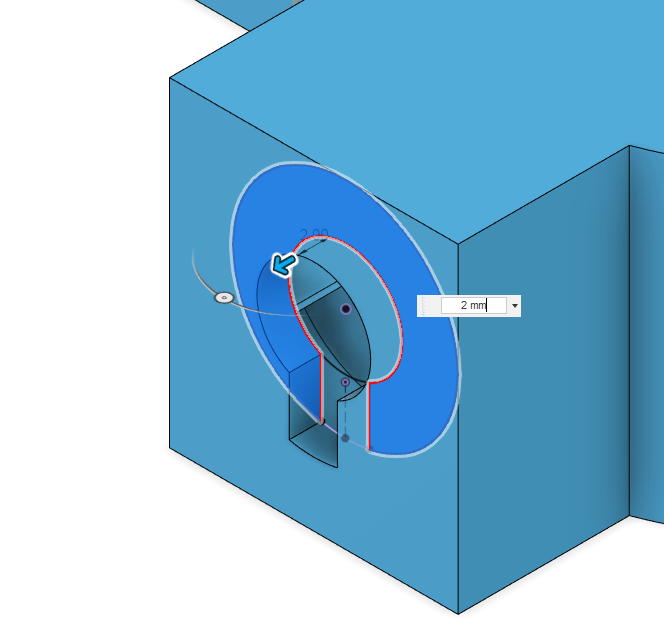
Follow the sketch like shown and make only one cutout, which will be the entrance/exit of that key hole. Make sure there is at least one path the player can take to reach that exit.
Extrude the sketch by 2mm and that should automatically combine with the outer surface. If it is not the case, you may have to look over the previous steps to correct any mistakes.
Design Process - Body - Even More Repeats
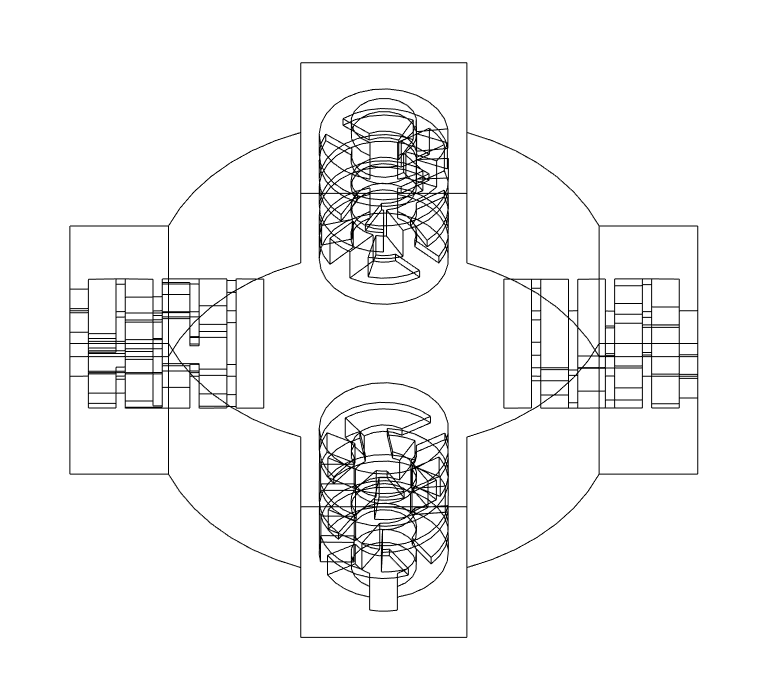
Repeat steps 5-15 on the other three key holes. This is going to take a while.
Once you're done, give yourself a pat on the back because the hardest part is over. If you turn on wireframe view, you should see something similar to this picture.
Design Process - Body - Outer Offset Planes
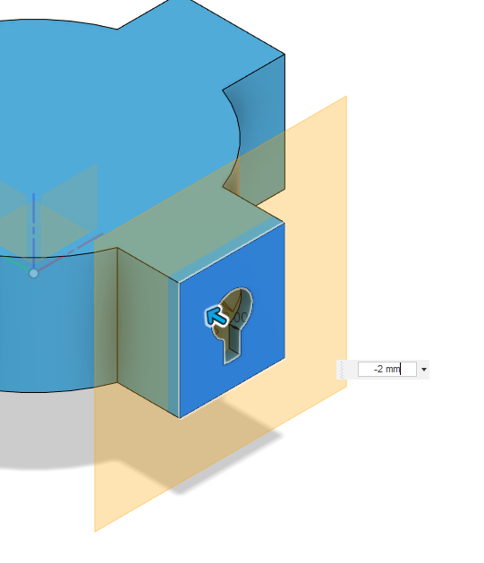
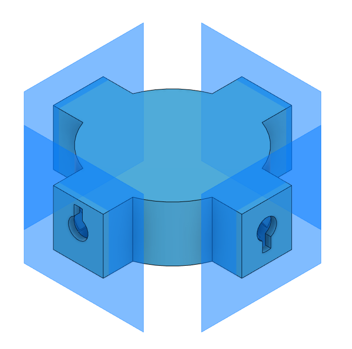
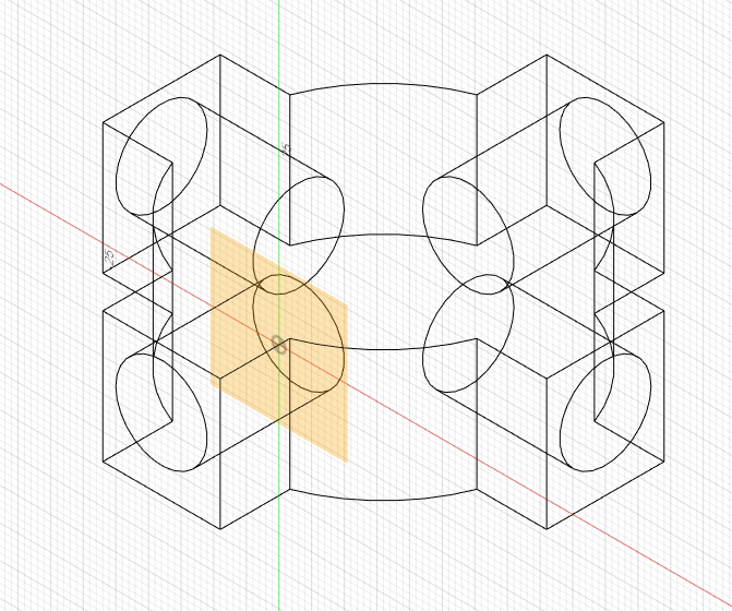
Construct -2mm offset planes from the outer faces of the body. Do so for all four sides.
There should now be four visible offset planes like shown in the second picture.
Design Process - Body - Split Body
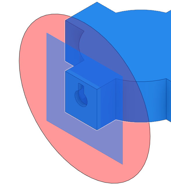
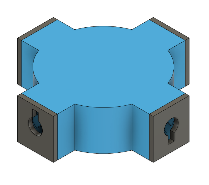
Perform a "split body" operation from the "modify" dropdown. Select big blue body as the body to split and one of the offset planes as the splitting tool. Click "OK" to confirm.
Then Repeat the same process for all four sides.
There should now be five bodies, being the center part and four outer pieces.
Design Process - Body - Vertical Midplane and Split
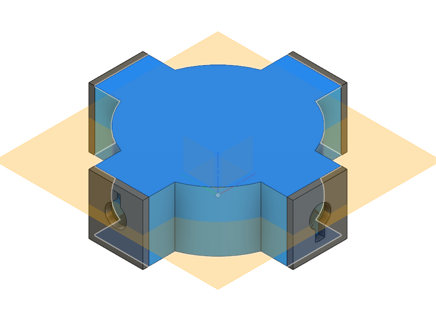
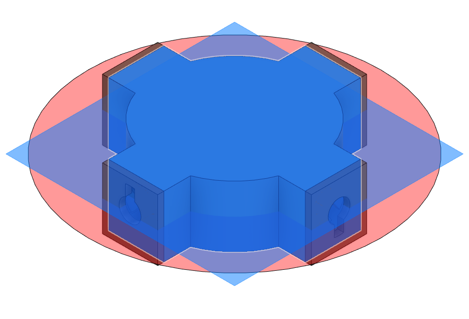
Construct a midplane between the top and bottom faces of the body.
Then use the split body tool to split the main body into top and bottom parts. Make sure to not split the outer parts.
There should now be 6 bodies in total, being the main upper part, main lower part, and four outer pieces.
Design Process - Body - Combine
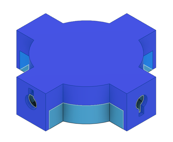
Now combine the upper part of the body with the outer four pieces using the combine tool found under "modify".
There should now only be two bodies. One is the upper part and one is the lower part.
Design Process - Middle Box Cutout
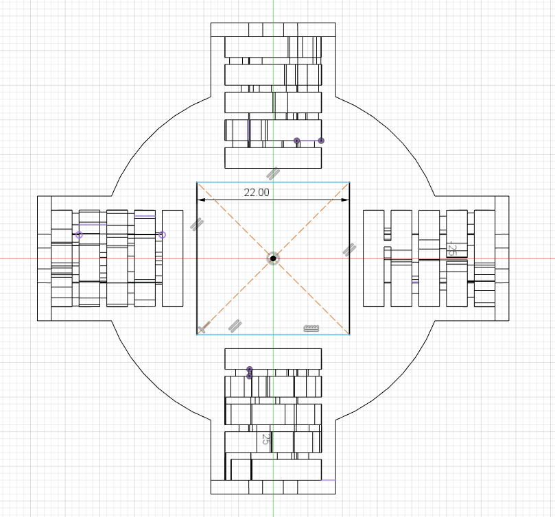
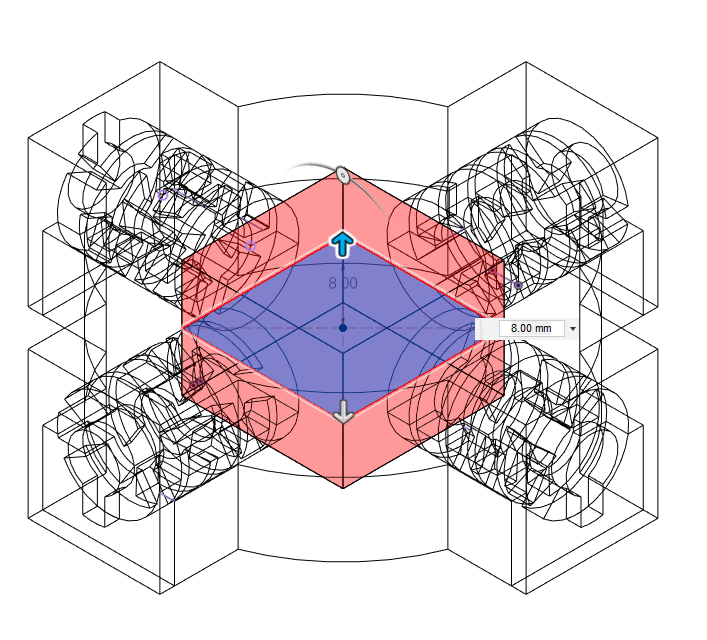
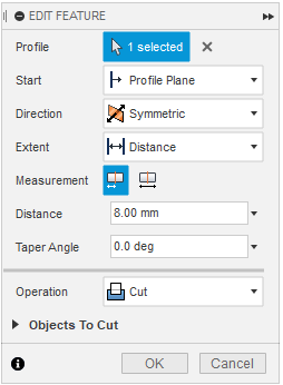
Hide the top part if you need to. Create a sketch on the top of the bottom part and create a 22mm long/wide center point rectangle in the middle of the sketch.
Finish the sketch and extrude 8mm with the "symmetric" direction selected. Make sure the operation is on "cut".
Design Process - Offset the Bottom Faces
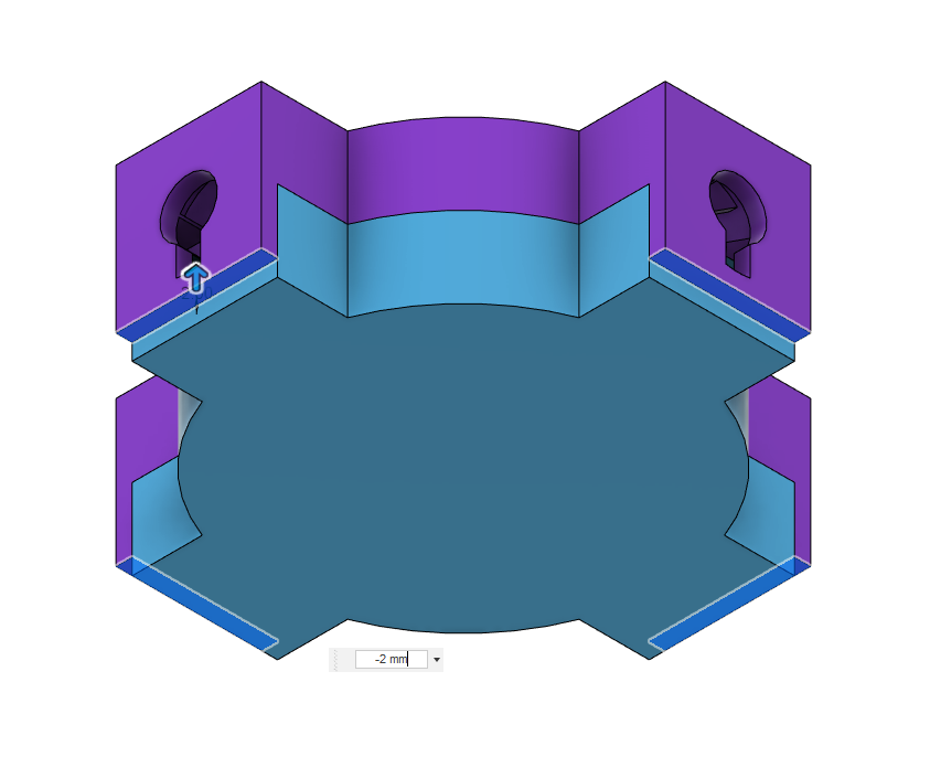
Select the push/pull tool under "modify" and click on all four bottom faces of the upper part. Enter a -2mm offset and click "OK".
Design Process - Body - Extend the Bottom Piece (Sketch)
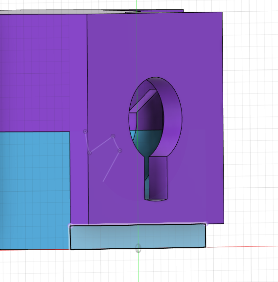
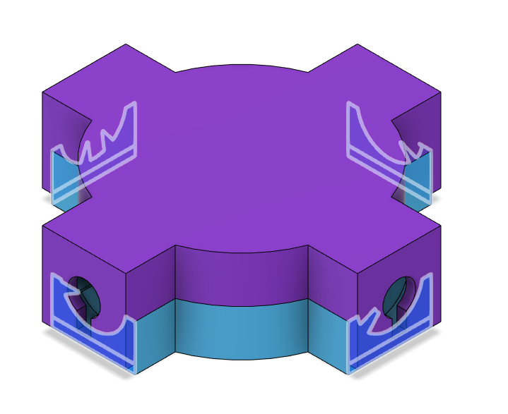
Create a sketch on one of the outer faces of the bottom part. Then use the "project" tool to project the outline of the bottom of the top part onto the sketch.
Do so for all four sides.
Design Process - Body - Extend the Bottom Piece (Extrude)
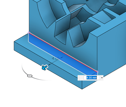
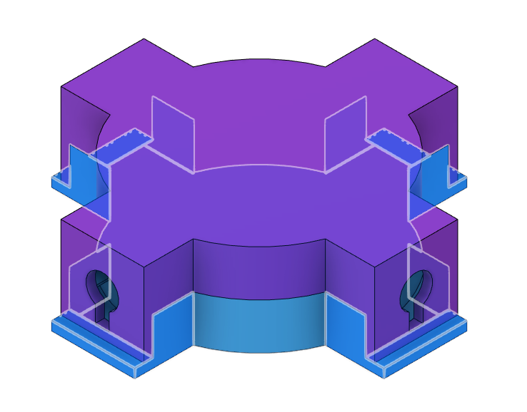
Extrude the sketches you just made out by 4mm like shown in the picture.
You may need to hide the top part in order to not combine the two separate parts back together.
Design Process - Body - Identifier Marks (Optional)
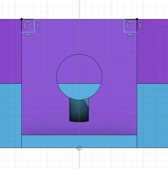
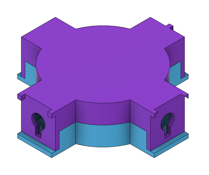
This step is optional. Create a sketch on one of the outer faces of the top part and create identifier marks/cutouts similar to how it's shown in the picture. It's up to you how many sides you do this on.
Next, extrude those identifier marks by 2mm.
Keep in mind that without identifier marks, you likely won't be able to tell which side is meant to match which.
Design Process - Body - Extend the Outer Faces of the Bottom Piece
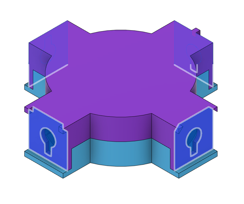
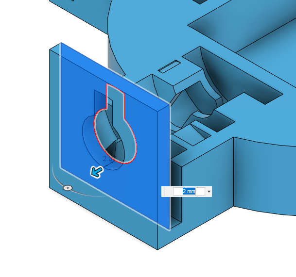
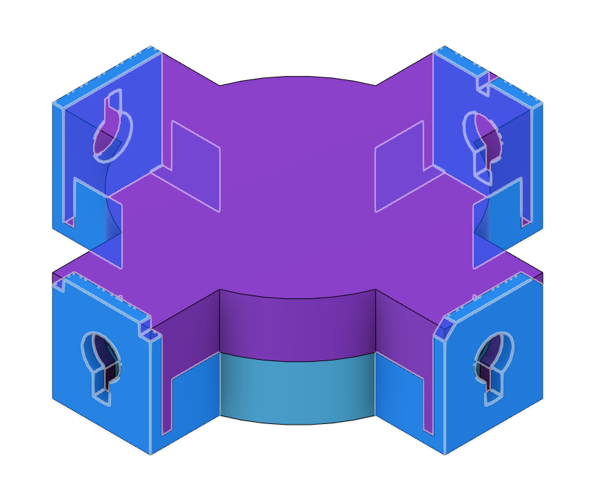
Create blank sketches on the outer faces of the top part. The empty sketches act like a projection of the face.
Next, hide the top part and extrude the sketches outwards by 2mm. Make sure the extrusions join the bottom part but does not combine with the top.
Design Process - Body - Add Tolerance and Clearance
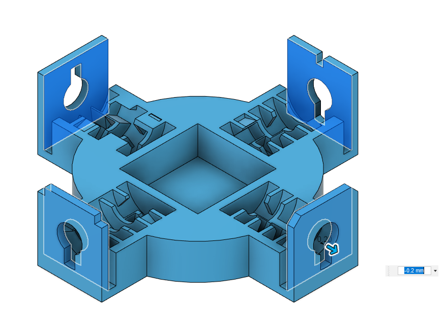
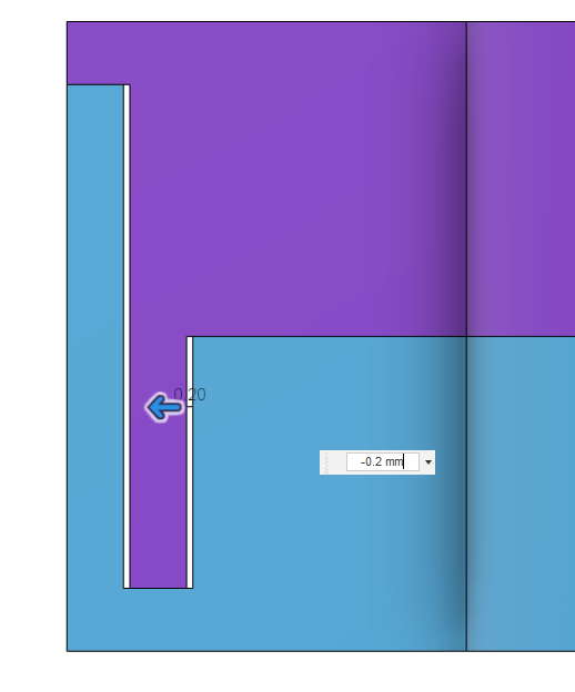
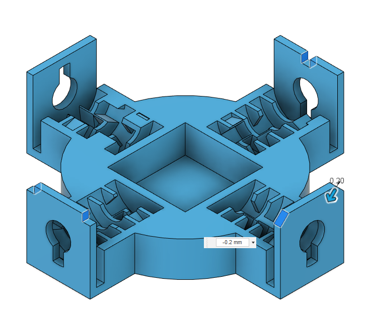
Use the push/pull tool from the "modify" menu and select certain touching faces to offset them and give them clearance. I chose 0.2mm because it fits my printer well.
Unless your 3D printer is perfect, you will need to add clearance to the parts or otherwise they may not fit or may fit too tightly.
Design Process - Body - Chamfers and Done!
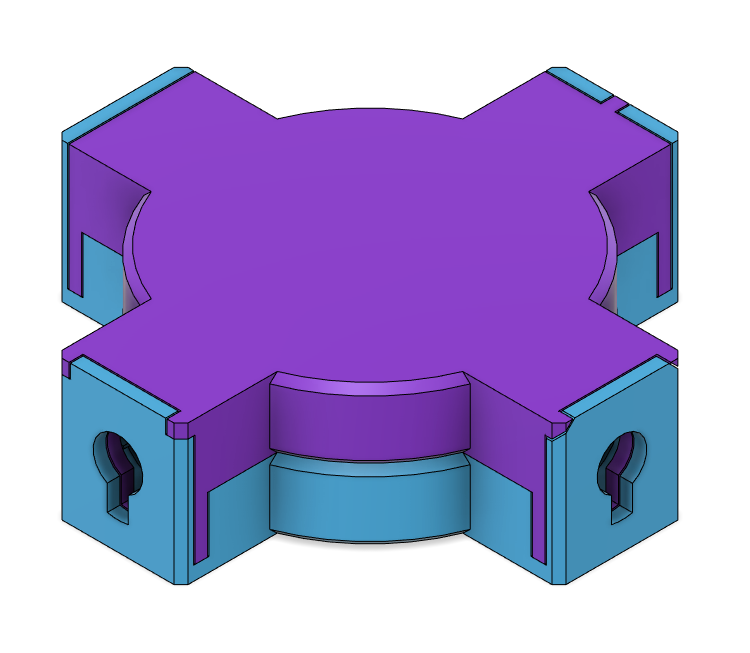
Add a few chamfers here and there to make the thing look better and easier to open.
And that's the puzzle body done!
Design Process - Key - Base
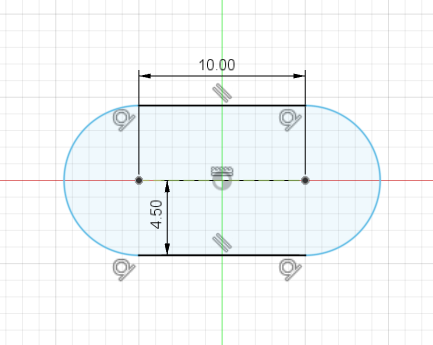
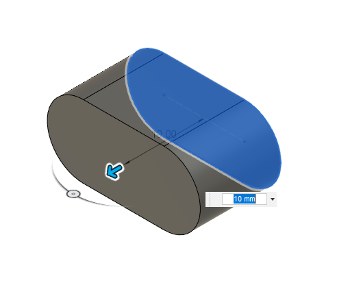
This is the key, and it is used for locking/unlocking the puzzle.
Create a sketch on the XY plane. Then draw a slot with 4.5mm radius and 10mm length in the middle of the sketch, like shown in the picture.
Finally extrude the base sketch by 10mm.
Design Process - Key - Main Cylinder
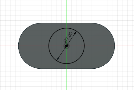
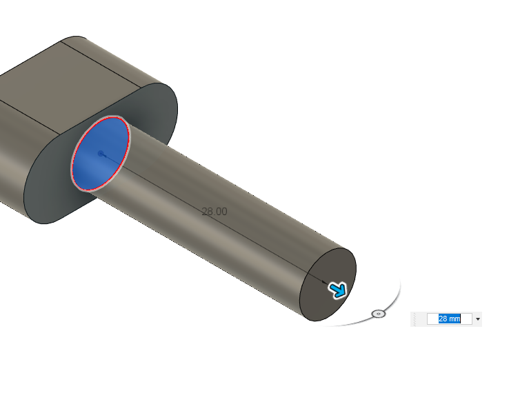
Create a sketch on the top/bottom face of the base. Then create a 7mm diameter circle in the middle of the sketch.
Extrude it by 28mm.
Design Process - Key - Key Slot
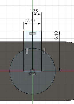
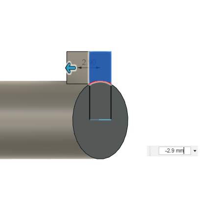
Create a sketch on top of the cylinder.
Afterwards, create a 2.7mmx6.1mm rectangle with the dimensions like shown in the picture. Make sure it is centered with the cylinder
Extrude the outer part of the sketch by 2.9mm.
Design Process - Key - Chamfer
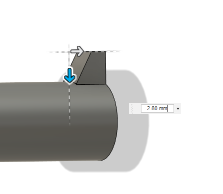
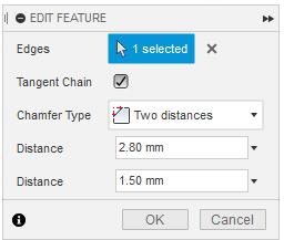
Add a chamfer (under "modify" menu) with "two distances" selected for chamfer type. The two distances are 2.8mm horizontally and 1.5mm vertically.
Design Process - Key - Done!
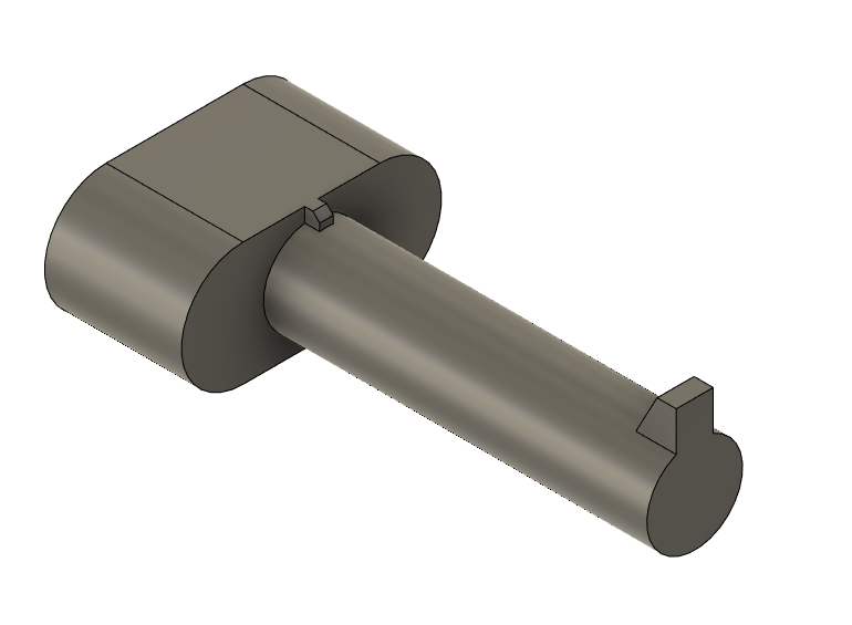
That's the key done!
I added a little thing on top of the base to show where the key slot is, but that's purely optional.
Design Process - Assembly
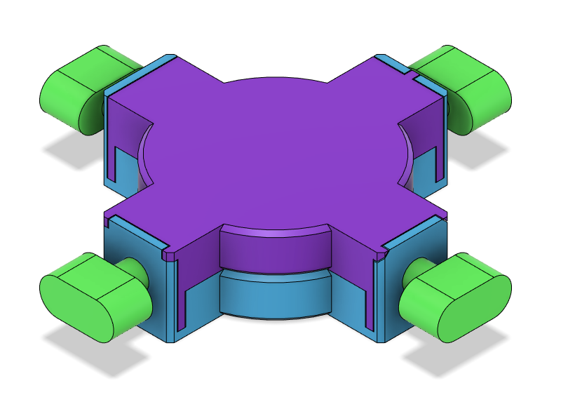
This is what the part looks like in an assembly. I will also attach a step file for the assembly and f3d files for the puzzle in case anyone wants to edit my work.
Physical Assembly - 3D Print
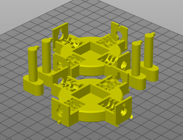
Export as STL and print both of the body pieces and four keys (attached). Orient them like shown in the picture.
Use 0.12mm or lower layer height with a 0.4mm or smaller nozzle.
It seems that some people are having issues with the key shaft being too large. So I made a version of the key with a 6.8mm diameter shaft instead of 7mm. This should give more clearance but may turn out a little loose for certain printers.
Physical Assembly - Video Animation
This video animation and the following steps shows how to assemble this puzzle. It's really not very hard.
Physical Assembly - Main Body
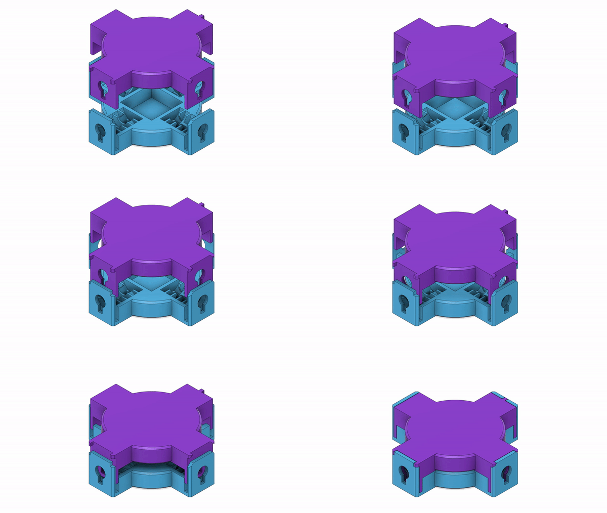.gif)
Align the top part's identifier markings with that of the bottom part and locate the slots on the bottom part where the top part will fit into.
After aligning, slide the top part onto the bottom part. The two parts should click together nicely.
If you are unable to play the GIF, refer to the video animation.
Physical Assembly - Keys
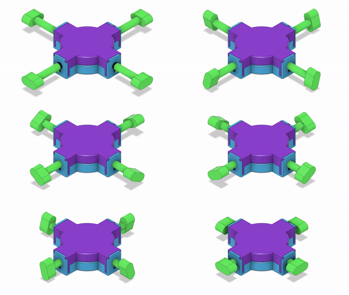
Insert all four keys into their holes. Actively push in the keys and turn them in all directions so that they can go down the levels.
Make sure the keys are in all the way.
If you are unable to play the GIF, refer to the video animation.
How to Play
This is a video of me solving the puzzle. Sorry for the bad focus. :(
To play this puzzle, you will first need all four keys to be inserted into the box, and your objective is to open the box by removing the keys.
The strategy
To start, choose a key you want to work on and turn it in all directions constantly while actively pulling on the key. There will be a clear feedback when the key passes through a level. Keep doing this until you get the key out or find yourself in a dead-end.
If you find yourself in a dead-end, push the key back (into the box) by one level and try to find a different exit on that level. If there are no viable exits, push it back one more level and do the same.
If you find yourself continuing to end up in the same dead-end, memorize what paths you took and try to look for different paths in each of the levels. Take it slow and make sure look for exits and move down one level at a time.
A big part of this game is luck and guessing. So as long as you have the simple strategies mastered, you're good to go.
Time
The time to remove the lock depends on your luck. It can take down to 5 seconds or up to 10 minutes to remove one key. It takes around 1-3 minutes on average to remove one key for beginners.
Content in the box
The box has enough room in the middle for a folded piece of paper. The content on that paper is up to you. All four keys need to be removed before content inside is able to be revealed.
Conclusion
I hope that you try this puzzle out and print it. It's great for treasure hunts with kids or to simply entertain yourself when you're bored. You can even grab a few friends and try to speed solve it!
Thank you for reading this and have a great day!