Mini Plotter V1


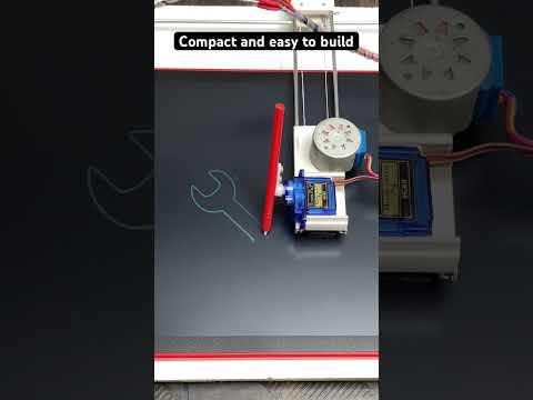
In this project, I'd like to share how to build a Mini cnc writing machine (Paperless). The project is based on Arduino nano and runs on GRBL code. It consists of two 28byj-48 Stepper motors, one servo motor and 3D printed parts that provide movement in two axes. I used LCD writing pad instead of paper as LCD writing pads are portable electronic devices that can be used for drawing, writing, sketching, etc. This reduces wastage of paper. This machine is made up of easily available parts like Arduino nano, 28byj-48 Stepper motors, servo motor, bicycle’s spokes, bearings, string/thread and 3d printed parts. Let’s make it.
Supplies


- 1pcs x Arduino Nano
- 2pcs x 28byj-48 Stepper motors
- 1pcs x Servo Motor
- 2pcs x ULN2003 Stepper Motor Driver IC
- 4pcs x Bicycle’s spokes
- 2pcs x Header pins
- 1pcs x PCB Sheet (10cm X 2.5cm)
- 1pcs x Plywood sheet (40cm X 30cm)
- 1pcs x String / Thread
- 1pcs x Power Supply 9V DC.
- 1pcs x Female DC Power jack
- 2pcs x Old gas cylinder washers
- 1pcs x LCD writing pad
- 2pcs x Idler Bearing
- 2pcs x Jumper Wires
- Electrical wire Casing/duct
- 3D printed parts
- Some Screws
- Super glue
Tools used
- 3D printer
- Mini drill machine
- Screw driver set
- Soldering iron
- Vernier Caliper Digital
- Measuring tape/ scale
X-axis and Y-axis


I have used bicycle spokes as the rail guides for this CNC machine. The idea of using bicycle spokes as linear rails make the whole machine affordable and of less weight.
Total casing/duct parts required:
For X-axis and Y-axis stepper motor = 50 mm
For X-axis and Y-axis pulley = 20 mm
For Servo Motor support = 24 mm
Linear rail dimensions:
Four bicycle’s spokes are used as linear rail. The length of each spoke is 300 mm.
This mini CNC machine general part includes two 28BYJ-48 stepper motors controlled by Arduino Nano with the help of two ULN2003 stepper motor drivers. The X-axis and Y-axis of the plotter are made up of electrical wire casing/duct and bicycle’s spokes. Y-axis slider moves linearly moves linearly up and down between the 3D printed stands and X-axis slider forward and backward which carries Servo motor whose arm attached with a pen.
Base Plate


Take a Plywood sheet and cut a piece of size 40cm X 30cm.
X-axis and Y-axis consists of an electric duct/casing pieces on which stepper motors are attached.
For the pulley of the stepper motor I have used an old gas cylinder washer attached to a 3D printed pulley. This washer helps in gripping the string.
Make necessary holes on the electric duct casing to hold stepper motor
Also cut a small part of duct/casing to hold idler pulley as per the dimensions shown in images.
Similar steps to be followed to built Y-axis.
Attach the pulleys on each stepper motor and tied up the string/thread between the motor pulley and the idler pulley of both axis.
I have used bicycle spokes as the rail guides for this CNC machine. Cut the bent part of the bicycle spokes.
On one end attach a stepper motor and on other end attach an idler 3d printed pulley mounted on the duct/casing. In this way X and Y axis are ready.
Join these parts with the help of superglue.
The X-axis is attached perpendicularly to the Y-axis guide via 3D printed part as shown in images.
Schematics and Circuit Diagram


The Connection should be made as per the circuit diagram. The motors (28byj-48) are connected to a controller card (Arduino Nano) that uses the chip ULN2003.
This board is connected to pins A0, A1, A2, A3 for the Y-Axis (IN4->IN1)
D2, D3, D4, D5 Digital pins to the X-Axis (IN4->IN1) and
The servomotor connected to pin 11 h.
To overcome the complexity of the circuit connections I have made a custom PCB with header pins, some jumper wires and DC power jack. You can make your own PCB or you can order online.
I have powered this PCB with 9v-12v DC power supply. Arduino Nano is powered with PC.
Software Used
Download Arduino IDE
Download Inkscape version 0.92
https://inkscape.org/release/0.92.2/windows/
Download Universal Gcode Sender
https://winder.github.io/ugs_website/download/
Download GRBL firmware:
Upload GRBL

Download the library file > unzip it and load to arduino as:
File > Example > grbl upload compile and upload code to arduino nano.
If you find any error while uploading the code, see this video:
Create Gcode File Using Inkscape
I used Inkscape software to create Gcode file.
Download all the above mentioned software along with 4xidraw Extension.
Extract and install all the software.
Open Inkscape file location > copy all the files of 4xidraw Extension to the extensions folder of Inkscape.
After adding 4xidraw extension to Inkscape follow these steps to create Gcode file:
Open Inkscape > File tab > Document Properties > set page size as 120mm x 100mm
Drag and drop the particular image of your choice, adjust the image size accordingly and place it on the page.
Select the image > Go to Trace Bitmap > convert to path
Delete the previously inserted image.
Then go to Extensions tab > Click on 4xidraw Tools > Save the parameters as shown in images > Click Apply > Gcode generated.
Assembly of All Parts


With the help of screws all final parts are assembled together to form basic structure of the machine. The 28byj-48 Stepper Motors with pulley belt mechanism is used for both X-axis and Y-axis.
Attach the Y-axis stands on the base plate made up of Plywood sheet with the help of screws. Hold the Y-axis casing inside the cavity provided in the 3D printed stands.
Mount the Z-axis servo motor on the slider of X-axis with the pen attached to the servo motor arm with the help of two screws.
One end of the X-axis is attached to the slider of Y-axis and the other end is supported by a roller bearing mounted on the electrical duct/casing piece.
Tie the hanging wires of X-axis stepper and servo motor using plastic ties or with cable wrap.
After completing all this process, place the LCD writing tab on the plywood such that all the whole area of LCD writing tab is covered.
GRBL Configuration and Calibration
Open GRBL Controller > Select COM port > Set Baud rate 115200 > click on "OPEN"
Go to "COMMANDS" Tab
Enter $$ for GRBL configuration
To calibrate X-axis and Y-axis we need to know current values of $100 and $101 which denote steps per mm for each axis.
To get these values we need to open UGS and connect it with Arduino nano. After successful connection enter $$ in commands tab. Note down the current values of $100 and $101
For Ex:-
Current $100 value = 100
Current $101 value = 150
Enter 10mm to commands to run X-axis and note own the distance travelled by X-axis. In my case
Desired Length = 10mm
Actual Length = 8mm
To Calibrate X-axis use this formula to get the new value of $100 value
New $100 value = (Desired Length / Actual Length)* Current $100 value
(10 / 8) * 100 = 125 = New $100 value
Use similar procedure to calibrate Y-axis.
Enter 10mm to commands to run Y-axis and note own the distance travelled by Y-axis. In my case
Desired Length = 10mm
Actual Length = 8mm
To Calibrate Y-axis use this formula to get the new value of $101 value
New $101 value = (Desired Length / Actual Length )* Current $101 value
(10 / 8) * 150 = 187.5 = New $101 value
Enter this value in command tab:-
$100 = 125
$101 = 187.5
Working


Now it’s time to stream Gcode, open UGS > Go to machine > Reset to zero > go to "FILE MODE" Tab Browse > select your gcode file and hit enter. Your machine starts plotting.
STL Files
Final Words
If you have any query regarding this tutorial, feel free to ask in comments section. Hope you like this project. Thanks for reading my work. I feel glad if you make your own Mini plotter with the help of this tutorial.
Stay tuned to my Instructables channel for more upcoming exciting projects.
Thanks again.