'Mini Mansion' - Visualisation Aid for the Blind
by Wingletang in Workshop > 3D Printing
7263 Views, 49 Favorites, 0 Comments
'Mini Mansion' - Visualisation Aid for the Blind
My wife, Sue, is totally blind.
We have found that 3D printing allows the creation of models that Sue can feel to gain an appreciation of their shape.
To update the old saying, 'One 3D model is worth a thousand words'.
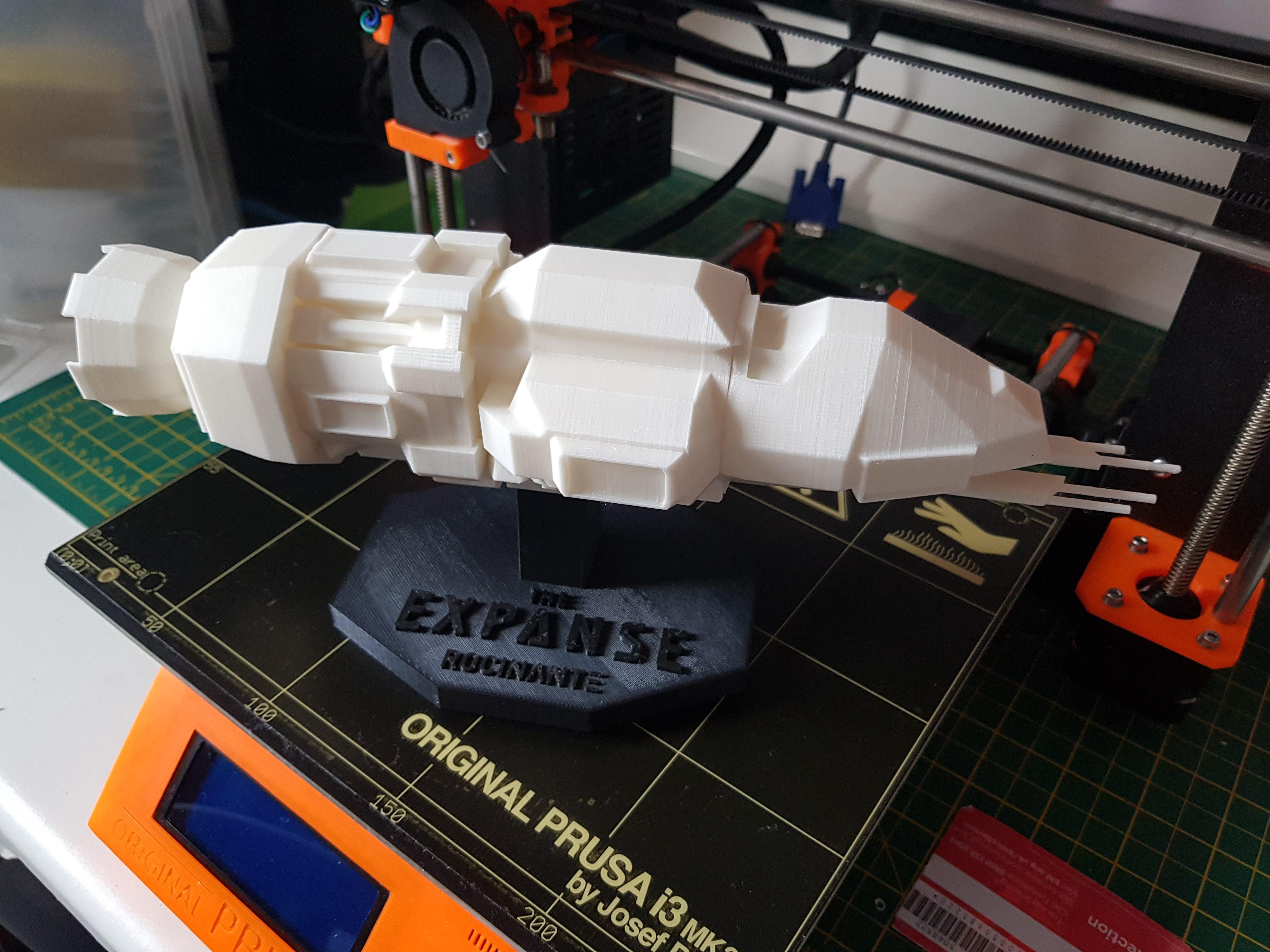
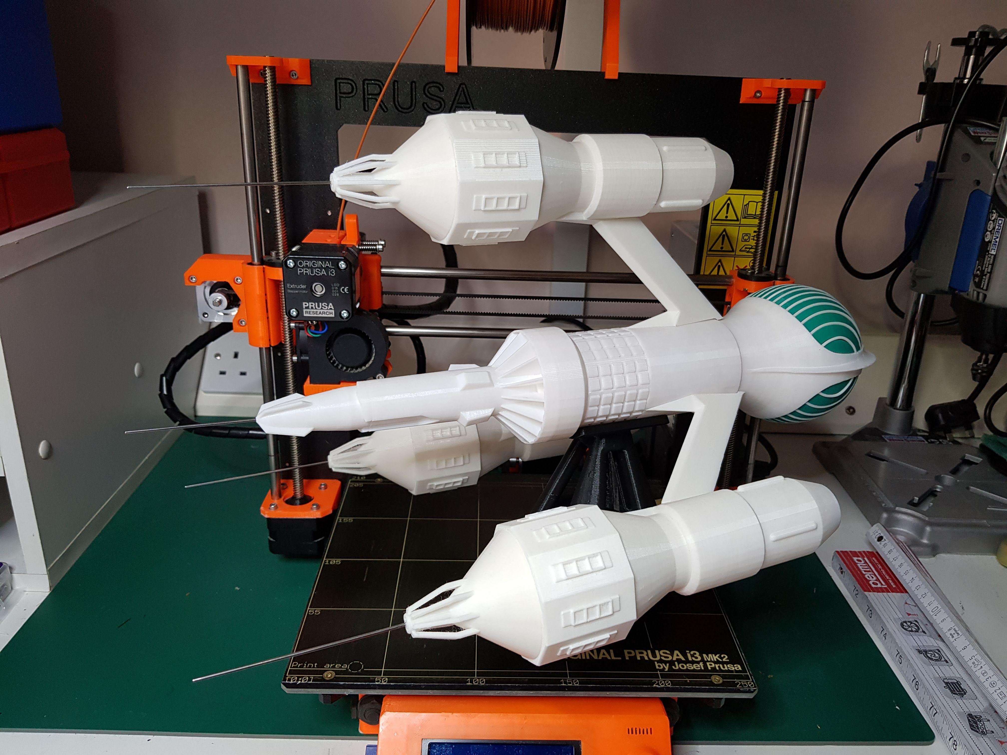
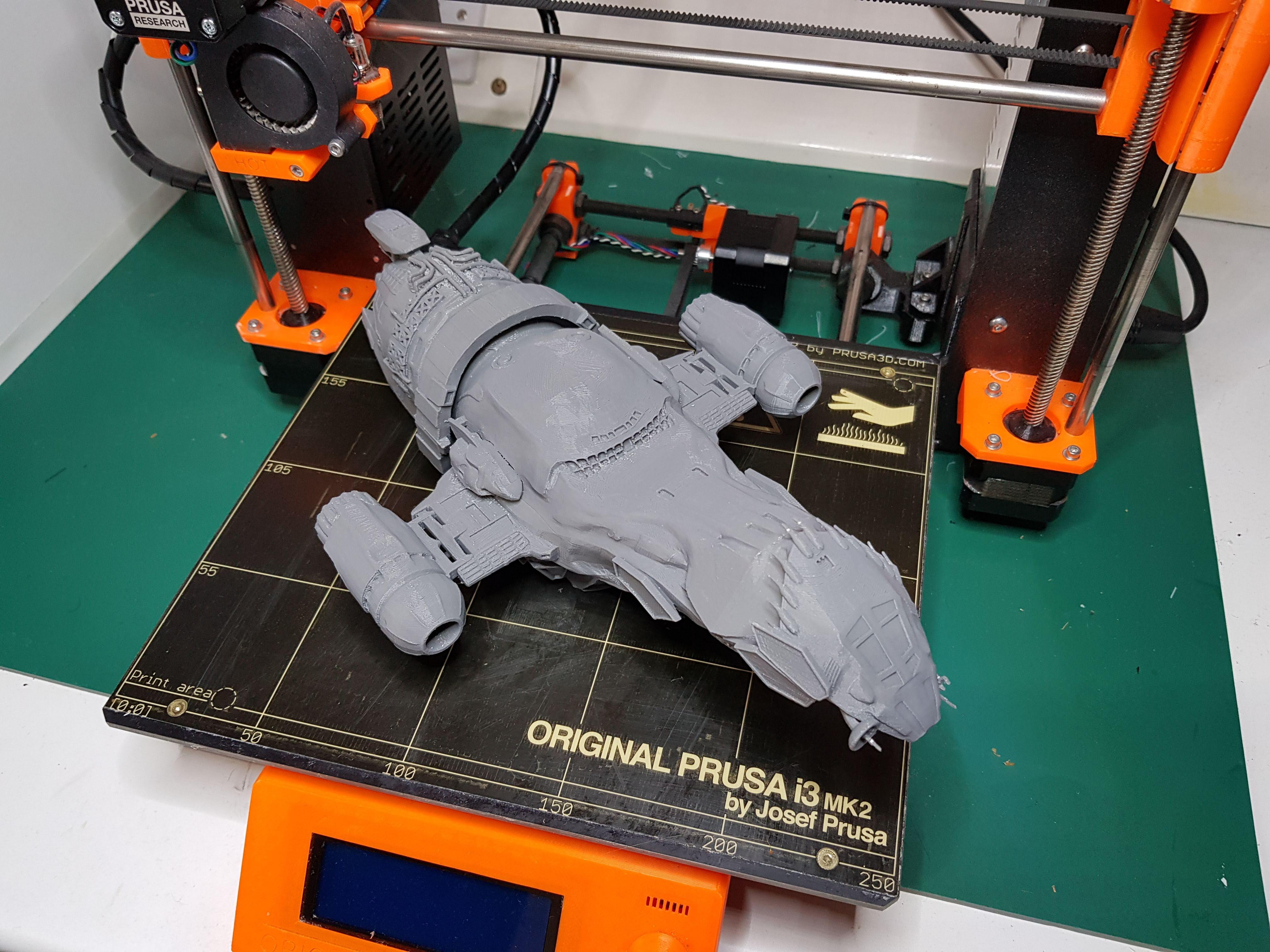
For example, we enjoy science fiction and I have printed 3D models of several spacecraft:
'Rocinante' from the Amazon Prime series 'The Expanse'
'Liberator' from the BBC series 'Blakes 7'.
'Serenity' from the series 'Firefly'.
These ships would be very difficult to describe in words so the models provide excellent visualisation aids for Sue. I printed these models from 3D files downloaded from the internet:
Rocinante: https://www.thingiverse.com/thing:2060060
Liberator: https://www.thingiverse.com/thing:1622169
Serenity: https://www.thingiverse.com/thing:2851469
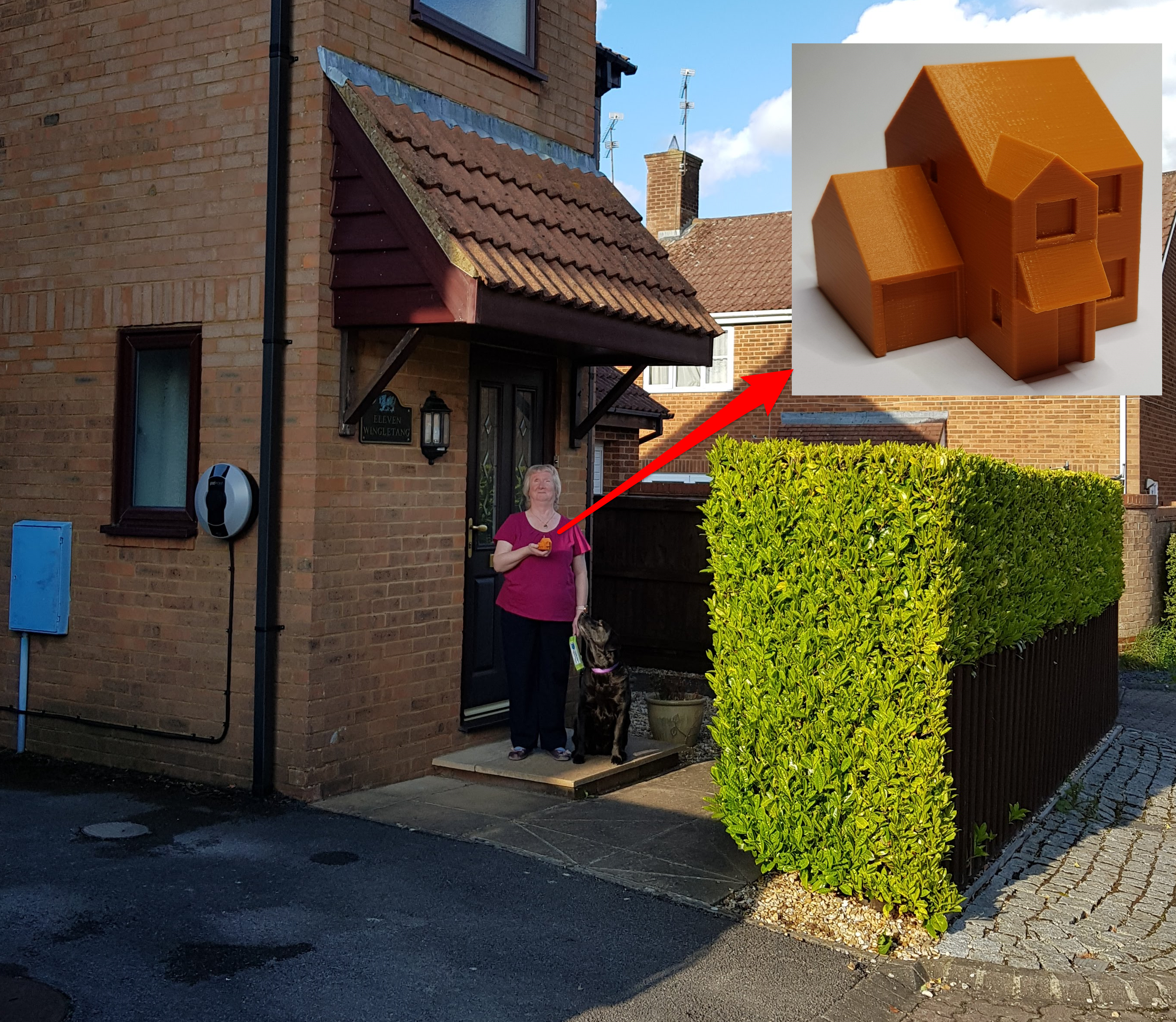
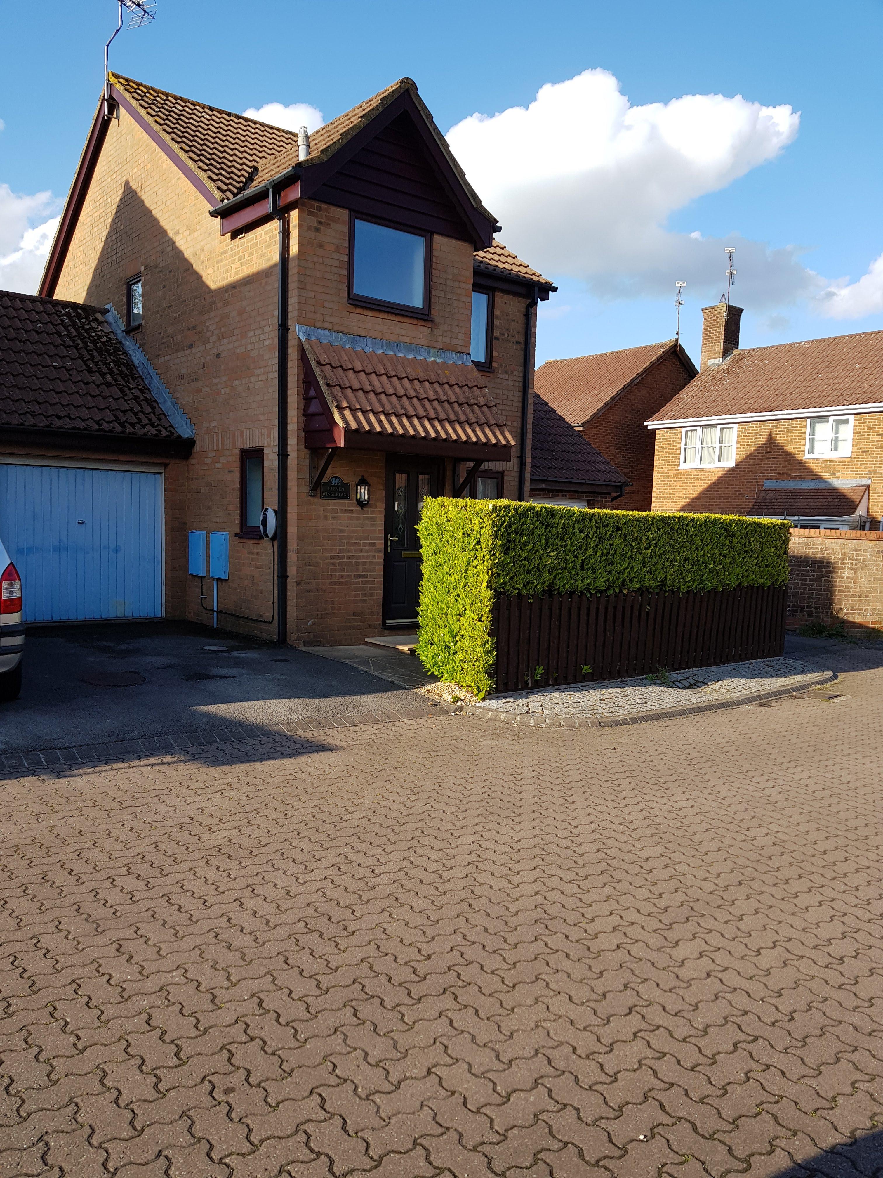
What other models would be useful to a visually impaired person? It occurred to me that despite the fact we have lived in our house for over 30 years, Sue had no real appreciation of the outside shape of the building. I decided to create a 3D model of the house to remedy this.
The resulting model has allowed Sue to gain a real understanding of the place where she lives.
This Instructable describes the process of producing the 3D files using free design software and the printing of a miniature version of our house.
This was my entry in the Big vs Small Challenge - and it won a First Prize! Many thanks to everyone that took an interest in this project.
Edit 28/09/21: I have just published an Instructable describing the transformation of a magnifying lamp into the starship Enterprise! Please take a look: 'Enterprising' Magnifying Lamp Upgrade : 9 Steps (with Pictures) - Instructables
Produce a Dimensioned Drawing of the House
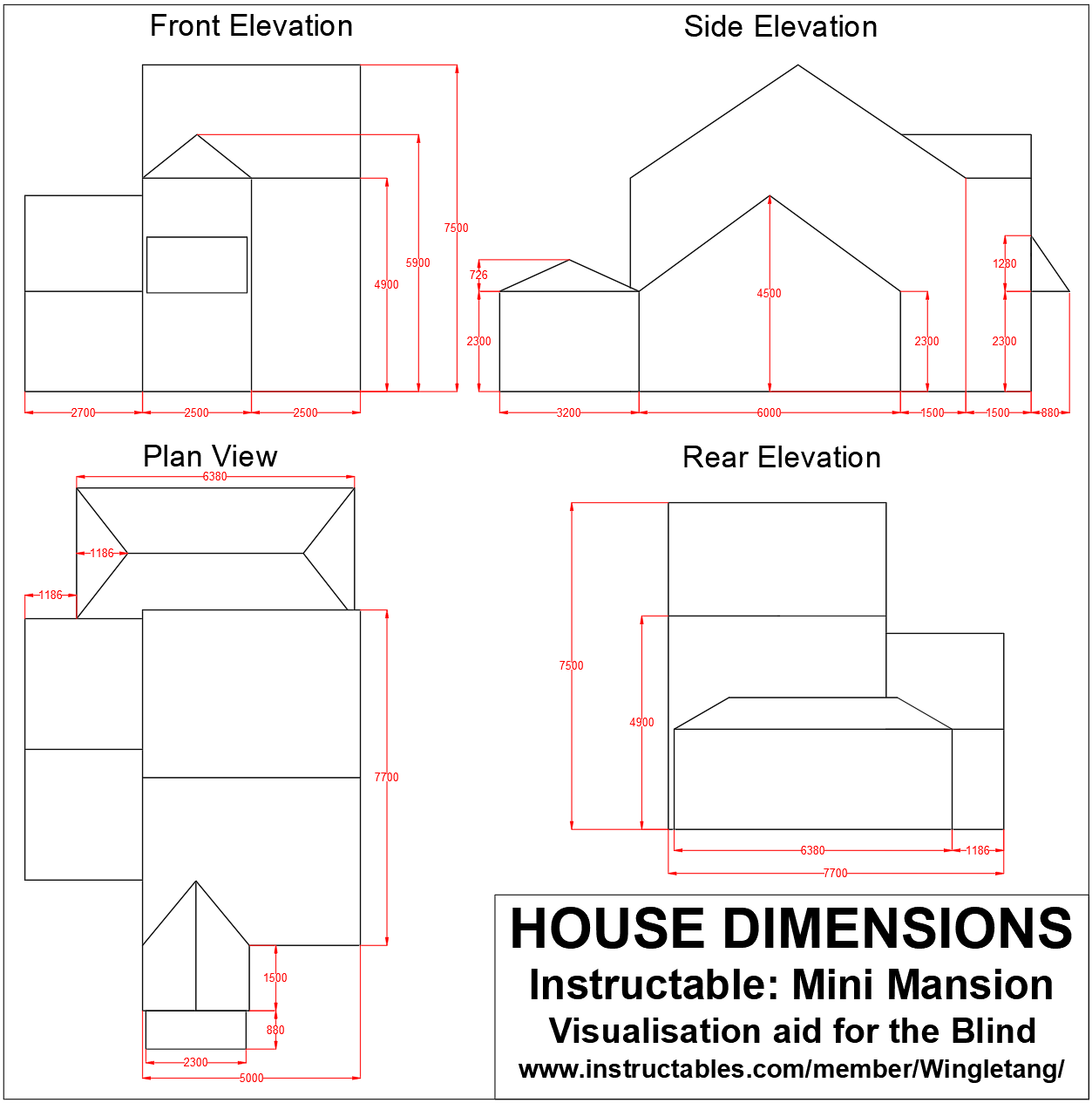
The first requirement was to produce a drawing of our house with dimensions.
A few years ago we added a conservatory (garden room) to the building and the designer produced drawings with many of the required measurements. Using this as a starting point, and measuring the missing dimensions myself, I produced the attached drawing using AutoCAD LT 2022.
The drawing has sufficient dimensions to allow a model of the house to be produced.
Splitting the House Into Simple Blocks
The next step is to work out how the house can be split into simple blocks that can be created individually in the 3D software.
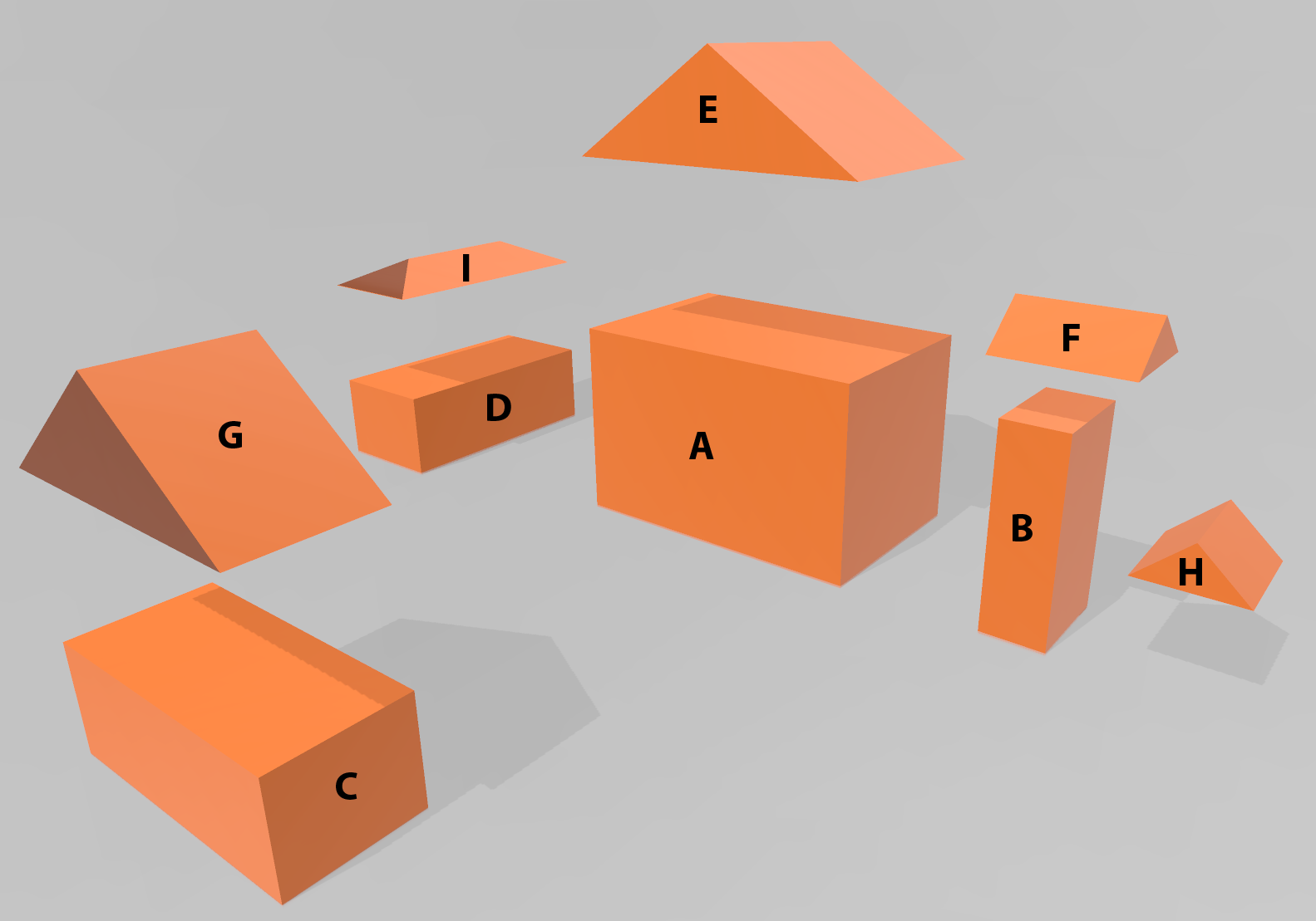
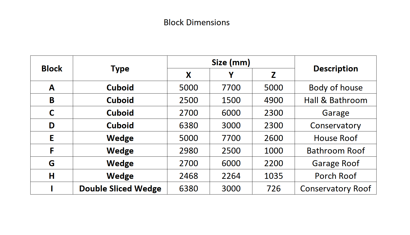
The first picture shows an exploded view of these blocks. Nine blocks are required:
A-D are cuboids (stretched cubes)
E-H are wedges
I is a wedge that has had the ends sliced off at an angle to produce the conservatory roof shape.
The dimensions of the blocks are shown in the table in millimetres.
Creating the Cuboids in Microsoft 3D Builder
Microsoft 3D Builder is a simple 3D design program available for free here: Microsoft 3D Builder
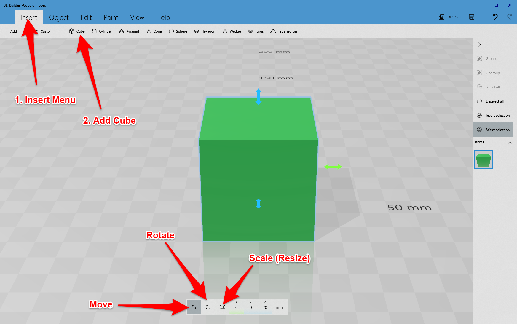
To create a cuboid in 3D Builder:
Click New Scene.
Click the Insert menu and select Cube - First picture.
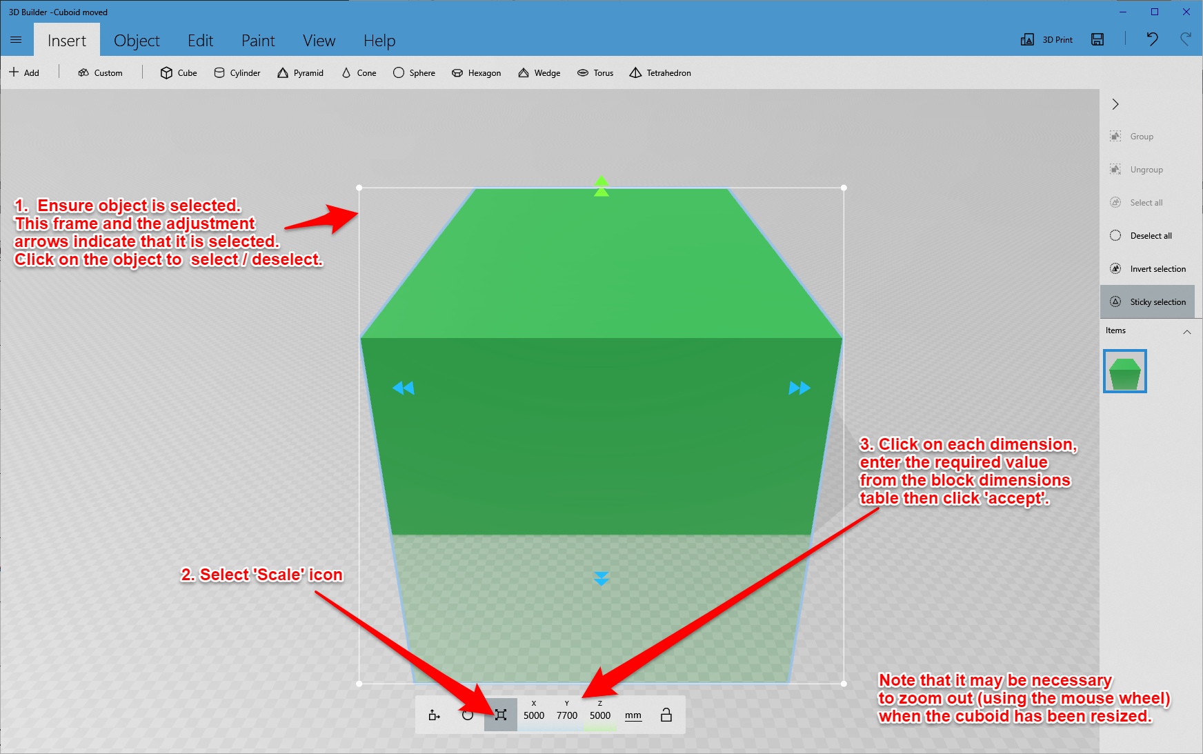
Click the Scale icon at the bottom of the screen (square with arrows pointing away from the corners).
Enter the dimensions of cuboid A in the X, Y and Z fields.
Use the mouse wheel to zoom out - Picture 2.
Note that the scene can be 'orbited' by positioning the pointer on the background grid (i.e. not on any object) then clicking and holding the left mouse button while moving the mouse. Similarly, the scene can be panned in the same way but also holding the Ctrl key. These moves require some practice.
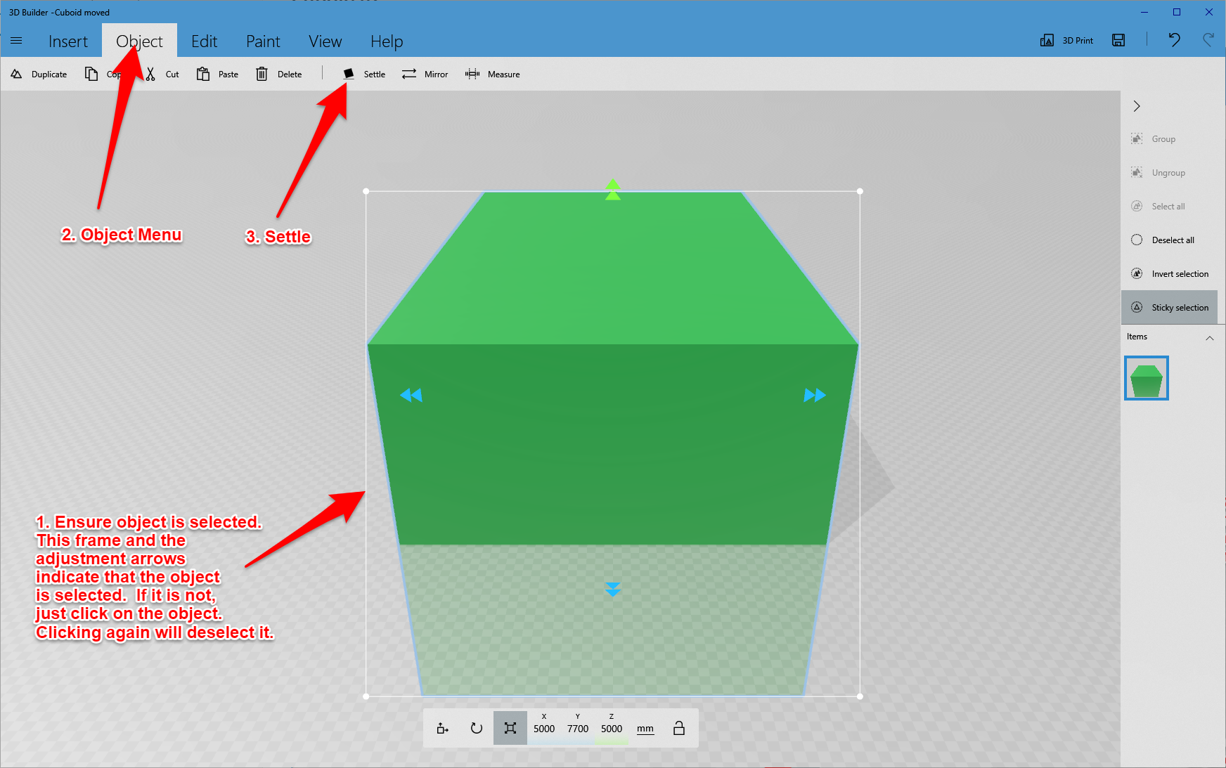
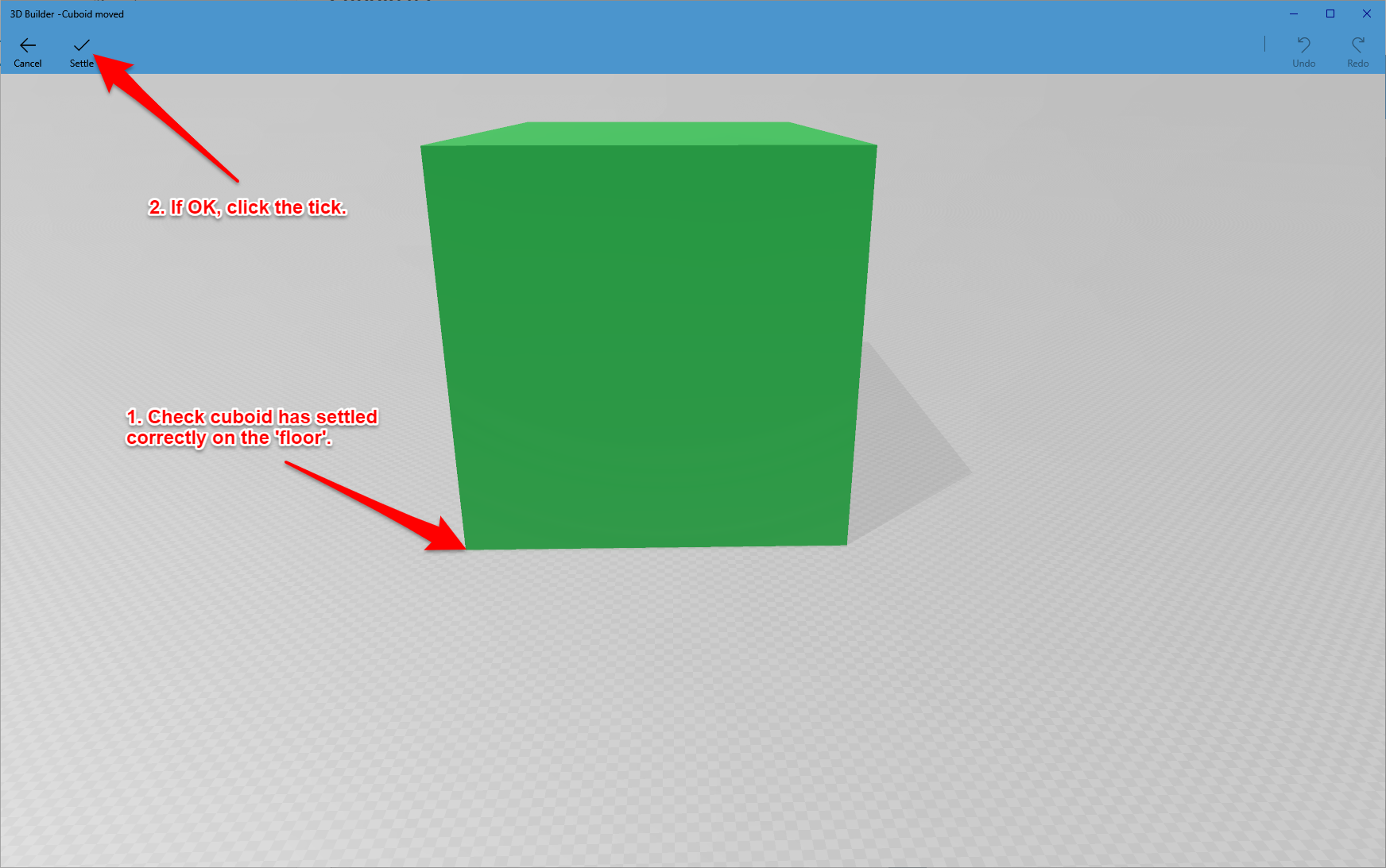
The resulting cuboid will have the correct dimensions, but the object will be half way into the 'floor' - Picture 3.
To correct this, click the Object menu (with the cuboid selected) and click Settle. The cuboid will be repositioned on the floor. If all looks OK, click the tick at the top of the screen - Picture 4.
Move cuboid A out of the way ready for the next cuboid. Do this by selecting the Move icon and then dragging the horizontal adjustment arrow.
Alternatively, just click and hold the object and drag it with the mouse but be careful not to distort the cuboid (especially if the scale icon is selected as it is easy to resize by accident).
Hint - after carrying out any operation, always click the Deselect All button at the right hand side of the window. If this is not done, operations intended for one object can be applied to others that are still selected. If the Sticky Selection option is active it is possible to select several objects simultaneously.
Save the scene so far by clicking on the '3 horizontal lines' menu at the top left and select 'save as'. The file format is .3mf (3D Manufacturing Format).
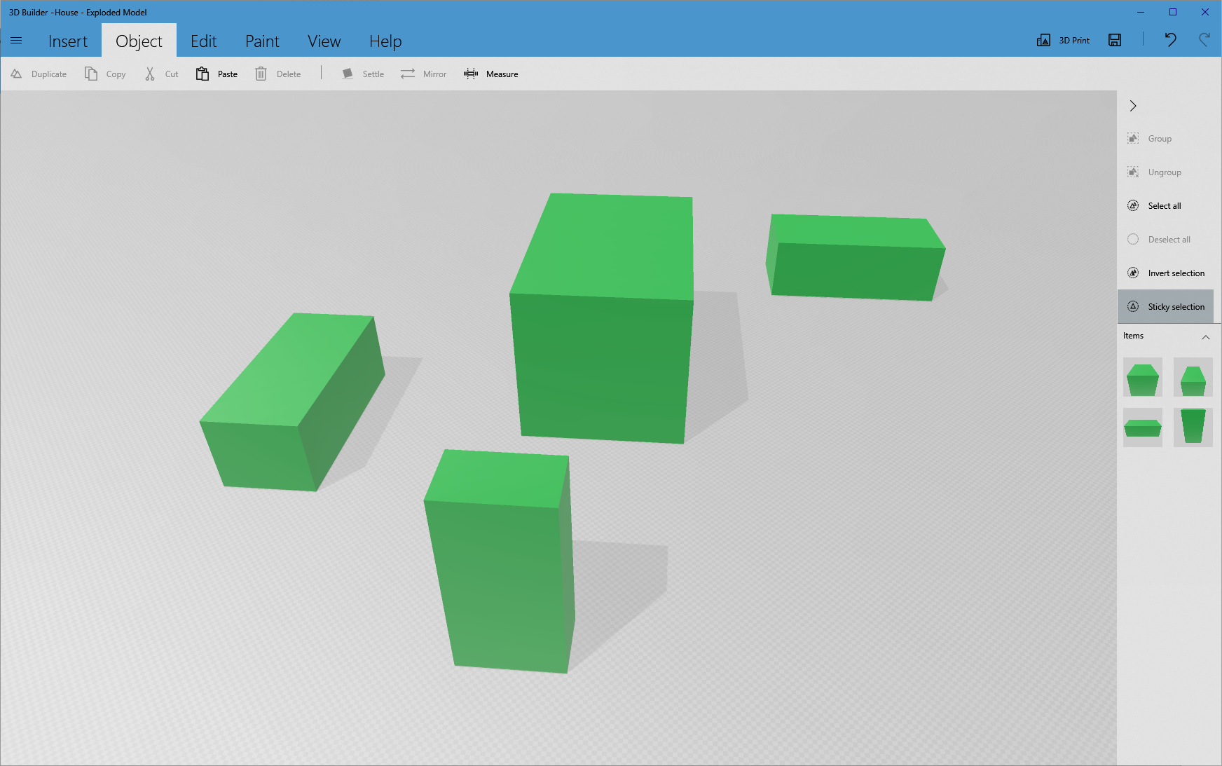
Repeat the above steps for the other cuboids. When finished it should look like Picture 5.
Creating the Wedges in Microsoft 3D Builder
Creating the wedges is the same process except that a wedge is inserted in the first step - Picture 1.
Create all of the wedges.
Note that the bathroom roof wedge will have to be rotated through 90 degrees. With the wedge selected, click the rotate icon and enter 90 as the Yaw value.
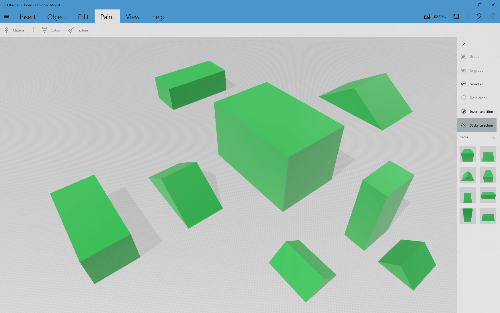
The final collection of wedges and cuboids should look like Picture 2.
Creating the Conservatory Roof
The conservatory roof starts out as a wedge and then the two sloping ends are sliced from it.
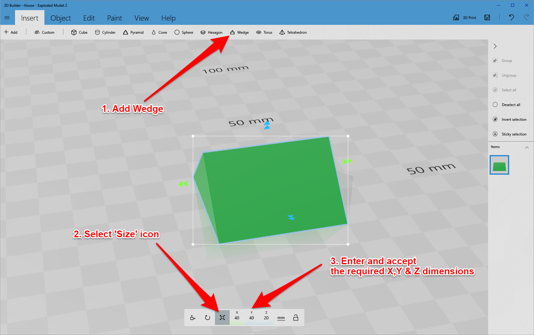
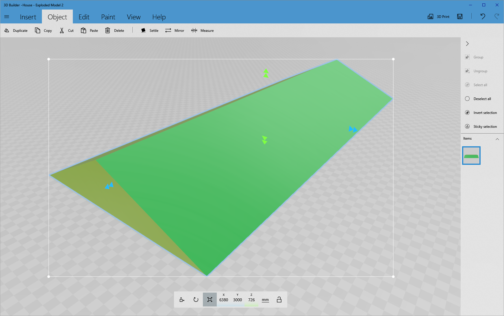
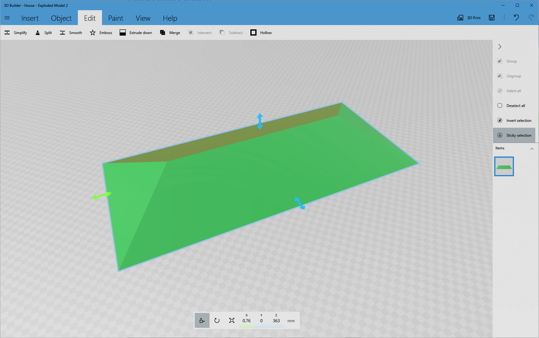
Insert a wedge, select the Size icon and enter the required dimensions from the table - Picture 1.
Splitting the wedge
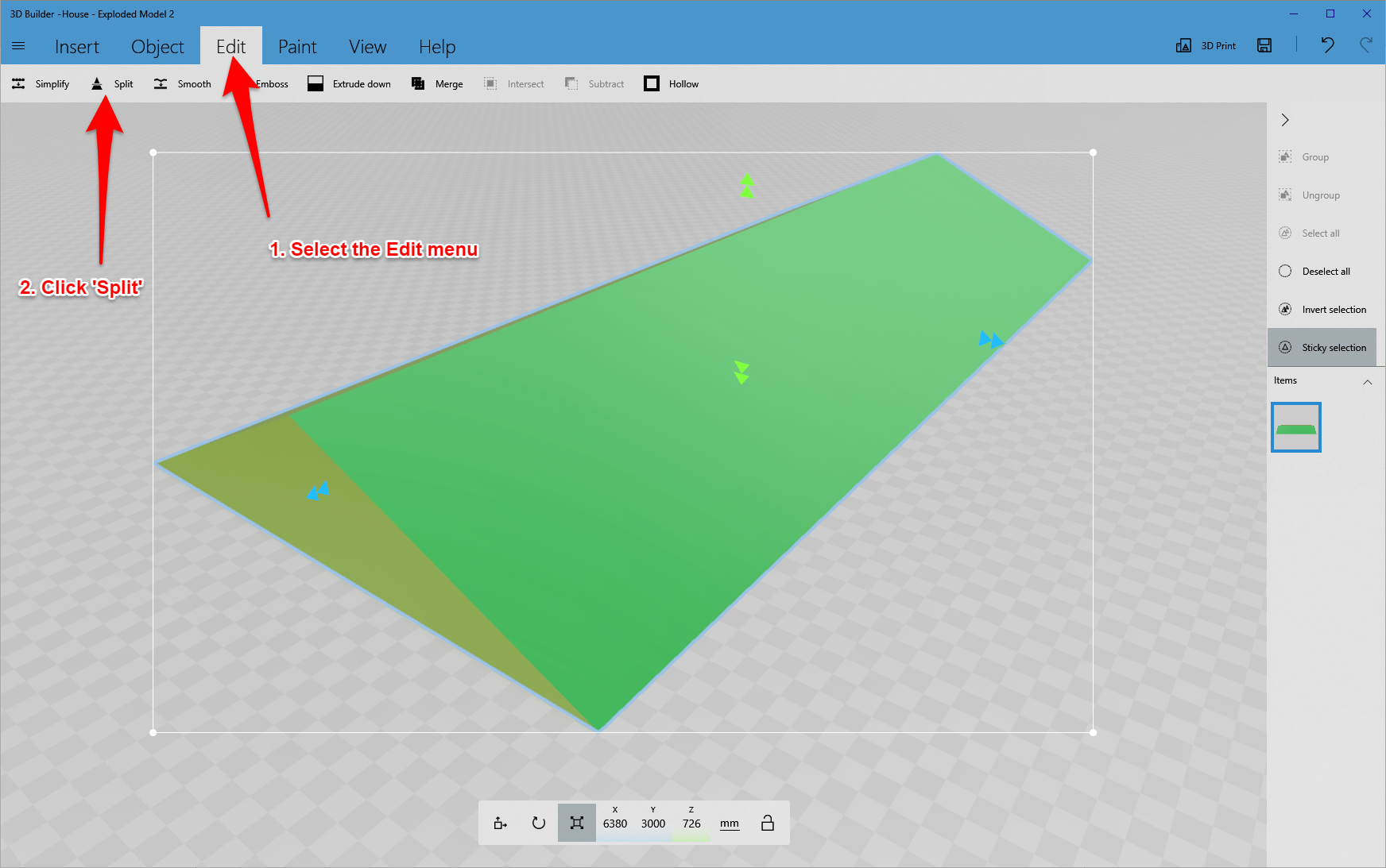
With the wedge selected activate the Edit menu and click Split - Picture 2.
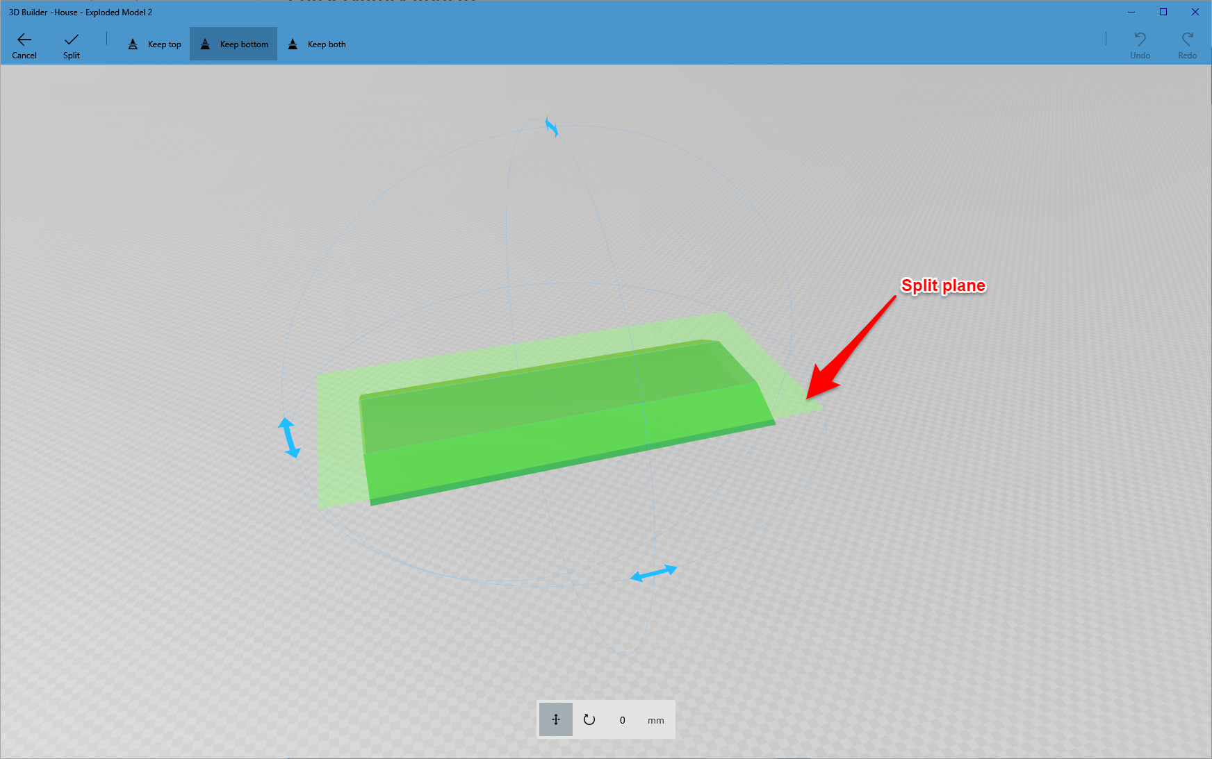
A green plane will appear showing the split position - Picture 3.
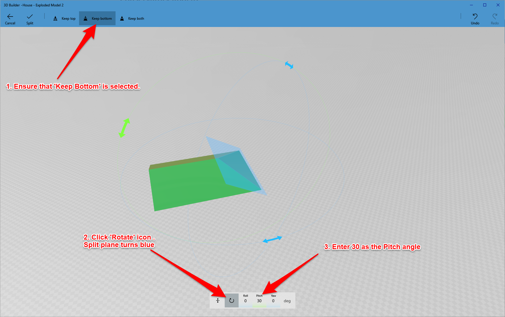
Ensure that Keep Bottom is selected at the top of the screen - this determines which part of the object will be kept after the split.
Click the rotate icon at the bottom of the screen. At this point, it is the rotation of the split plane that will be carried out. The plane is coloured blue to indicate that rotation is active.
Enter and accept 30 degrees as the pitch value - Picture 4.
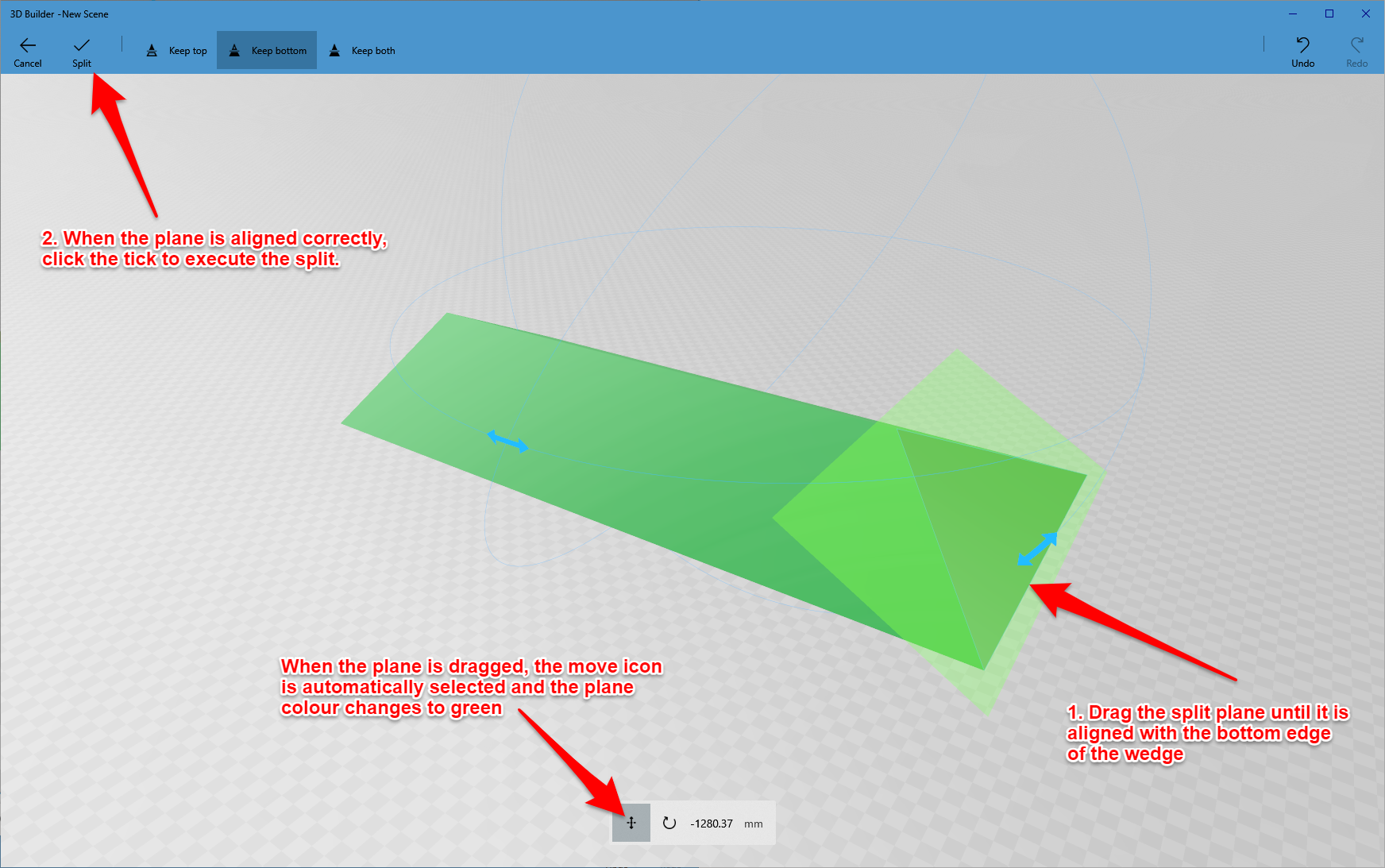
The plane now needs to be moved to the end of the wedge. Put the mouse pointer on the plane - the pointer becomes a hand symbol. Drag the plane to the right hand end of the wedge so that it aligned with the bottom edge. The move icon is automatically selected during the drag and the plane becomes green - Picture 5.
When the plane is correctly aligned, click the tick at the top of the screen to execute the split - Picture 6.
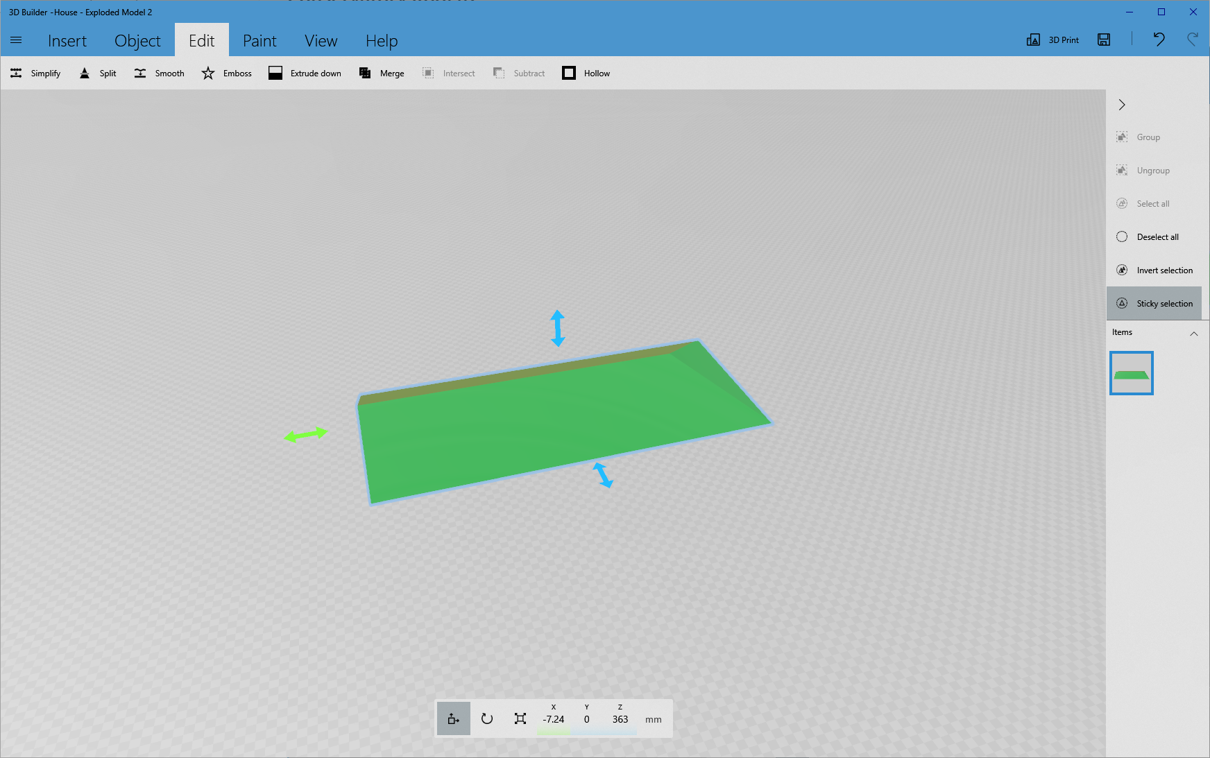
Repeat the steps above (from 'Splitting the Wedge') to slice off the other end of the wedge. The only difference is that the pitch of the split plane must be set to -30 degrees.
The final object should look like Picture 7.
Assembling the House
Now we have all of the blocks to make up the house.
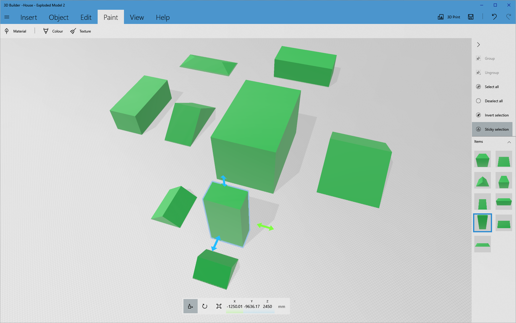
To assemble the model, select a block by clicking on it and check that the move icon is selected at the bottom of the screen - Picture 1.
Move it to the required position against another block by dragging the position arrows - Picture 2.
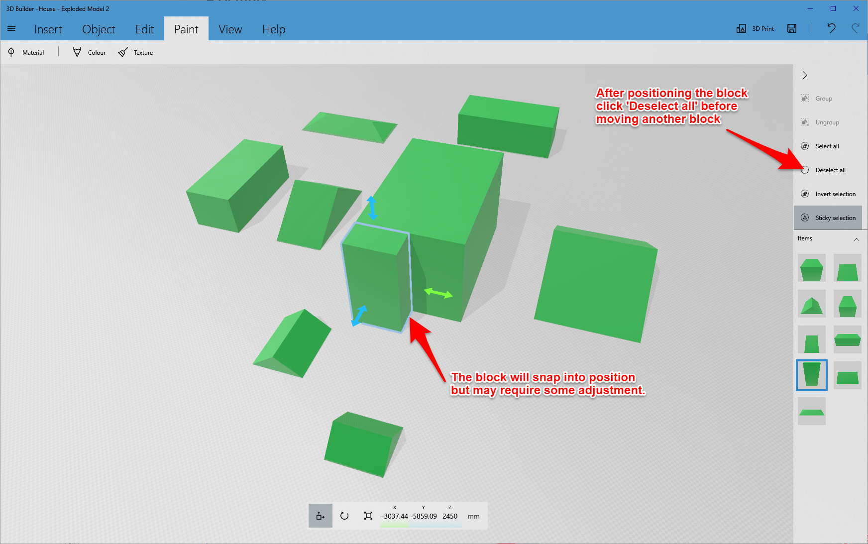
In most cases the blocks will snap together but make sure that each block is positioned correctly.
After positioning a block, click the Deselect All button at the right hand side of the screen. If this is not done, it is easy to inadvertently move more than one block.
If a block is not aligned with a corner, it can be accurately positioned as follows.
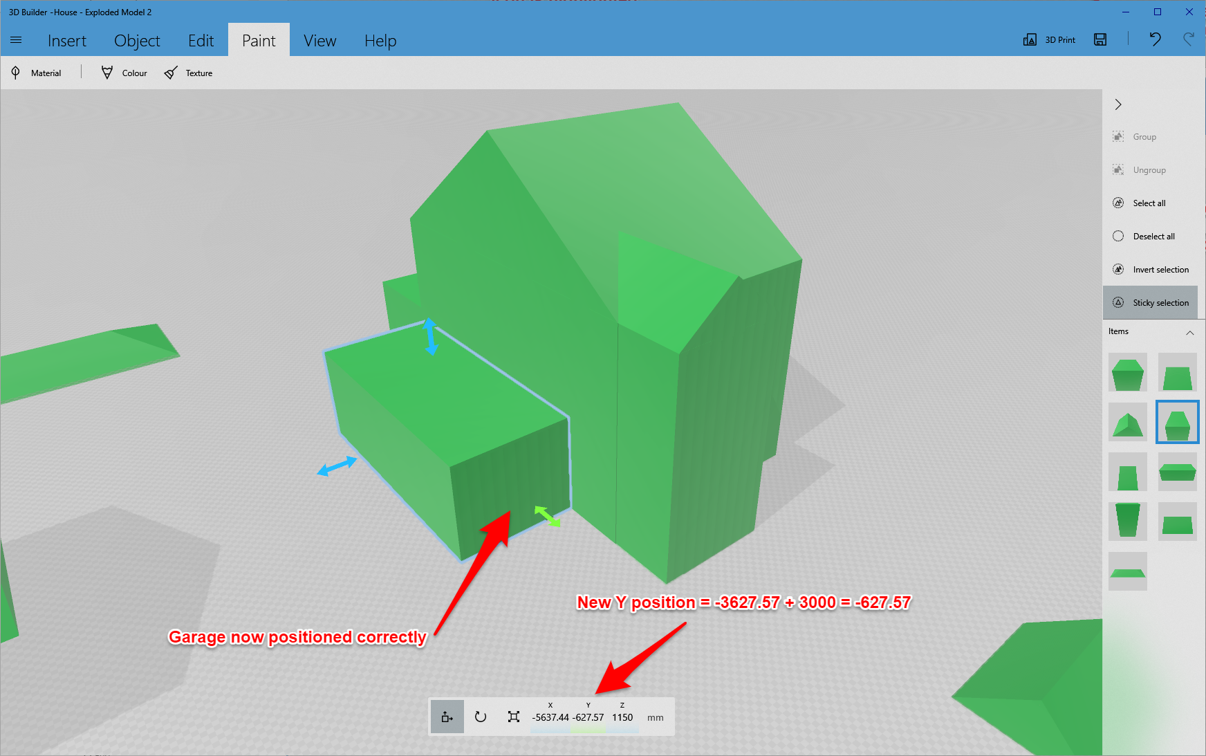
For example, consider the garage block.
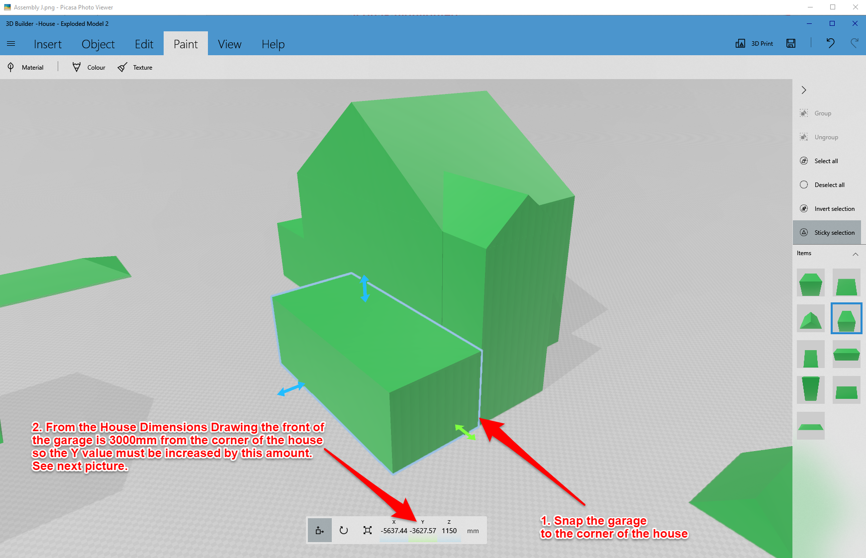
Initially position this at the front corner of the house - Picture 3.
From the House Dimensions Drawing it can be seen that the front of the garage is 3000mm from the front corner of the house. To achieve this, edit the Y position by subtracting 3000mm from the current value. The garage block will move into the correct position - Picture 4.
The same positioning technique is required for the Conservatory (X position) and Porch Roof (Z position).
Note that the Porch roof, Bathroom roof and Conservatory roof blocks all intersect with other objects. For example, the porch roof is a complete wedge but half of it buried in the adjacent block. This does not matter as the 3D slicing software simplifies the model to ignore such intersections.
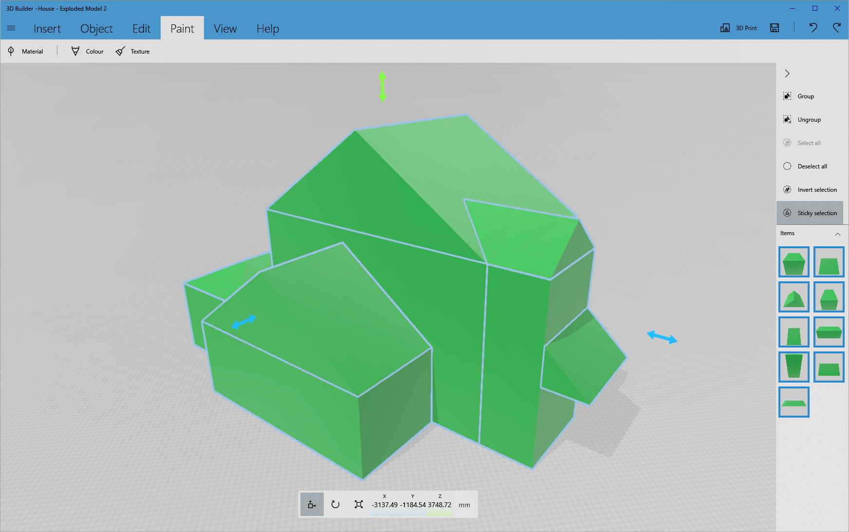
The assembled model is shown in Picture 5.
Save the model as a 3mf file.
Windows and Doors
The purpose of the final 3D printed model is to give Sue a good understanding of the shape of the house, but she did request that the Windows and doors were also indicated.
While highly detailed versions of the doors and windows would look good, these are not necessary for a tactile 'overview' model. We decided that simple rectangular depressions would suffice.
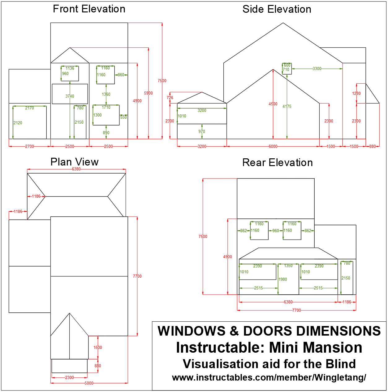
The first step was to add the doors and windows to the House Dimensions Drawing. After several hours with a tape measure and a notebook the attached drawing was produced.
Subtracting the Windows and Doors
'Surely you mean Adding the Windows and Doors?'
Not in this case.
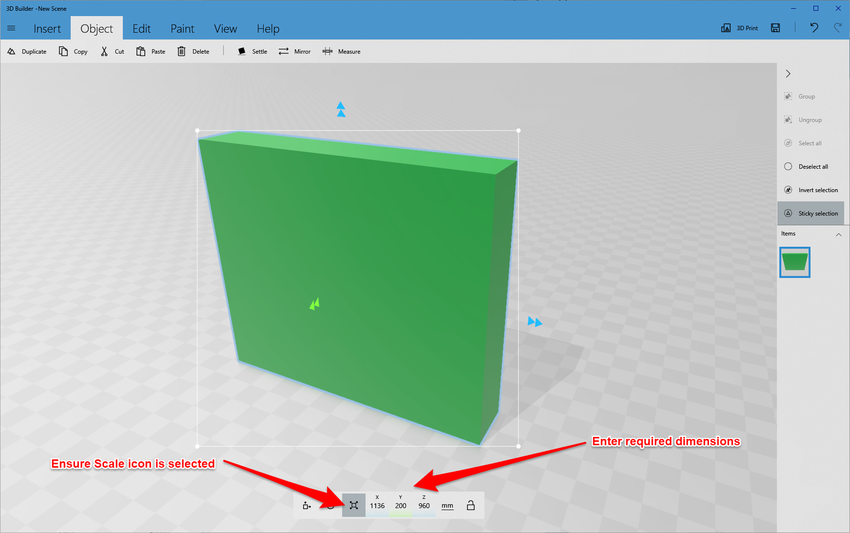
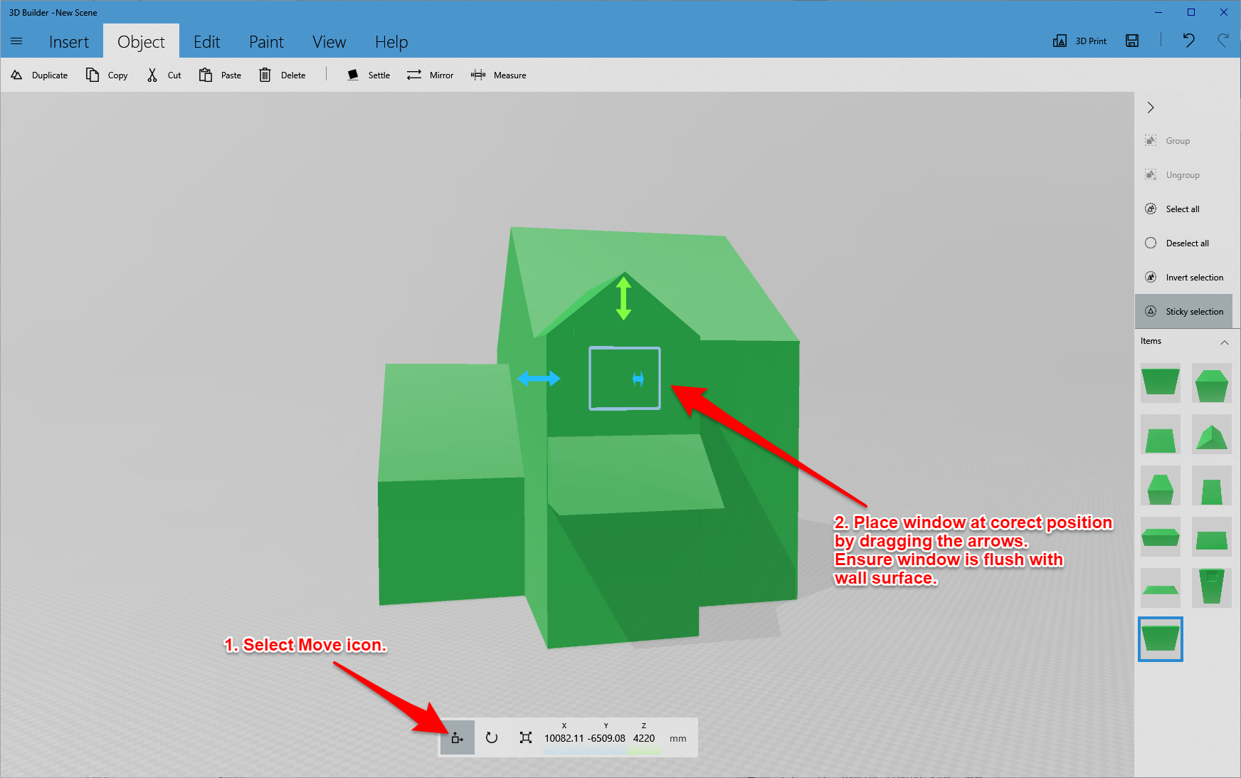
The procedure will be to create a cuboid with the width and height of a window or door and a thickness of 200mm. This is then placed in the correct position flush to the surface of the relevant block. The window cuboid is then stretched so it is proud of the other blocks surface. The window cuboid is then Subtracted from the model leaving the required rectangular depression.
As an example consider the bathroom window.
Create a cuboid with the dimensions X=1136mm, Y=200mm Z=960mm - Picture 1.
Position this above the Porch roof, 3740mm from the floor. It will snap centrally. Make sure the front surface is flush with the front wall - Picture 2.
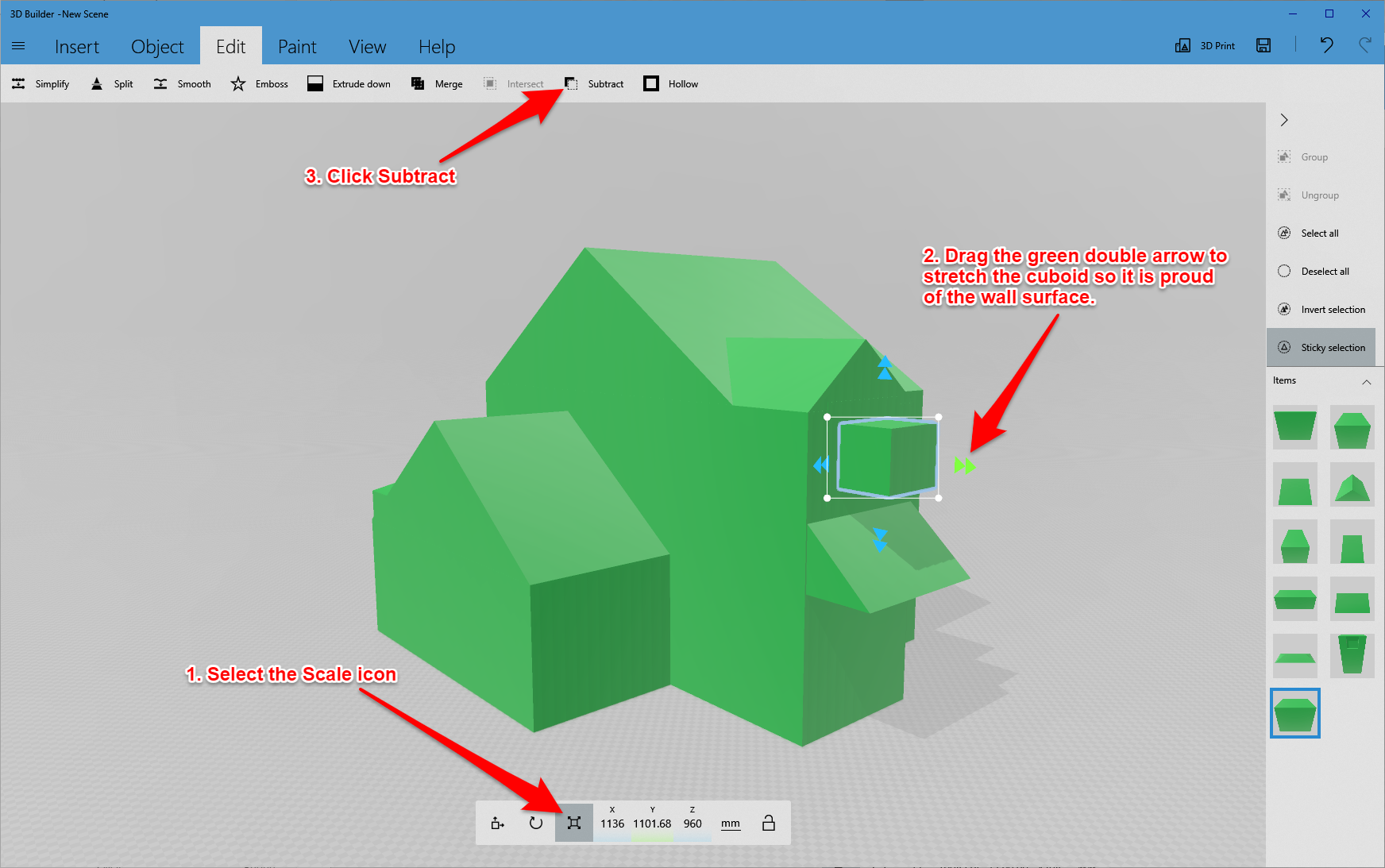
Click on the scale icon and stretch the front face of the window cuboid so it protrudes through the wall - Picture 3.
This is necessary as subtracting a flush object sometimes leaves a thin sheet over the front of the depression
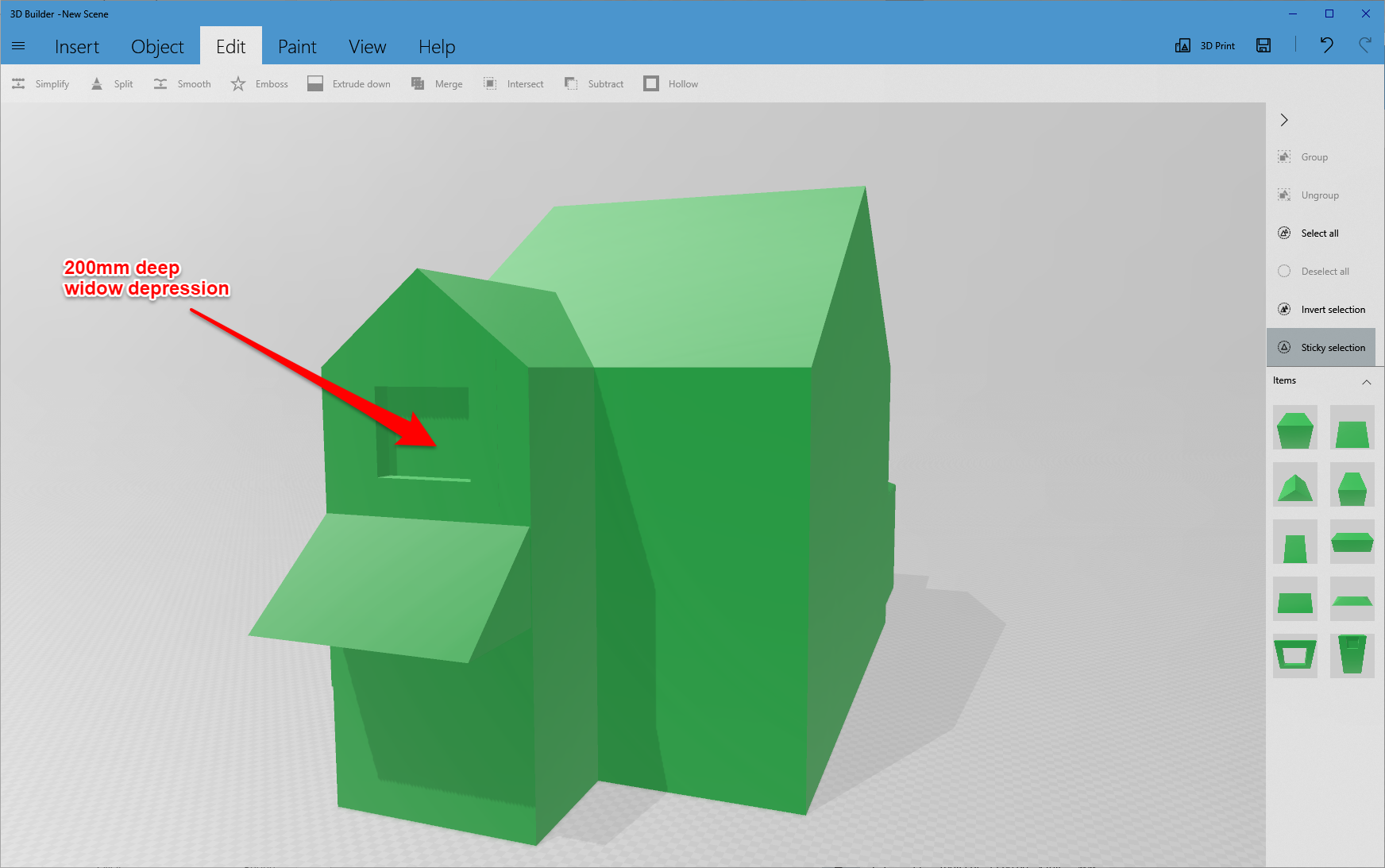
Click the Edit Menu and select Subtract. The cuboid will be subtracted leaving the desired 200mm deep window depression - Picture 4.
Repeat this for all of the other windows and doors.
Note that some of the window blocks will have to be rotated through 90 degrees. Select the block, click the rotate icon and enter 90 as the Yaw value.
Hint - only one selected object can be subtracted at a time.
The resulting model is shown in pictures 5 and 6.
Save the model as a 3mf file.
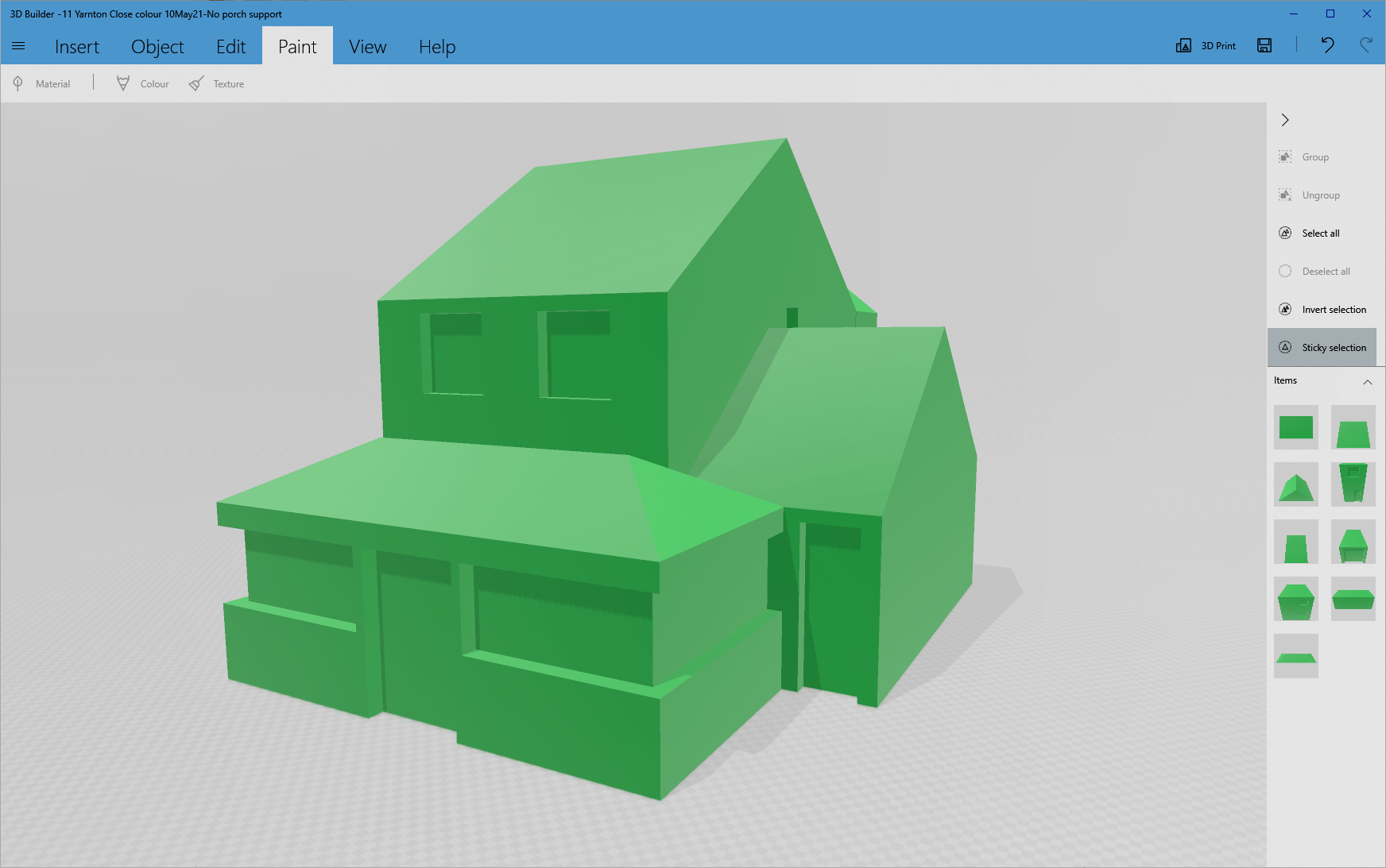
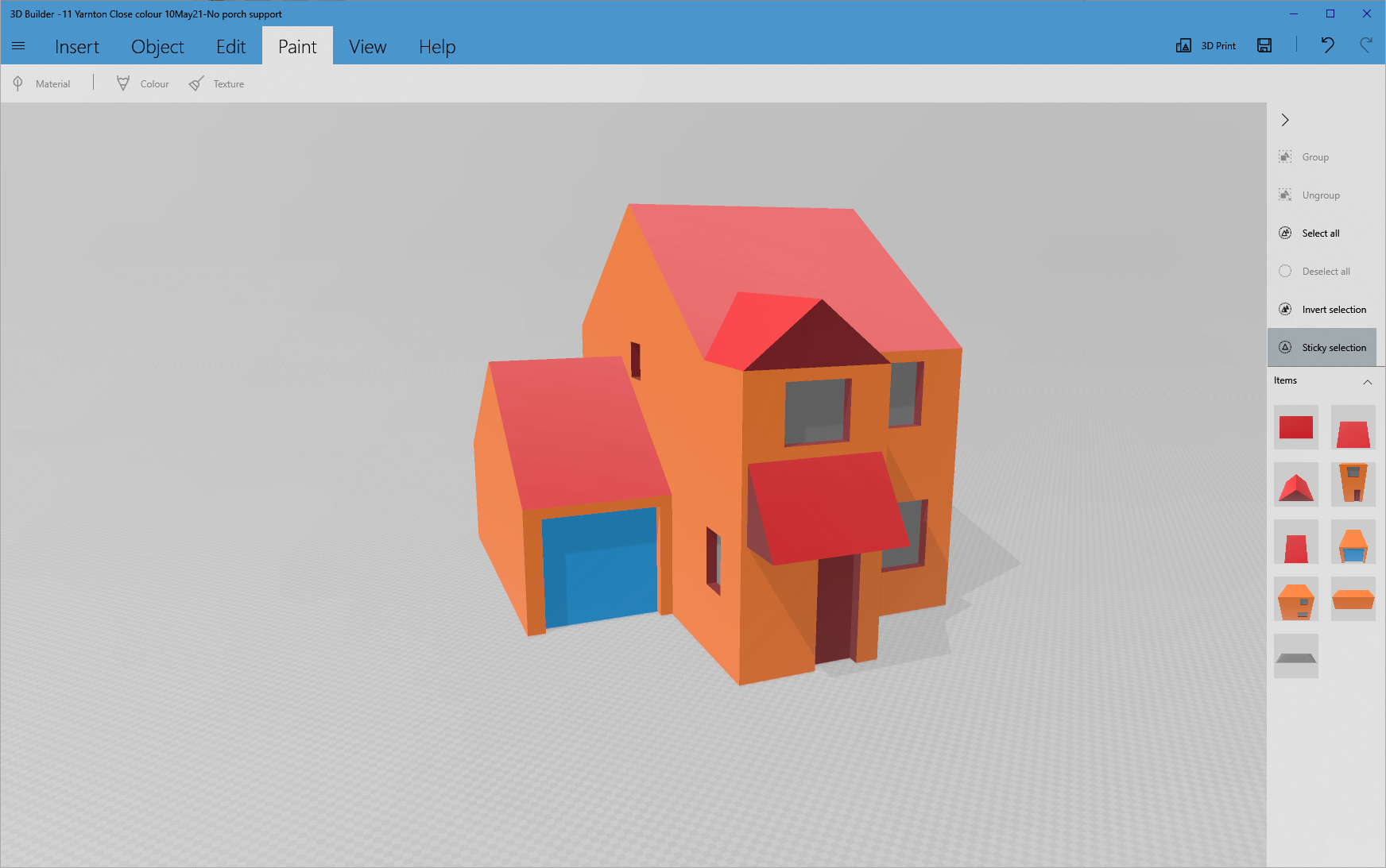
Painting the Model (Optional)

If desired, the model can be painted.
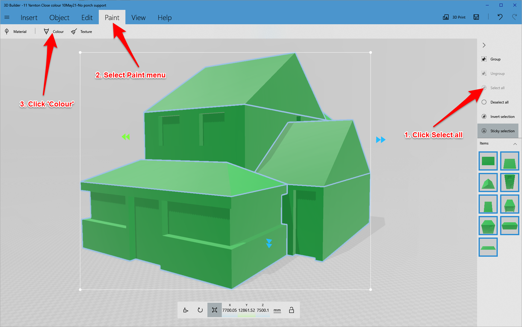
Click Select all at right hand side of screen - Picture 1.
Select the Paint menu.
Click on the Selected menu and chose / create the desired colour (e.g. orange for the brickwork).
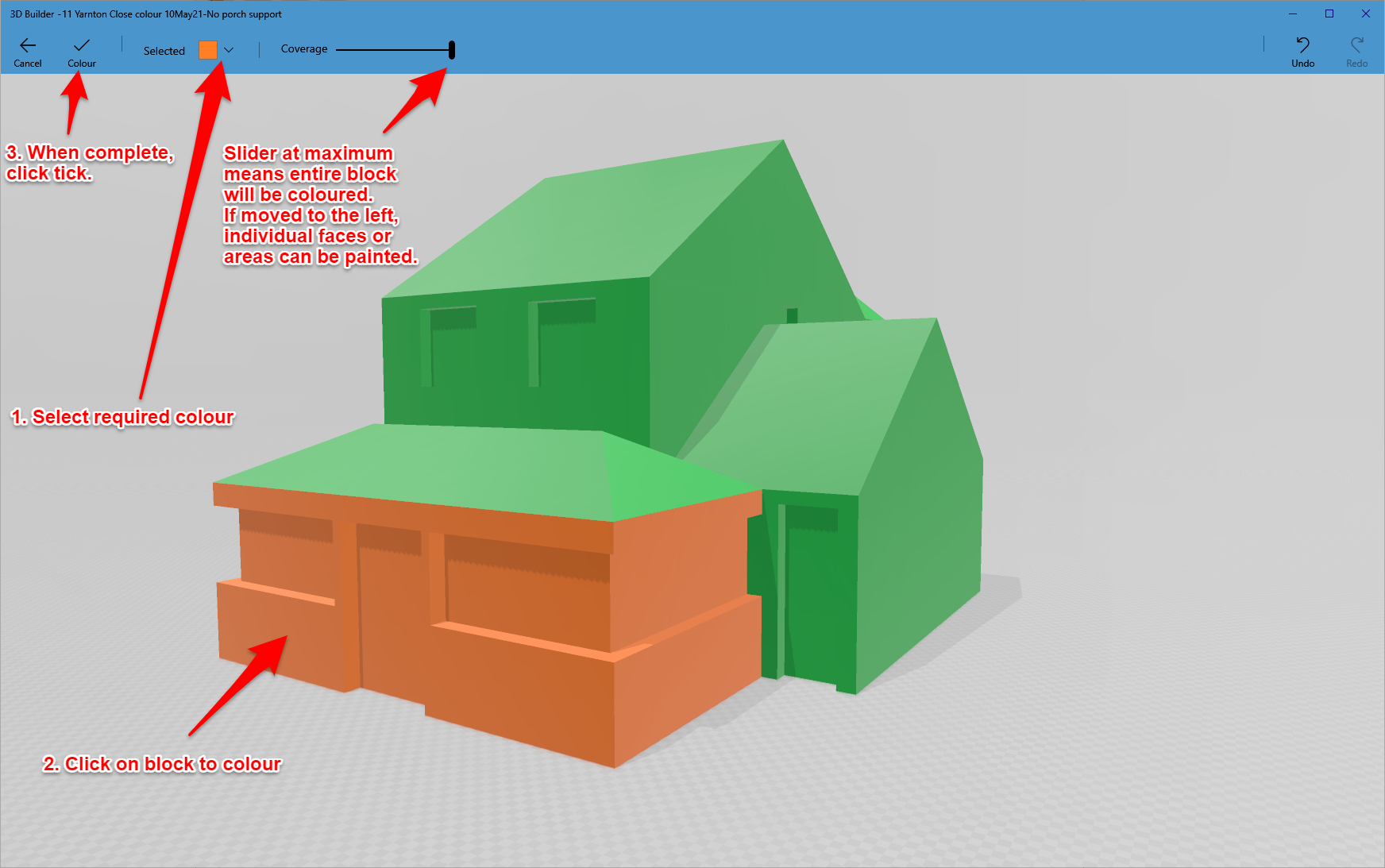
Click the mouse on the blocks you wish to colour - Picture 2.
Select another colour (e.g. red for the roof).
Note that the slider determines how much is painted with each click. Slider fully to the right means that the entire block will be coloured.
Moving the slider to the left allows individual faces to be coloured.
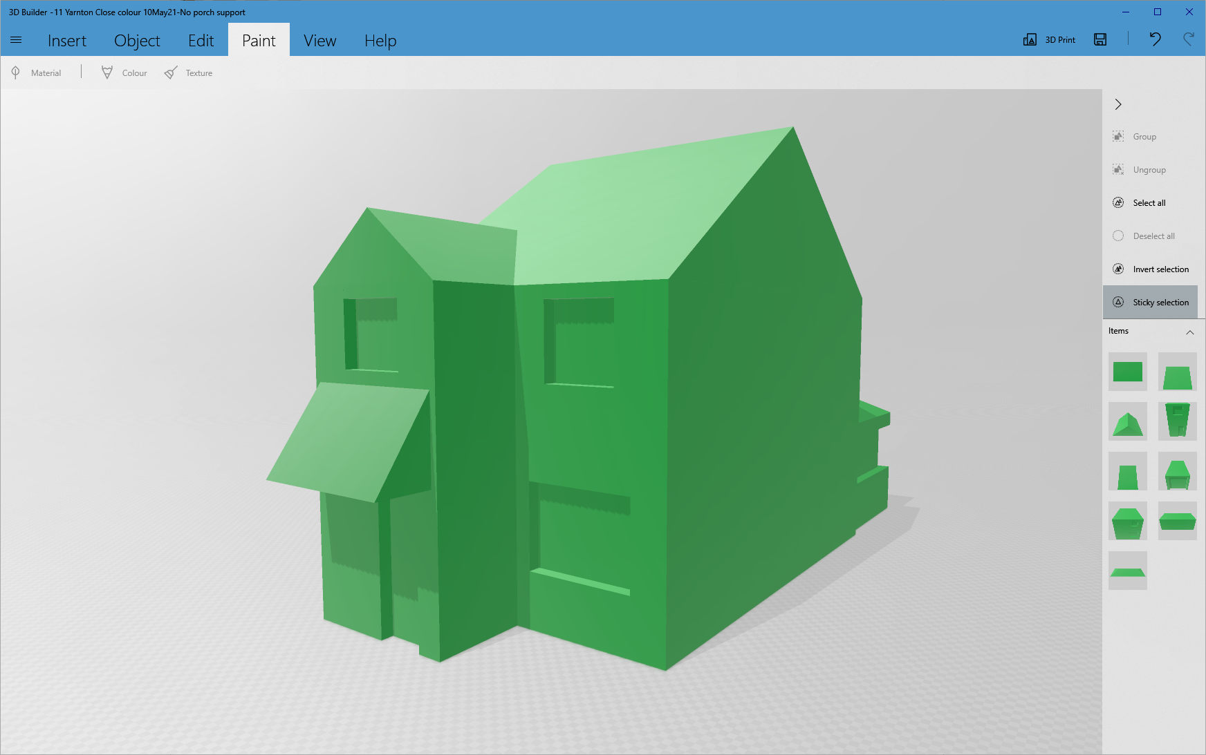
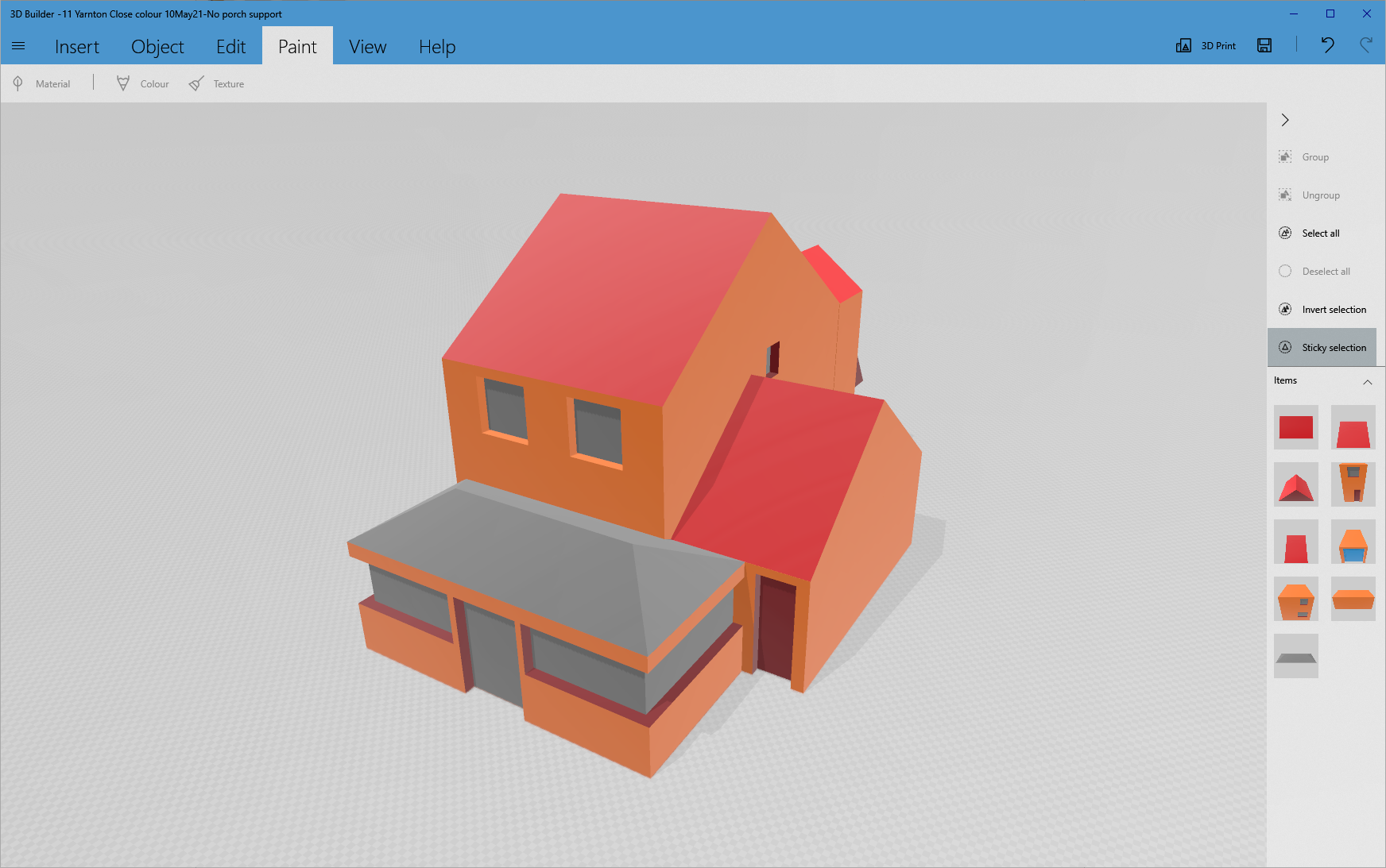
The last two pictures shows the fully painted model.
Do not forget to save your model as a 3mf file. I attach my coloured 3mf file that you can load into 3D Builder or Prusa Slicer.
Downloads
Preparing the Model for 3D Printing
I use a Prusa i3 Mk2 3D printer.
Prusa publishes an excellent 'slicing' program that converts .3mf (and other 3D format) files into 'G Code'. This code is saved onto an SD card that can then be plugged into the printer to allow the model to be 3D printed.
Download Prusa Slicer from here: https://www.prusa3d.com/drivers/
Run the program and load the .3mf file of the house (File Menu, Open Project).
A dialogue may appear:
This file contains several objects at multiple heights. Instead of considering them as multiple objects, should I consider this file as a single object having multiple parts?
Click Yes.
Another dialogue will appear:
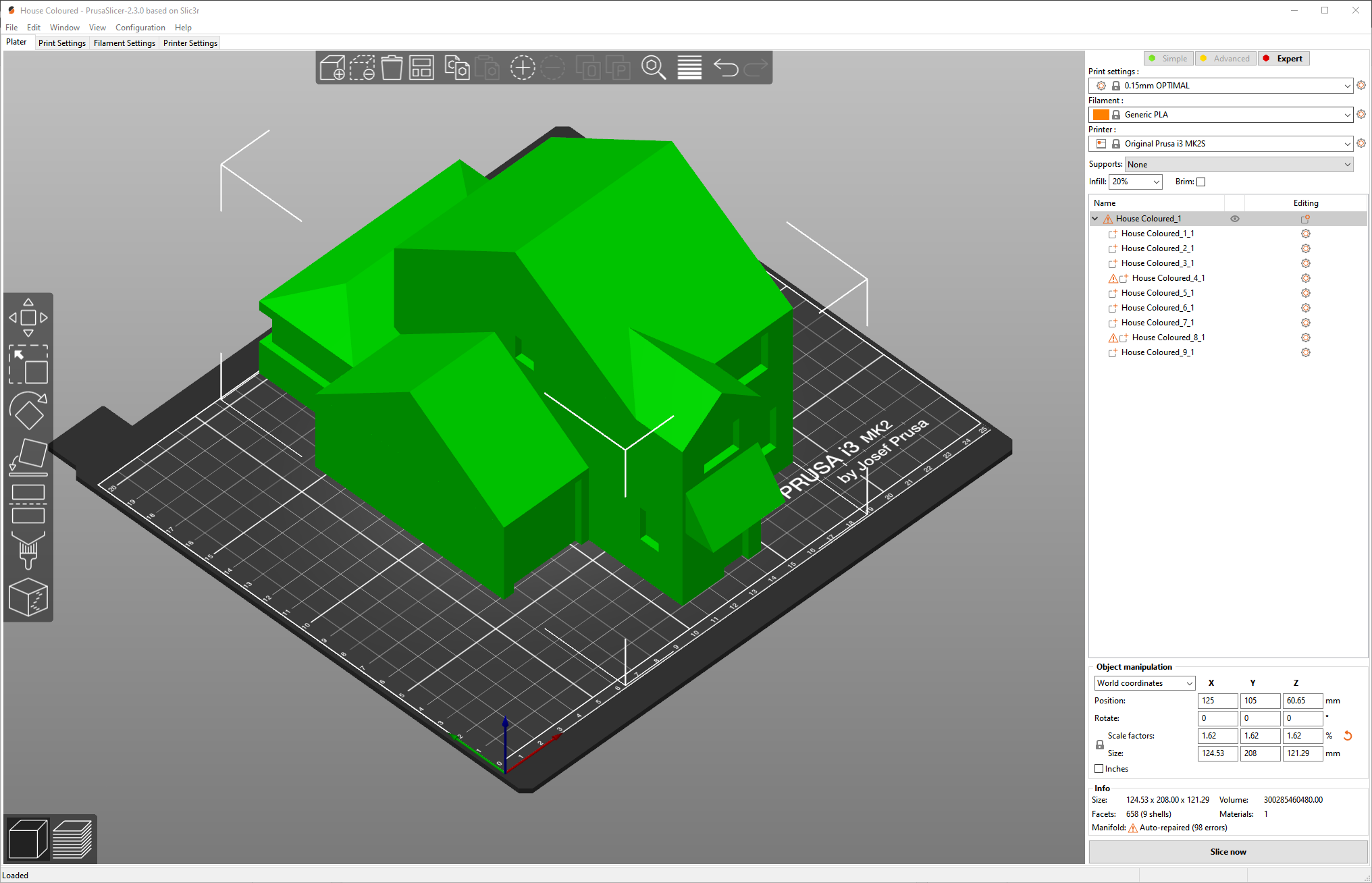
Your object appears to be too large, so it was automatically scaled down to fit your print bed.
This is because our model was constructed at full size. Click OK.
A scaled down version will appear - Picture 1.
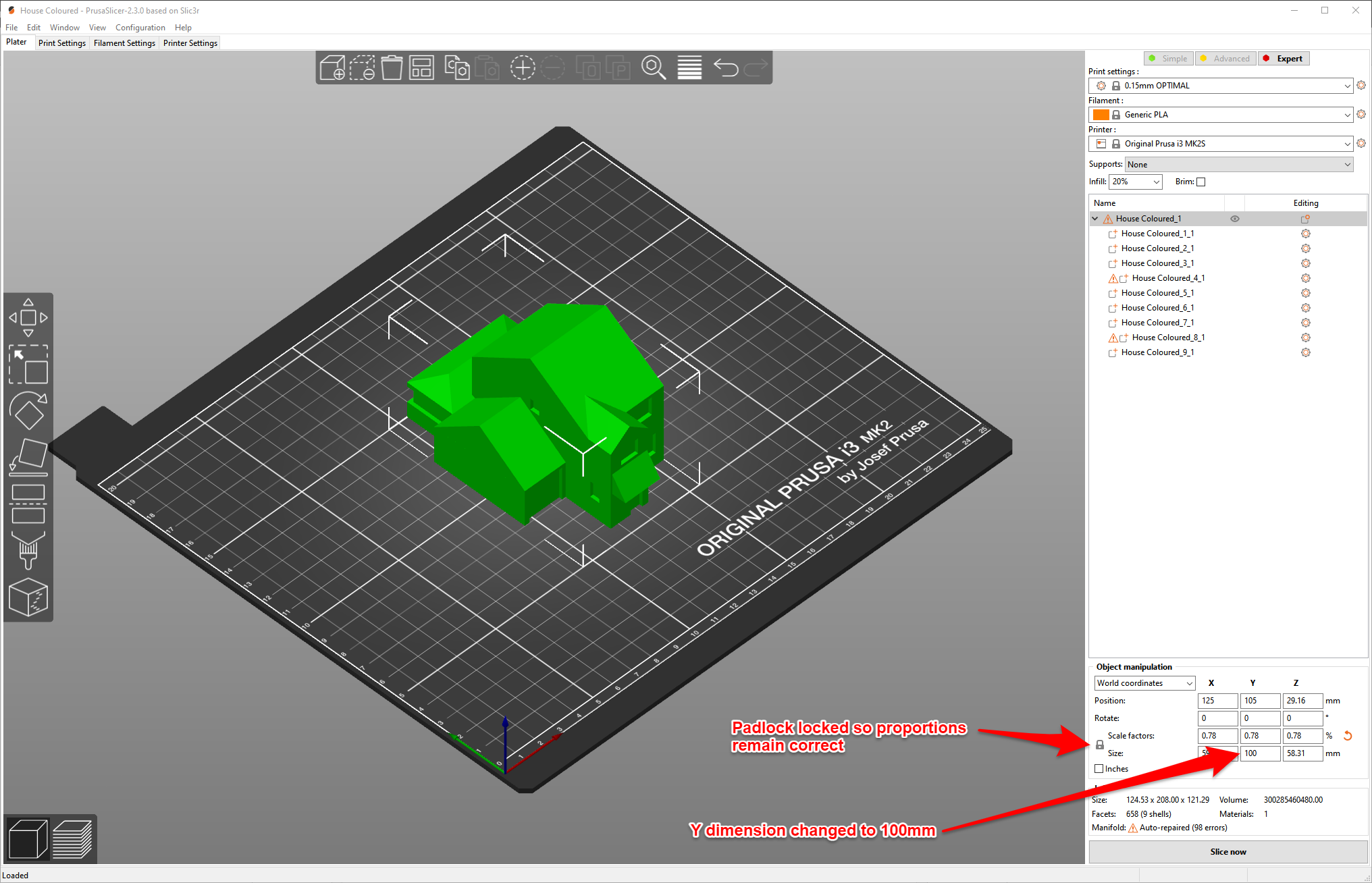
This is still too big for our purpose so the size should be adjusted to the required value. A model measuring 10cm front to back is suitable so change the Y size to 100mm - Picture 2.
As long as the padlock symbol to the left of the Scale factors and sizes is locked, the X and Z sizes are automatically adjusted to maintain the model proportions.
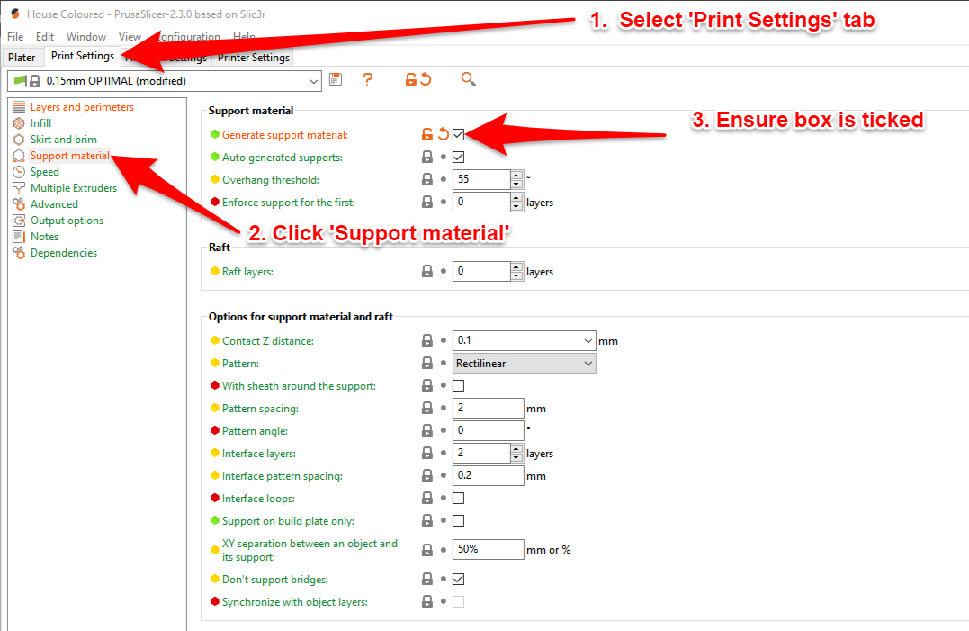
As the model has horizontal projections (such as the porch roof) support material ('scaffolding') will have to be printed to prevent sagging. The support material can be broken away easily after printing.
Click the Print Settings tab and select Support Material on the left hand side.
Tick the Generate Support Material box - Picture 3. A dialogue will appear
Supports work better, if the following feature is enabled - Detect bridging parameters. Shall I adjust those settings for supports?
Click Yes.
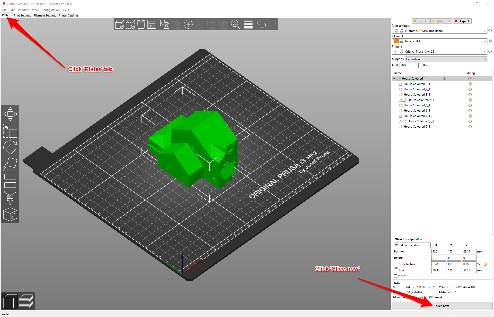
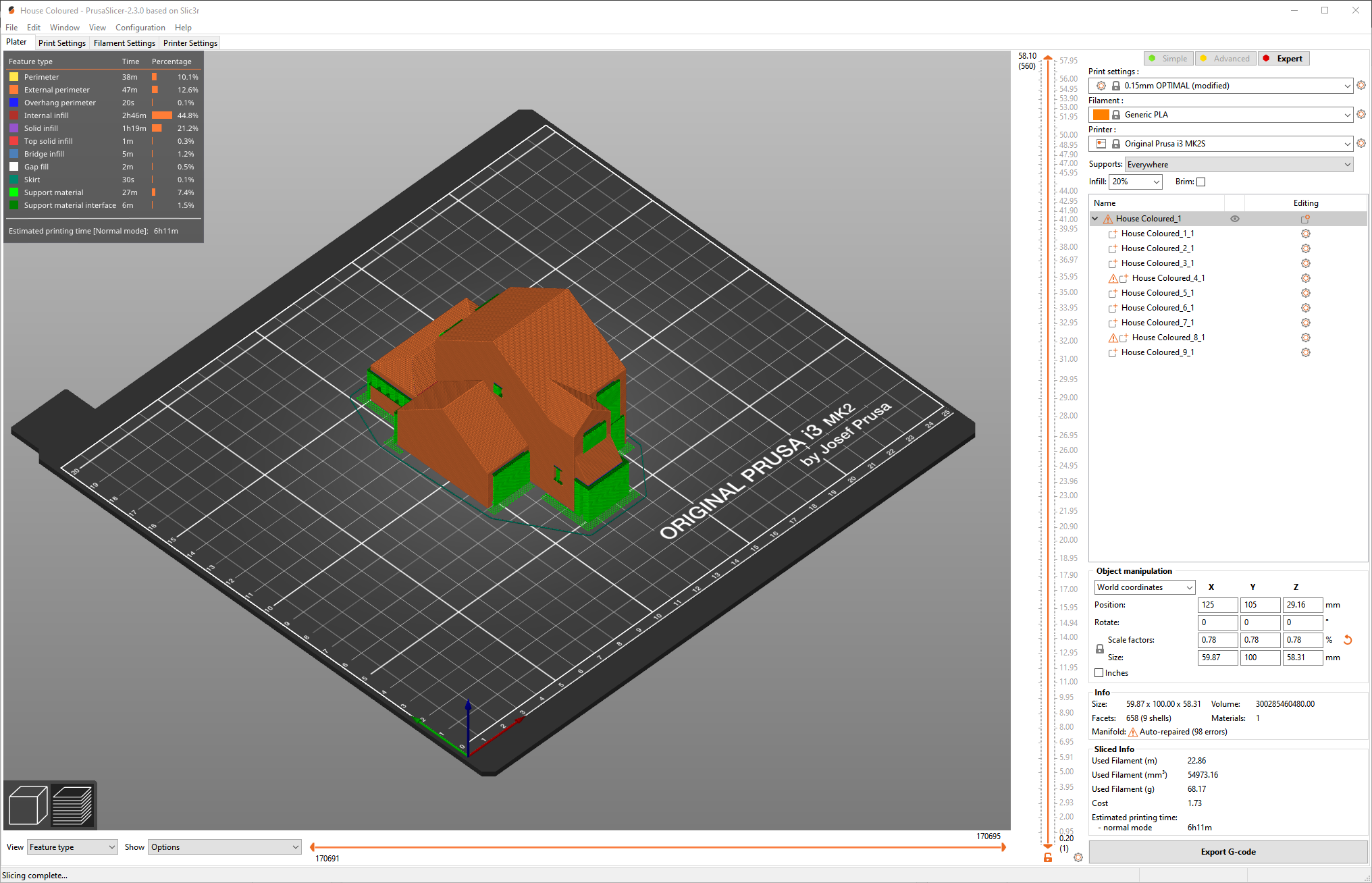
Click the Plater tab.
Click the Slice now button at the bottom right of the screen - Picture 4.
The support material is shown in green - Picture 5.
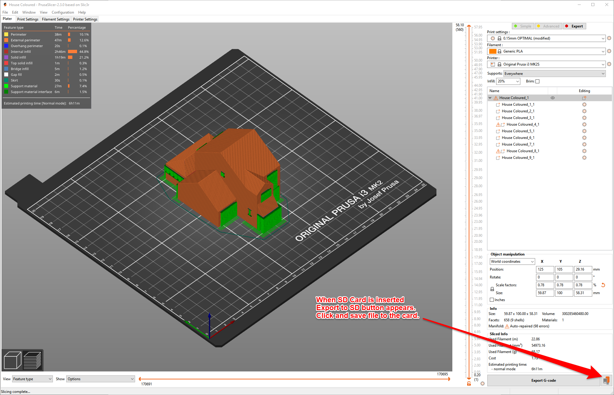
Insert an SD card into the computer. The Export to SD card button appears - Picture 6.
Click this and save the model to the SD card.
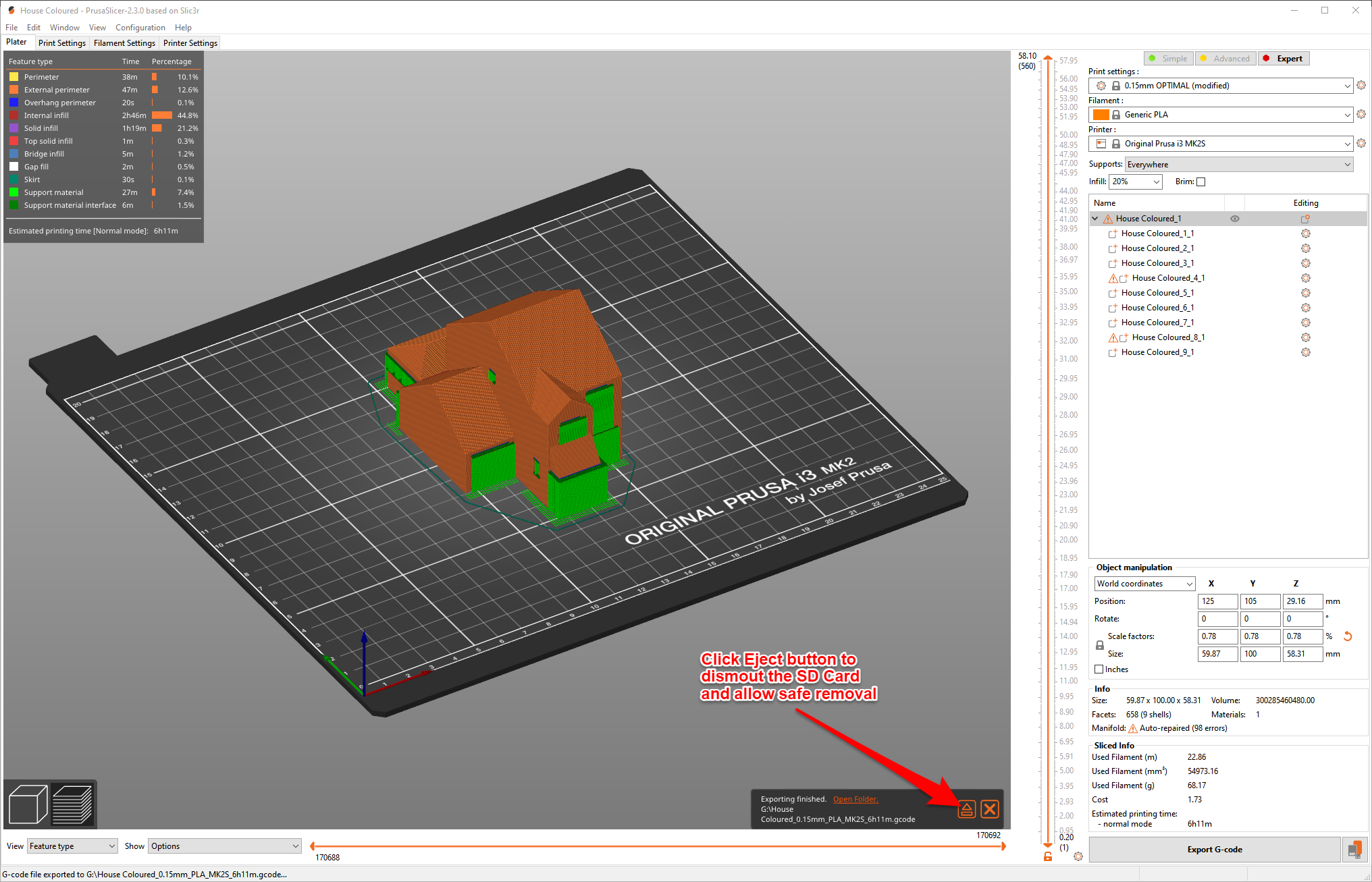
After saving, the Eject SD Card button will appear - Picture 7.
Click this and remove the SD card.
3D Printing the Model

For the Prusa i3 Mk 2 the procedure is as follows:
Pre-heat the printer for PLA.
Load the desired filament (in my case brown PLA).
Insert the SD card into the Prusa 3D Printer.
Select 'Print from SD'.
Select the House G code file and press the Go button.
Sit back while the printer produces the physical model.
Printing time at 0.15mm layer height is 6 hours 11 minutes.
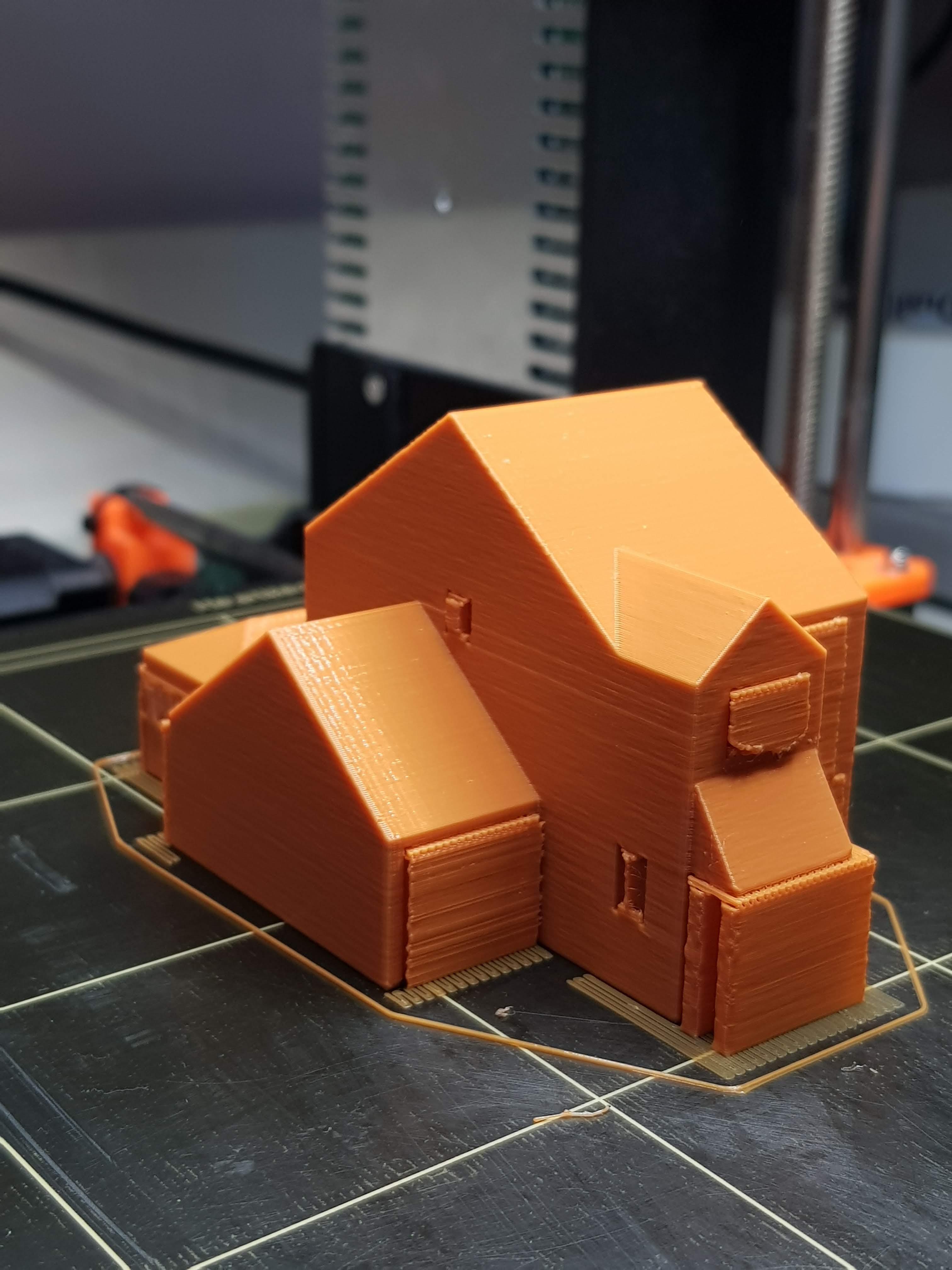
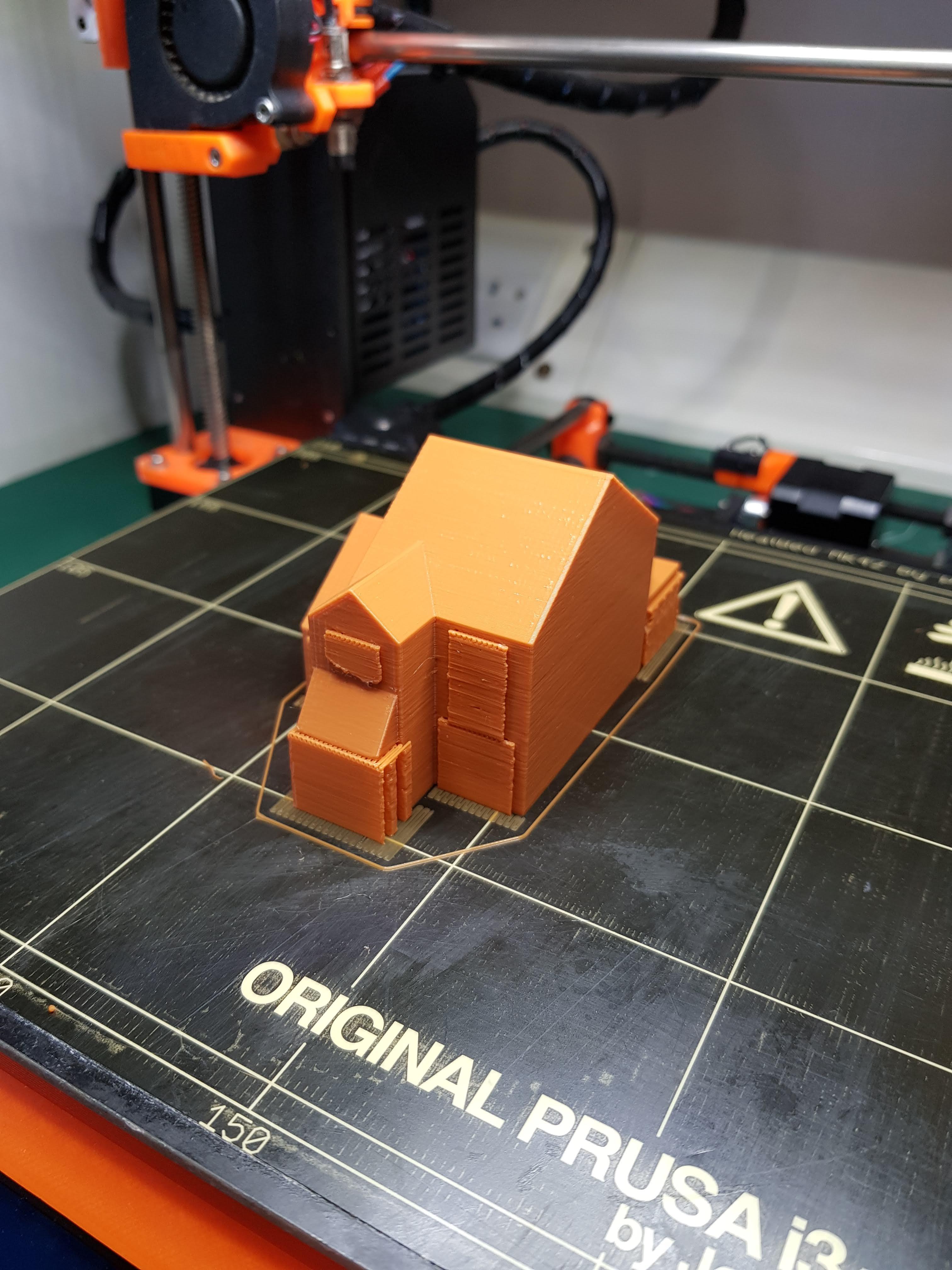
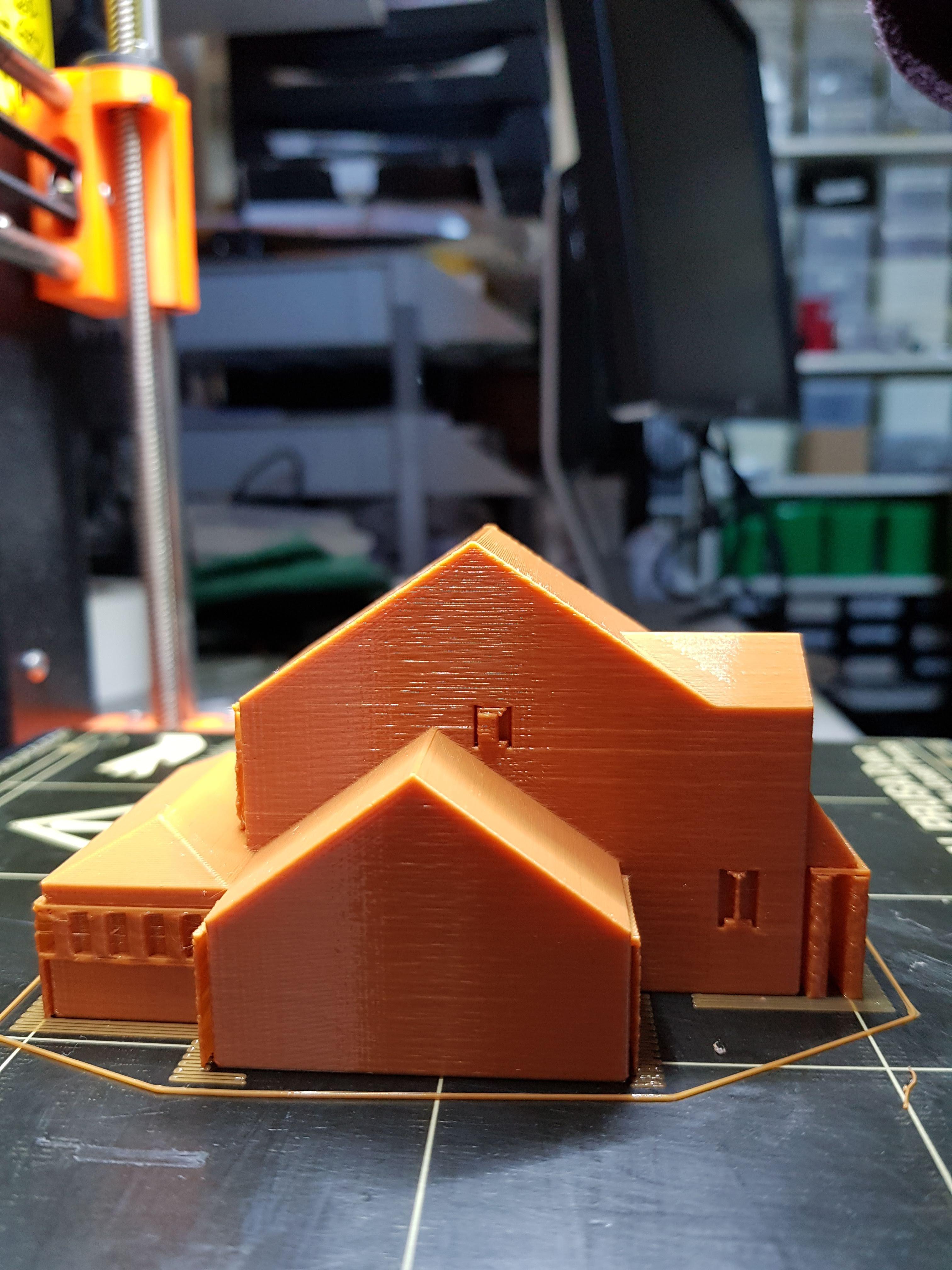
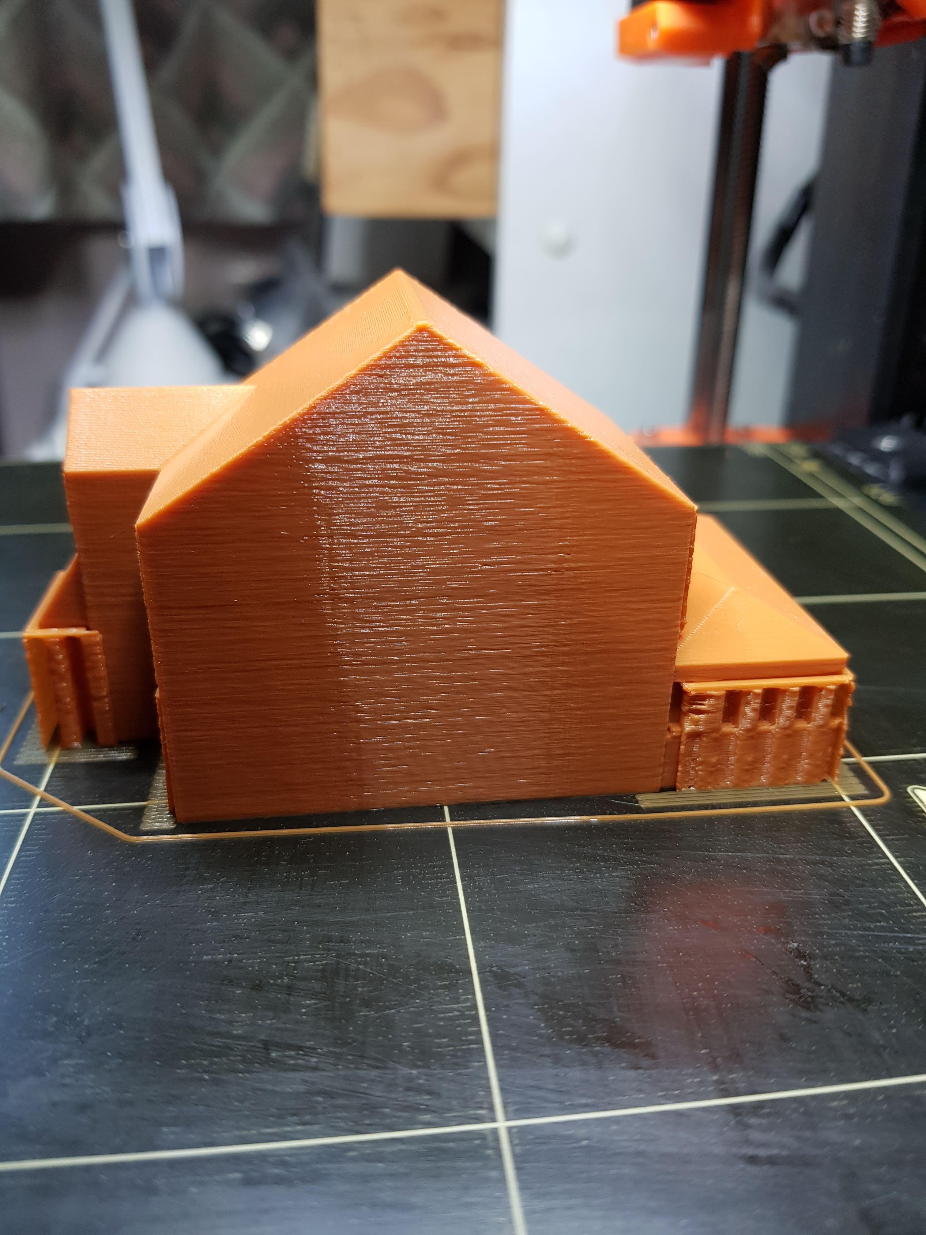
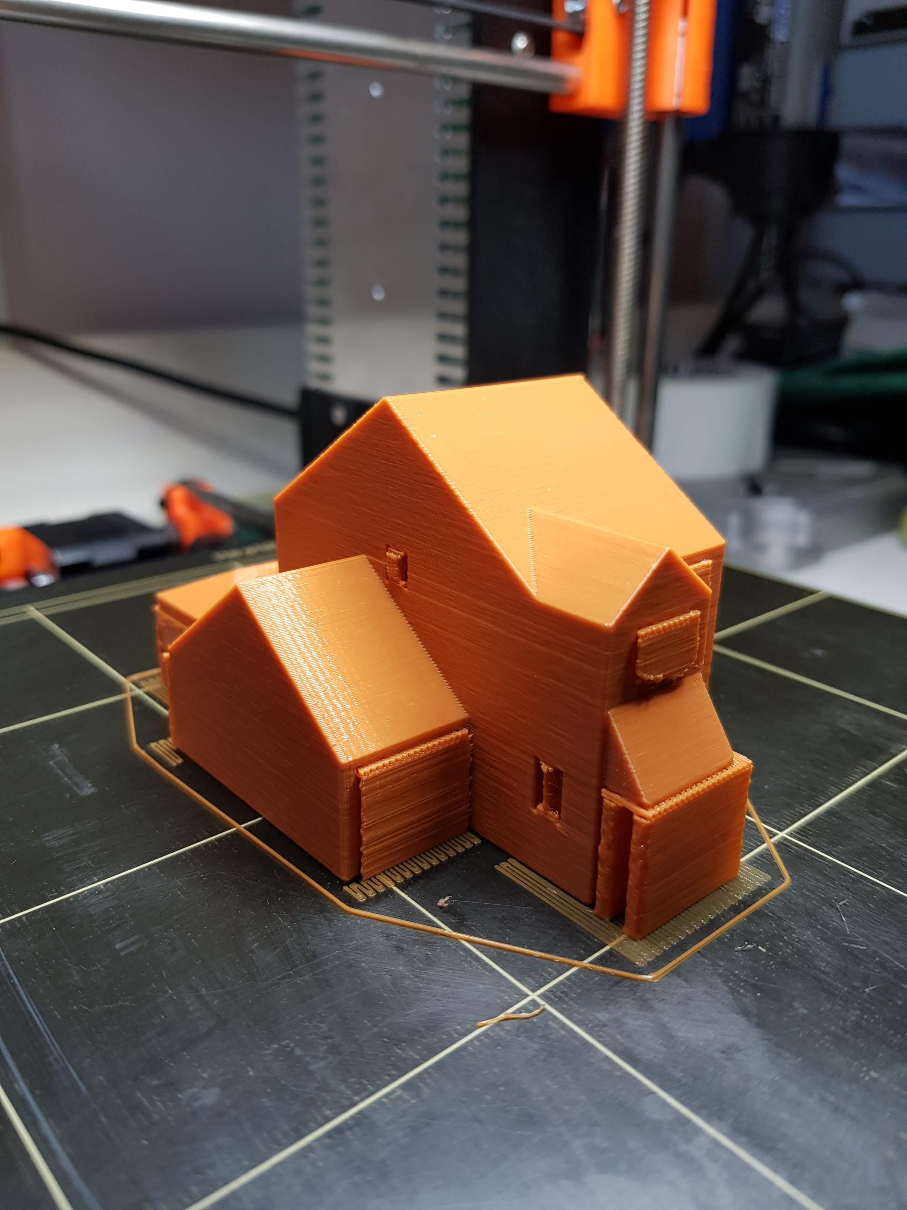
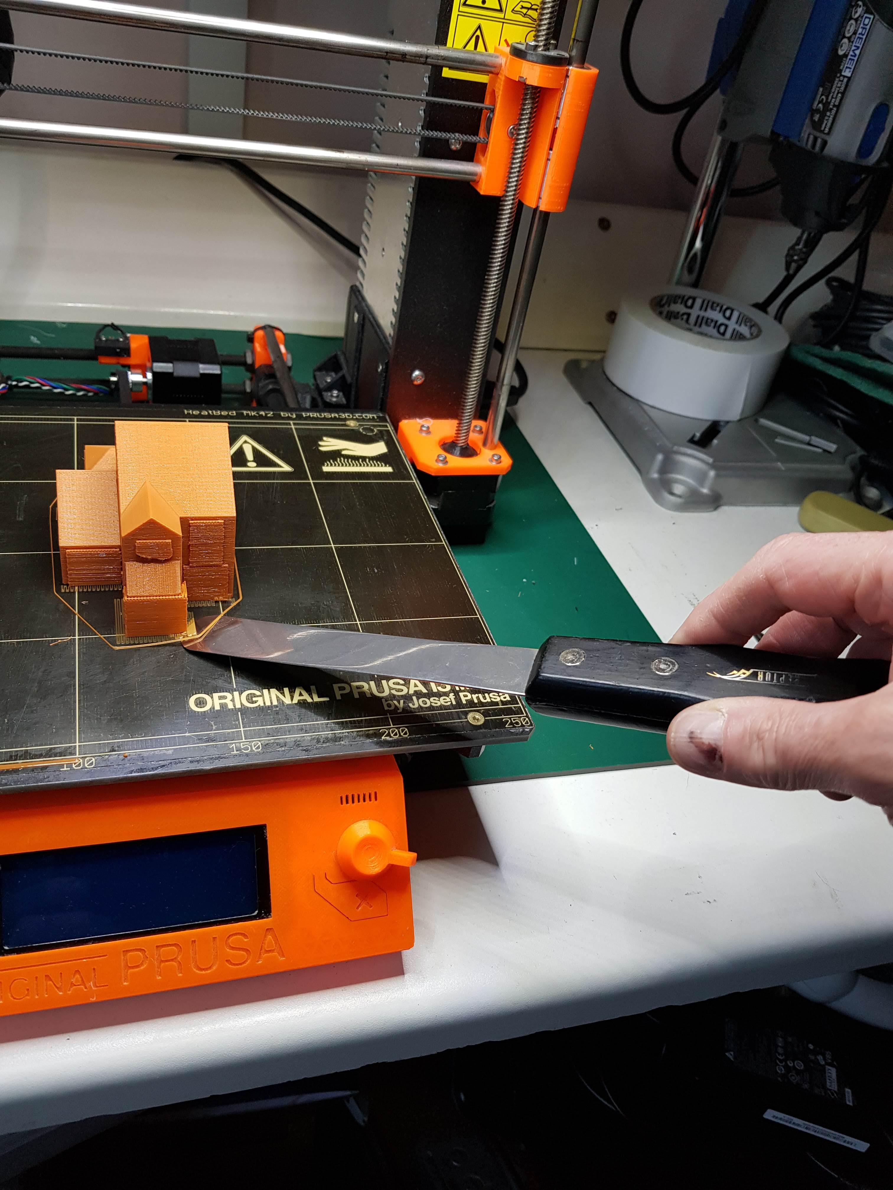
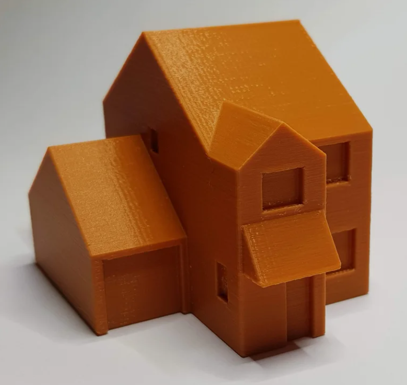
The finished print with support material is shown in the first five pictures.
Carefully remove the model from the print bed. I recommend using bespoke tools for this as they are less likely to damage the bed surface - I use a pair of tools from Reptor - Picture 6.
Remove the support material from the model - this breaks away easily.
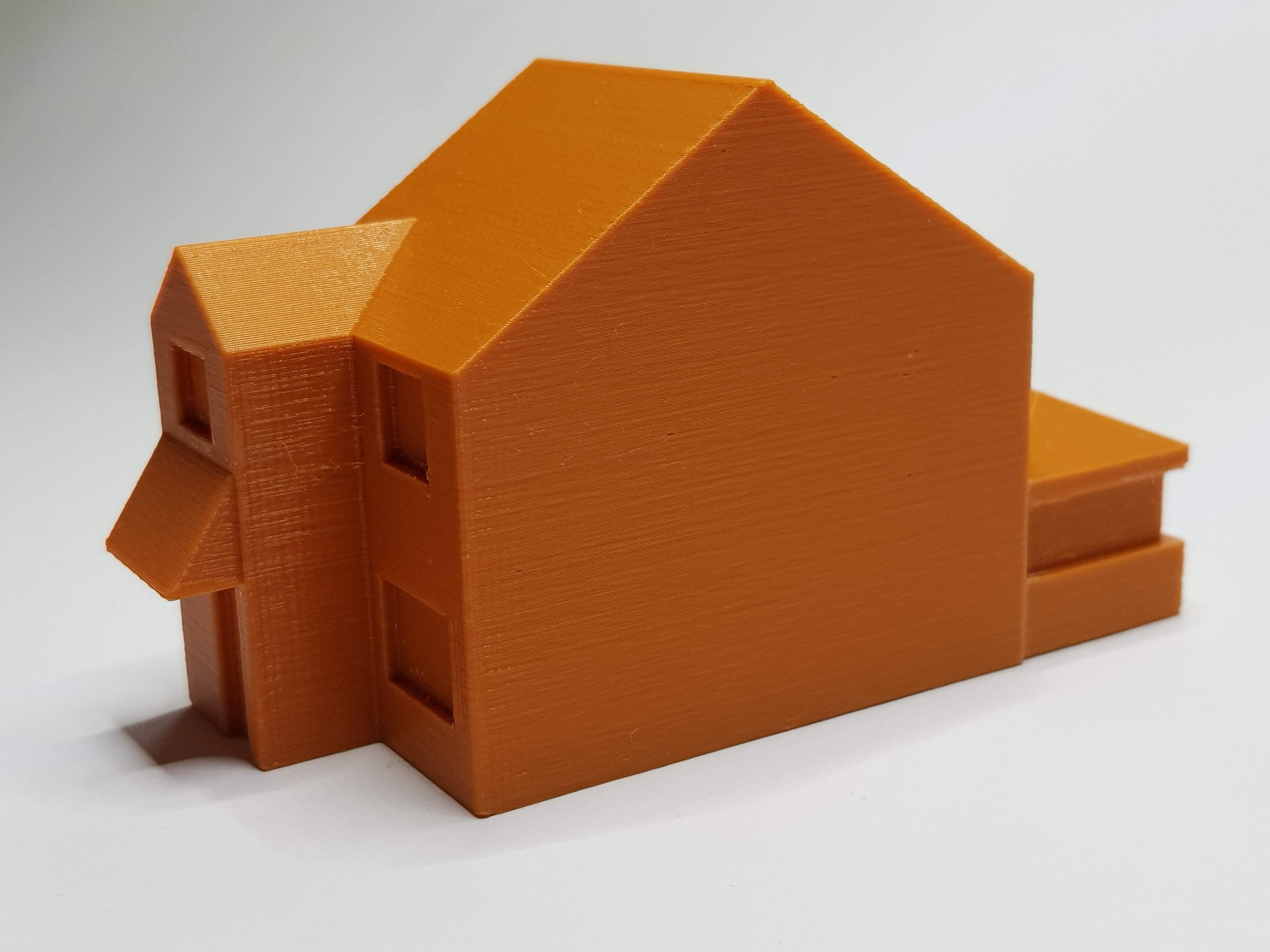
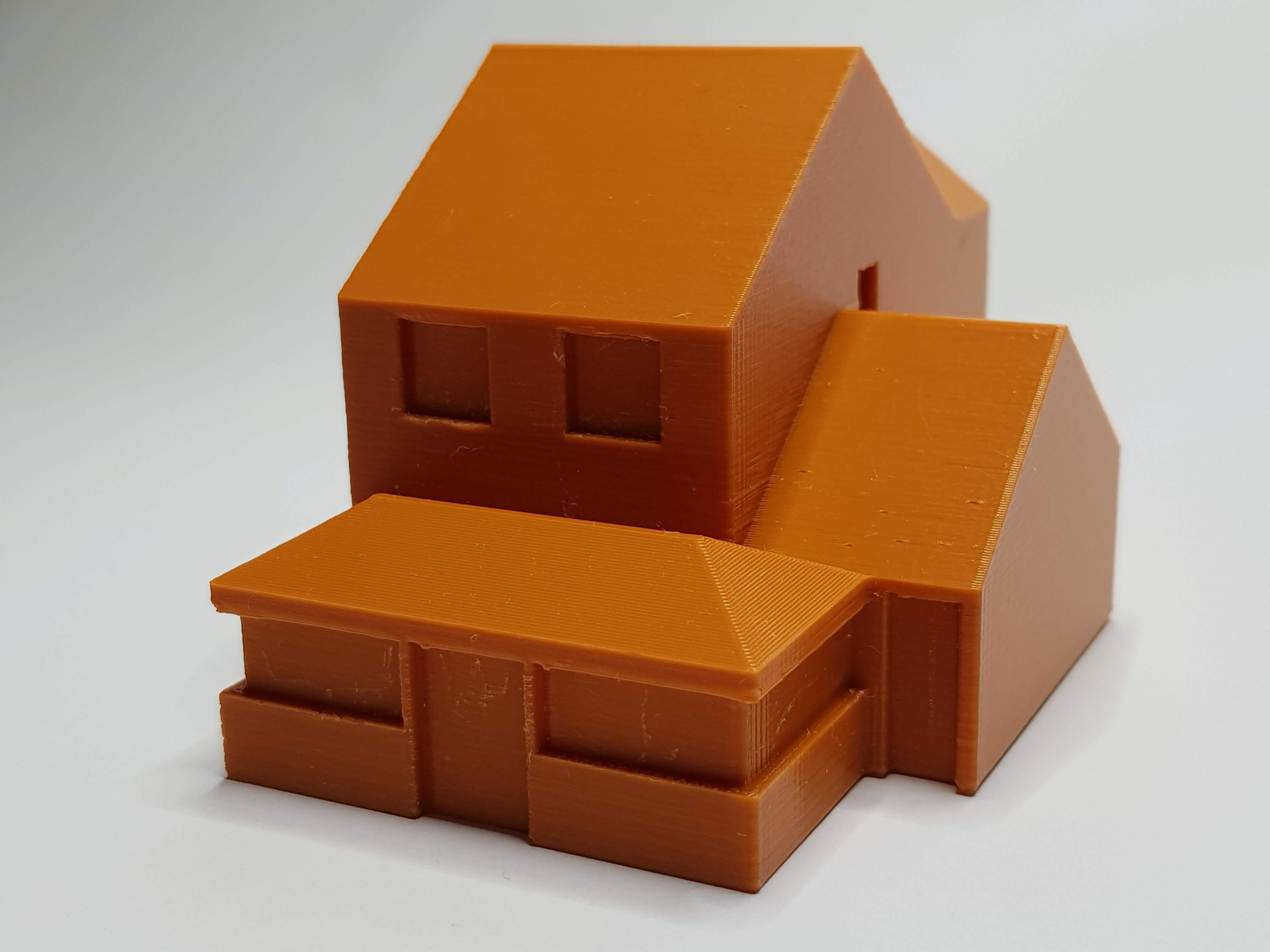
The final model is shown in pictures 7, 8 and 9.
Final Thoughts
Sue is very pleased with the model. For the first time she has a full appreciation of the shape of our home.
An insight into the world of the blind may be gained from Sue's comment on first feeling the model 'I thought the garage roof was the other way round.'!
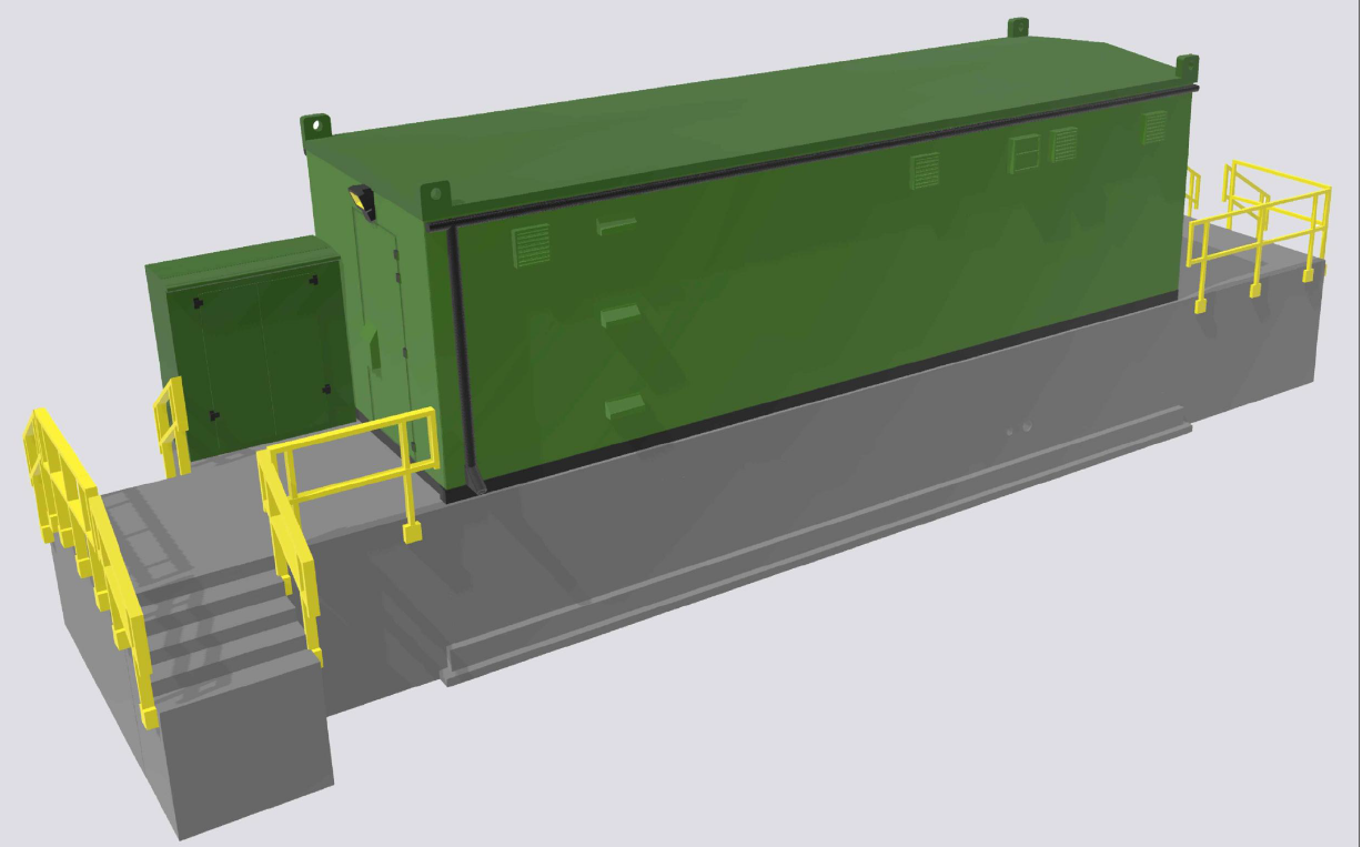
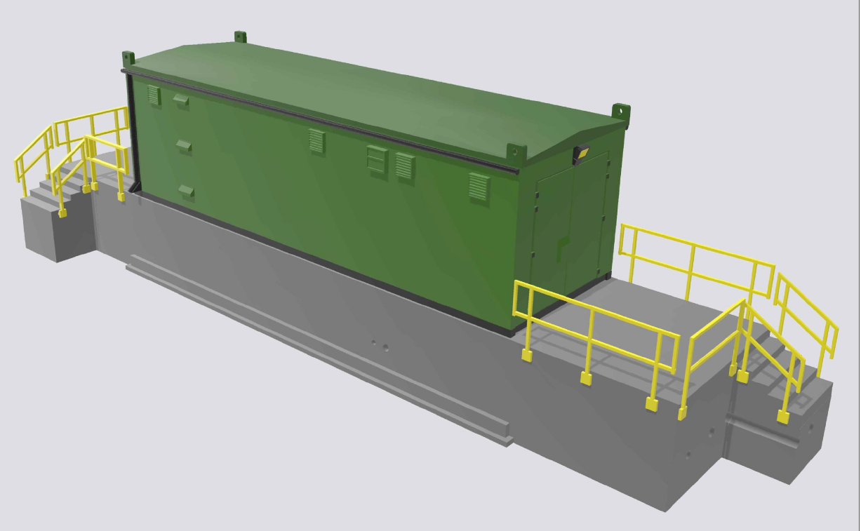
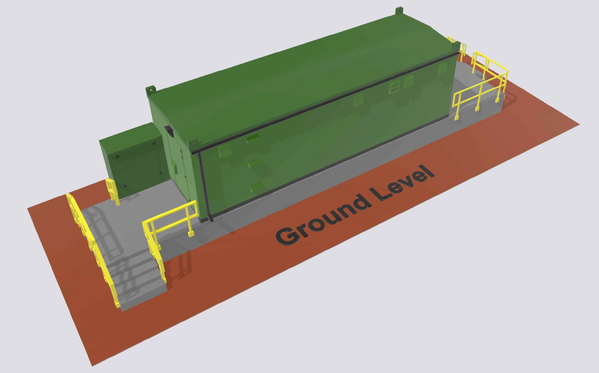
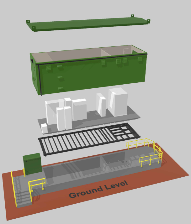
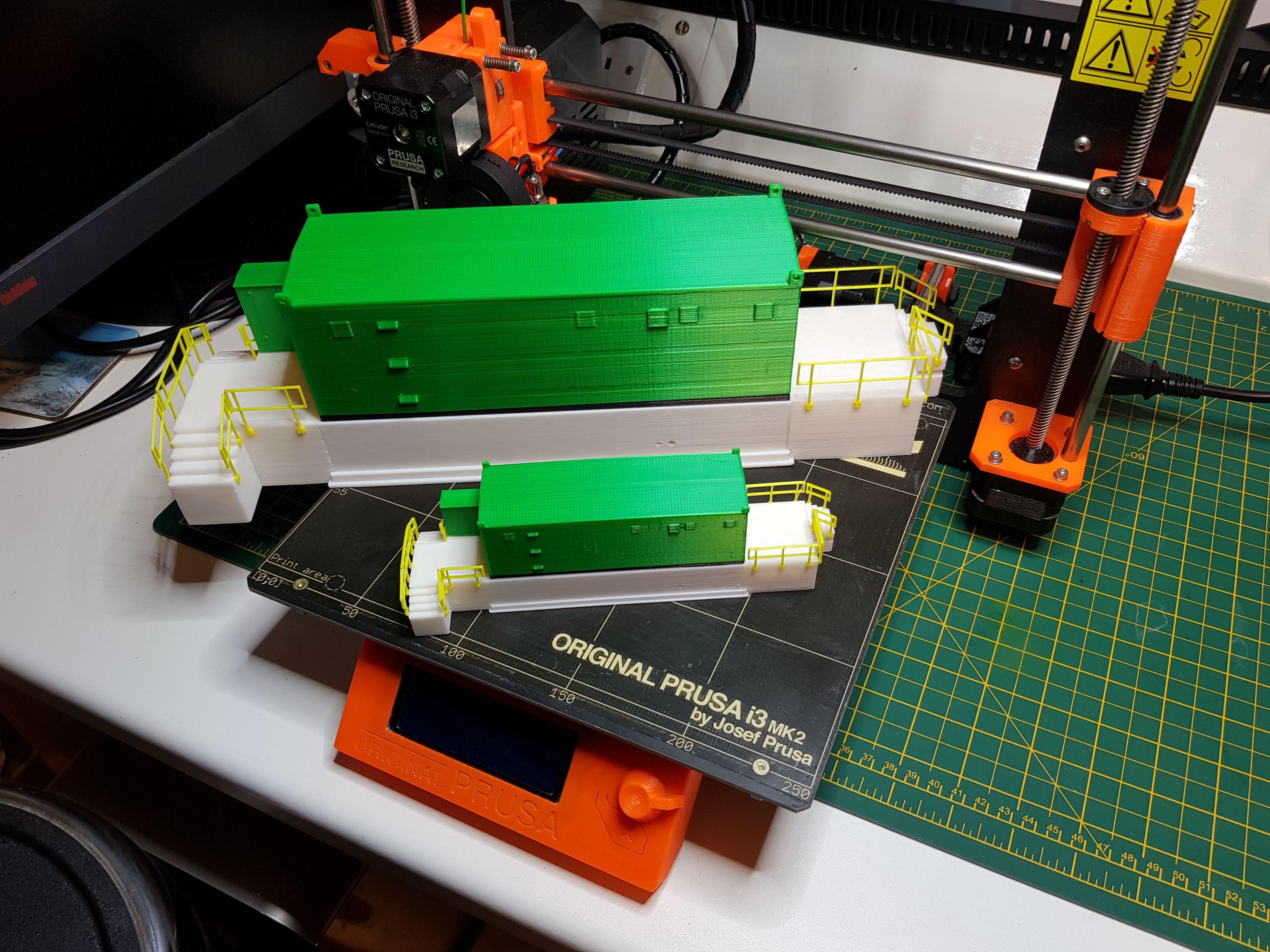
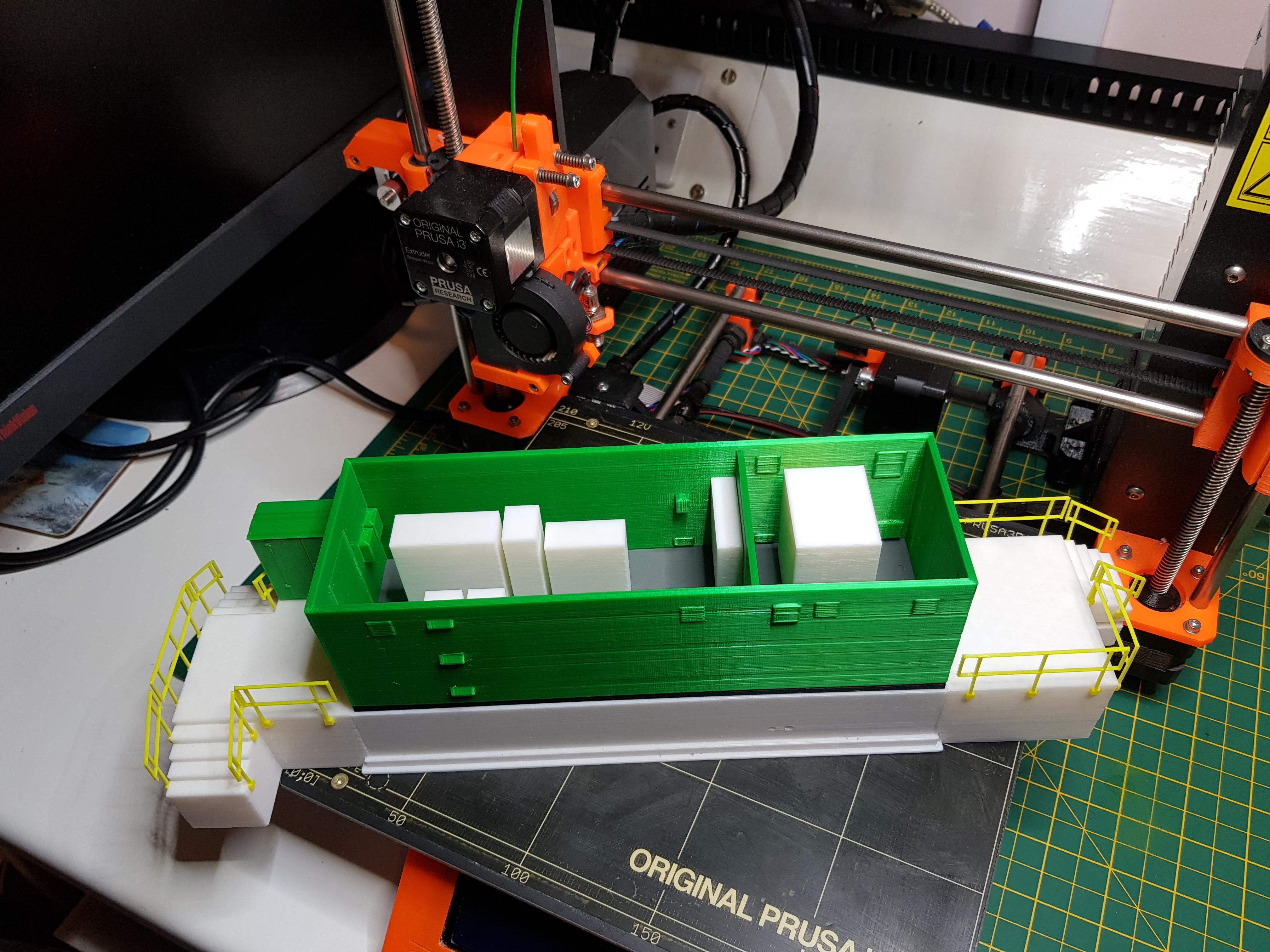
I hope that this Instructable will help anyone starting out in the world of 3D design with Microsoft 3D Builder. I have been very impressed with the capabilities of the program. I have used it to create (and print) more complex models such as the solar farm substation shown in the pictures attached.
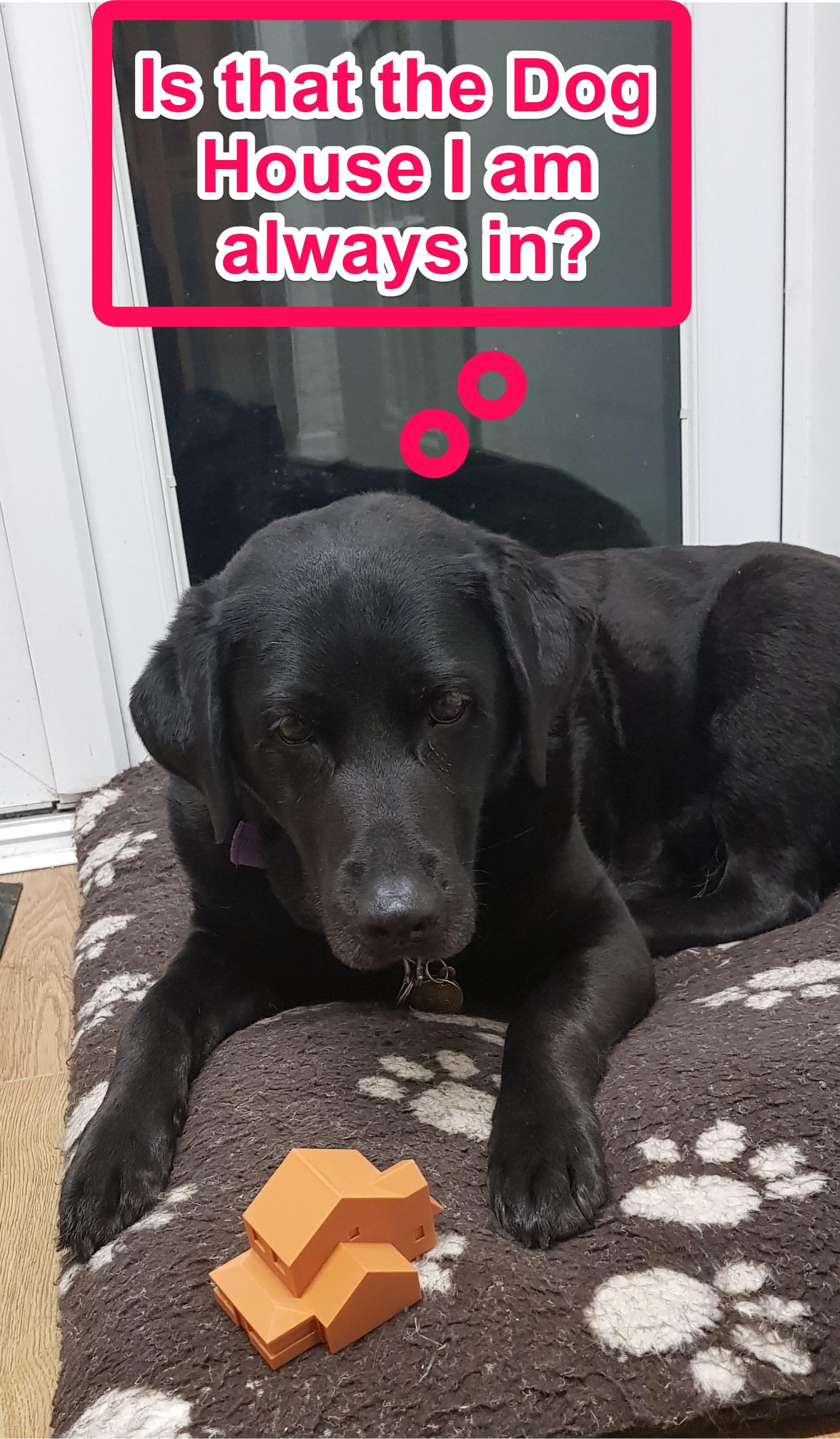
As always, Milly the Guide Dog has her say - see final picture.
This was my entry in the Big vs Small Challenge - and it won a First Prize! Many thanks to everyone that took an interest in this project.