Mini Game Console With ATTINY84 and OLED Display
by jacqueline.lam902 in Circuits > Microcontrollers
6767 Views, 8 Favorites, 0 Comments
Mini Game Console With ATTINY84 and OLED Display
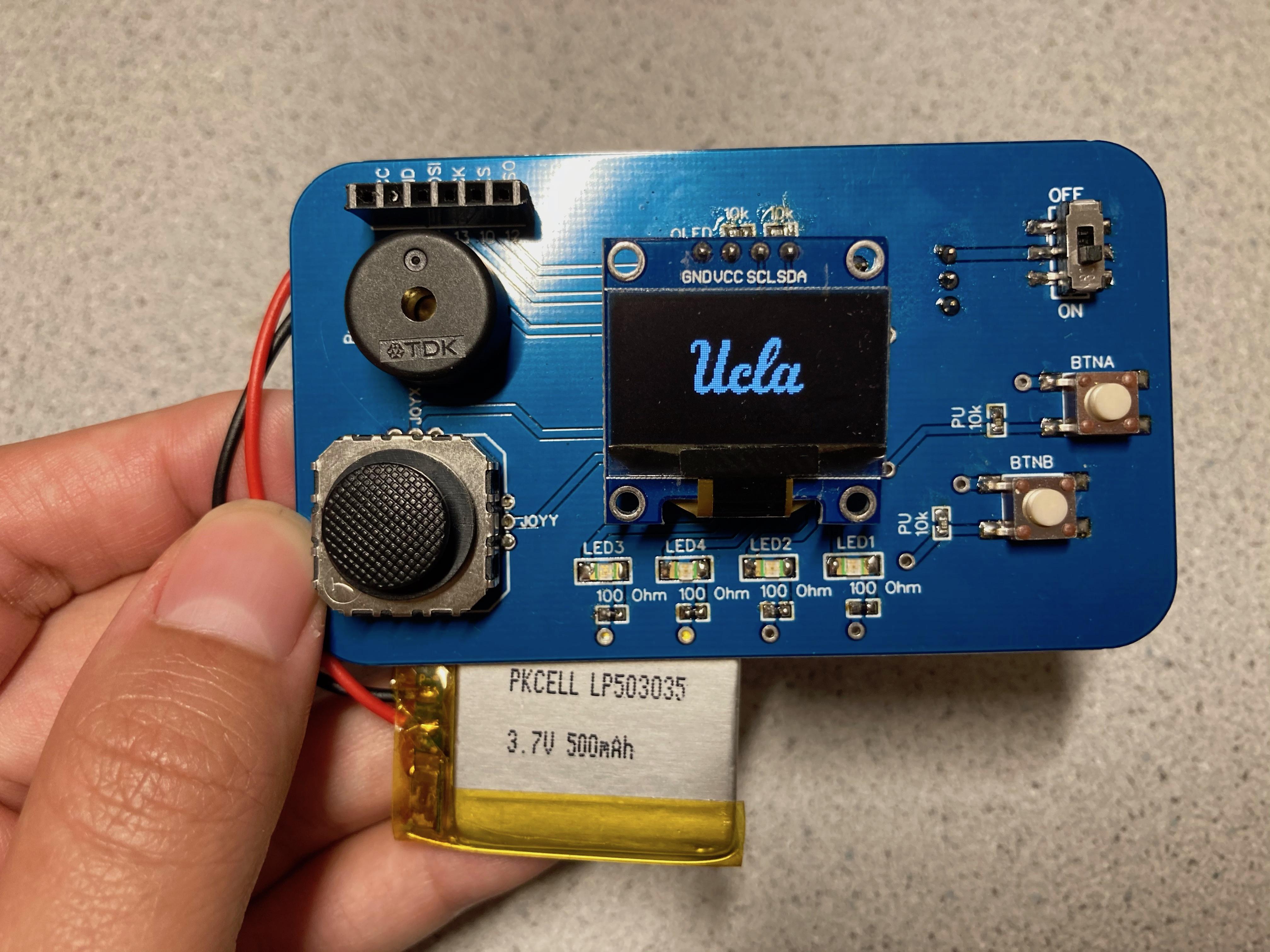
Follow this tutorial to create and customize your own ATTINY84 mini game console! Even if you are a beginner or pro hobbyist, you will be walked step by step from start to finish on how to create the PCB for the game console and program games onto your ATTINY84 microcontroller.
Differences Between ATTINY85 and ATTINY84


I found that there were many tutorials using the ATTINY85, but not a single one using the ATTINY84. One of the main differences is that ATTINY85 has 8 pins whereas the ATTINY84 has 14 pins, providing more flexibility and range.
Why ATTINY?
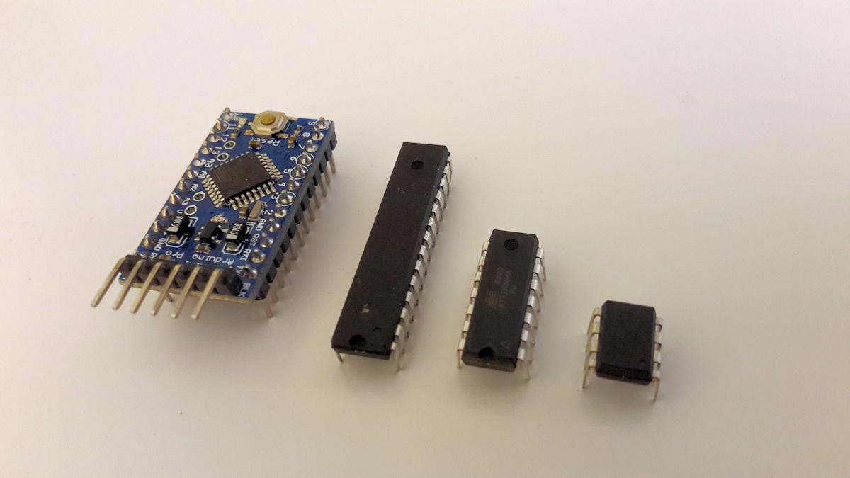
You might have used some form of an Arduino such as the Arduino Uno or Arduino Nano. However, if you wanted something more compact to use for a PCB, you would want to probably use an ATTINY (also known as TinyAVR) MCU. They are a subfamily of the popular 8-bit AVR microcontrollers, which typically has fewer features, fewer I/O pins, and less memory than other AVR series chips.
This is perfect for our mini game console that we will be creating! Later on, we will go over how to program the ATTINY84 using an Arduino Uno as an ISP (In-System-Programmer).
Parts Needed
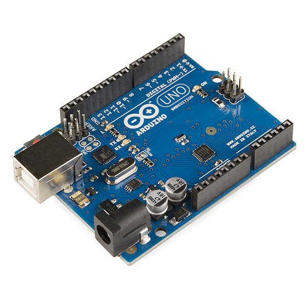
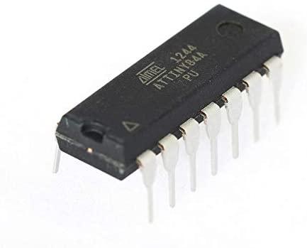
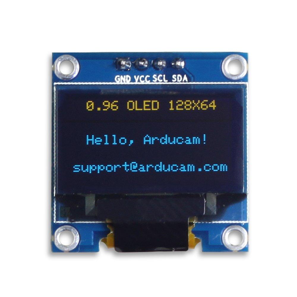
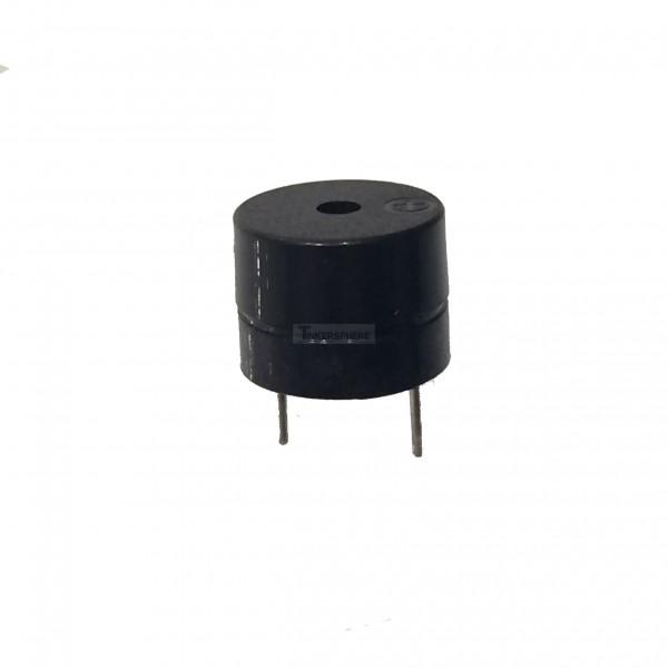
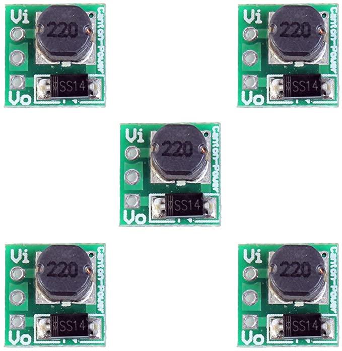
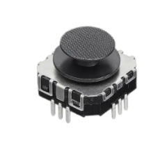
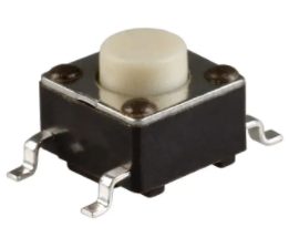
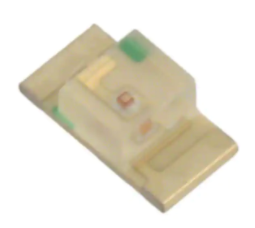
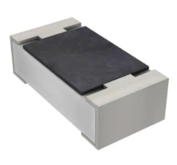
- (1) Arduno Uno or Arduino Nano
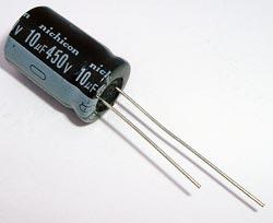
- (1) 10uF Cap
- Will be connected to RESET and GND of Arduino Uno
Game Console Parts
- (1) ATTINY84A-PU MCU
- (1) 128x64 OLED Display
- (1) Through Hole Buzzer
- (1) 5V Step Up Voltage Booster
- This is used to convert the 3.7V battery to 5V to power the ATTINY
- https://www.amazon.com/Comidox-Module-Voltage-Conv...
- (1) 2 Axis Joystick
- (2) SMD Push Buttons
- (4) 1206 SMD LEDs
- (4) 100 Ohm 1206 SMD Resistors
- There should be one resistor in series with each LED to limit current
- https://www.digikey.com/product-detail/en/yageo/RC...
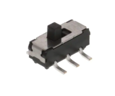
- (1) SMD Slide Switch
- To turn battery on/off
- https://www.digikey.com/product-detail/en/c-k/JS20...
- (1) 0.1uF SMD Capacitor
- One of the decoupling capacitors
- https://www.digikey.com/product-detail/en/yageo/CC...
- (1) 10uF SMD Capacitor
- One of the decoupling capacitors
- https://www.digikey.in/product-detail/en/kemet/C08...
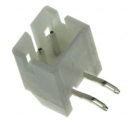
- (1) JST Connector
- Used to connect your battery
-
https://www.digikey.com/product-detail/en/440055-2/A100043-ND/2077946
- (4) 10K Ohm SMD Resistors
- (2) are pull up resistors for the (2) push buttons
- The other (2) are to pull up the SDA and SCL line connected to the OLED Display
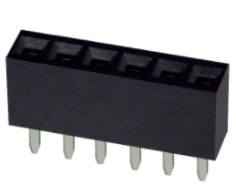
- (1) 6x1 Female Header (Optional)
- (1) 3.7V Battery
-
https://www.digikey.com/products/en?keywords=4236&v=1528
-
Programming the ATTINY84
You should first know how to program the ATTINY84.
The ATTINY84 doesn't have a programming port like the Arduino Uno or Nano do. So, you'll need to use a programmer to go from and to the computer and the ATTINY.
An in-system programmer (ISP) is a piece of hardware used to load programs onto the ATTINY. There are a few other ISP options dedicated to being a programmer, but we will use the Arduino Uno as the ISP since it is probably the easiest and you might already have one lying around.
Configuring Arduino Uno As a ISP (In-System Programming)
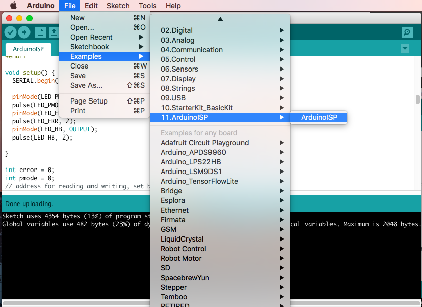
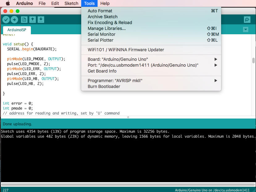
To program the ATTINY84, we need to first set Arduino Uno in ISP mode. Connect your Arduino Uno to the PC. Open Arduino IDE and open the ArduinoISP example file (File -> Examples -> ArduinoISP) and upload it.
Make sure the settings are set to the following when you upload the ArduinoISP sketch:
- Board: Arduino Genuino/Uno
- Programmer: AVRISP mkll
- The correct port
Once the sketch is uploaded, it should display "Done Uploading" at the bottom.
Add ATTINY URL
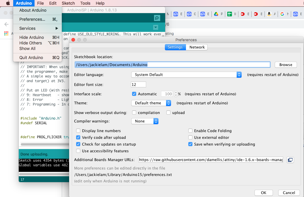
Under "Additional Boards Manager URLs", add "https://raw.githubusercontent.com/damellis/attiny/ide-1.6.x-boards-manager/package_damellis_attiny_index.json" at the end. If you already have URLs saved there, just separate them by a comma.
Installing the ATTINY Boards
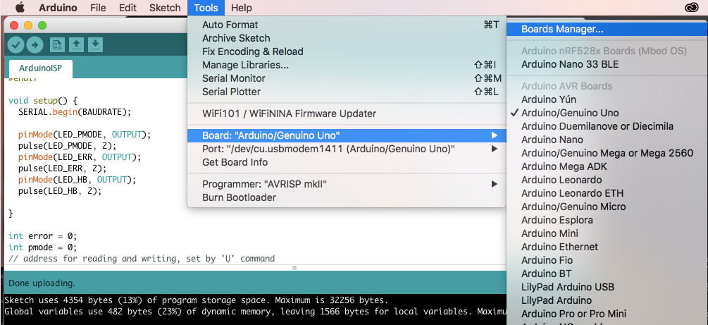

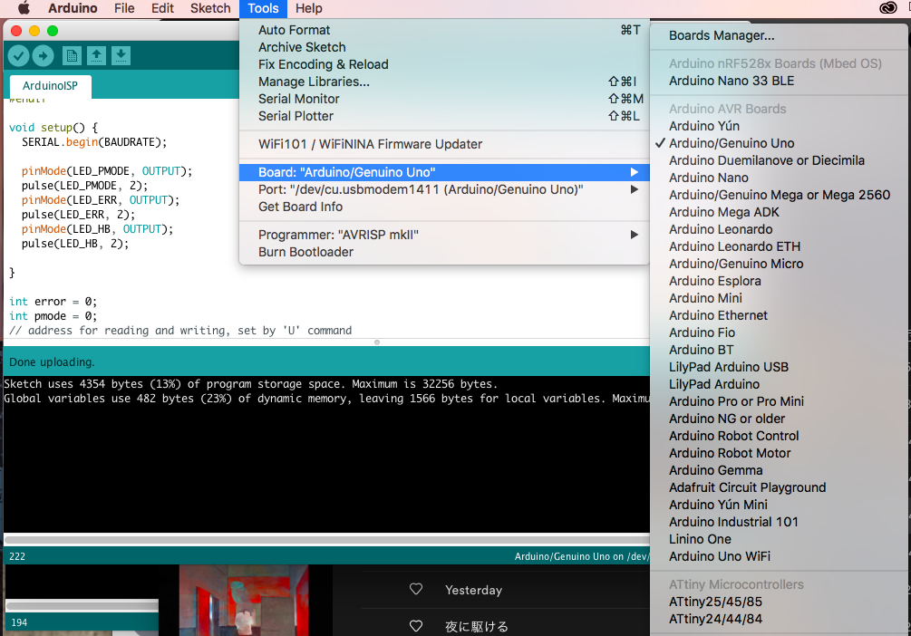
Then you want to actually install the board by going to Tools > Boards > Board Manager and search for "attiny". Click "Install" and once it is installed, verify by going to Tools > Boards, and checking if there is an option for "ATtiny24/44/84".
The Bootloader
Before you actually can upload a program to the ATTINY84, you will need to burn the bootloader to it first using the Arduino ISP. This only needs to be done once in the beginning when you get a fresh MCU, say from a vendor. If you have already done this, skip this step, step 9, and step 10 since they all pertain to the bootloader.
A bootloader is a special program used to load your program data onto the ATTINY MCU. This program resides in the MCU, and is the first program to inhabit an MCU when you power them up. It will also instruct the MCU what instructions to load or do next. The bootloader will allow you to load code from your Arduino IDE onto the ATTINY using a USB connection. Essentially, it is responsible for writing code on the chip as it arrives from the Arduino IDE.
More information on ISPs and bootloaders:
Wiring to Use Arduino As ISP
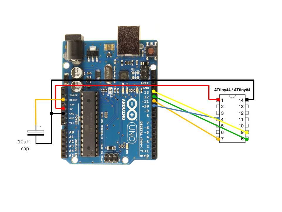
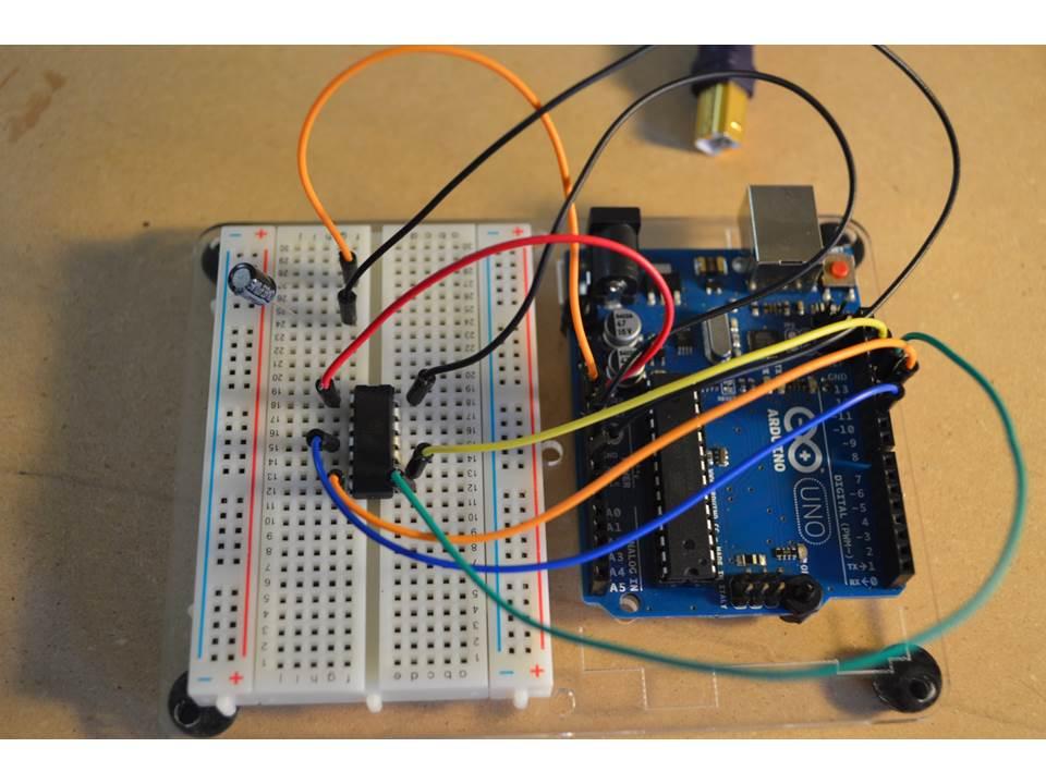
Now that we have downloaded the ATtiny package, and have prepared the Arduino Uno board for In-System Programming (ISP), we can burn the bootloader.
Make sure that the Arduino Uno is wired to the ATTINY84 accordingly. The capacitor prevents the Uno from resetting when avrdude opens the serial port as part of its auto-reset feature during each upload. The auto-reset is disabled to allow the programmer to access the ArduinoISP sketch on the Uno board.
Bootloader Configurations
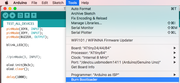
Before Burning the bootloader, be sure to have the following configurations:
- Processor: ATTINY84
- Clock: 8MHz internal clock
- Programmer: Arduino as ISP
Once you have these properties, click on "Burn Bootloader" and make sure it was done successfully.
More information on burning bootloader to ATTINY using Arduino Uno:
Uploading a Program to ATTINY84 (Using the PCB)
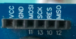
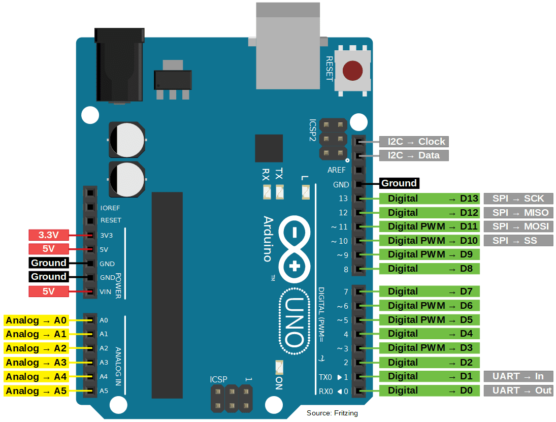
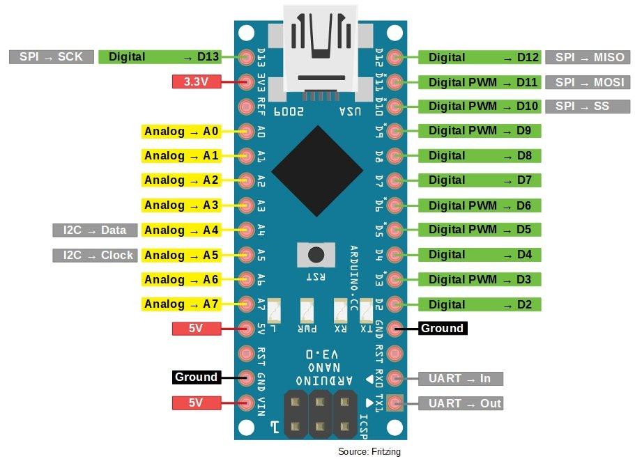
Now, we can upload an Arduino sketch to our ATTINY84 by connecting pins from the Arduino Uno to the 6 pin female header. On the PCB, there are labels 11,13,10,12 to denote that they are connected to the Arduino Uno pins 11,13,10,12 which correspond to MOSI, SCK, RES(or SS), and MISO pins respectively as seen on the pinout image.
You DO NOT need the capacitor at this step anymore; this was only required for the bootloader step.
If you have an Arduino Nano, you can use the pins labelled D11, D13, D10, and D12 instead of 11,13,10, and 12 since it corresponds to MOSI, SCK, SS, and MISO respectively. You would additionally just need to upload the Arduino ISP sketch to the Arduino Nano instead of the Uno.
Reference to programming ATTINY with Arduino Nano :
The sketch to upload onto the PCB is called tic_tac_toe.ino which is just the tic tac toe game using the PCB inputs such as the buttons and joystick and output of the OLED display.
If you want to program your own game, you can use the base sketch basic.ino which just defines the pin # for each peripheral and initializes them as an input or output.
Uploading a Program to ATTINY84 (Without PCB)
The schematic is the same as the bootloader step, except that you would just remove the capacitor. You can then upload the sketches from the previous step assuming you have the same components and that they are connected to the ATTINY84 according to the PCB schematic.
Designing the Schematic of the PCB
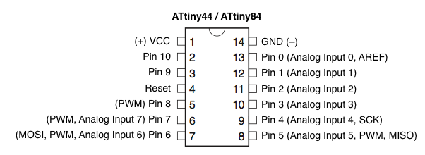
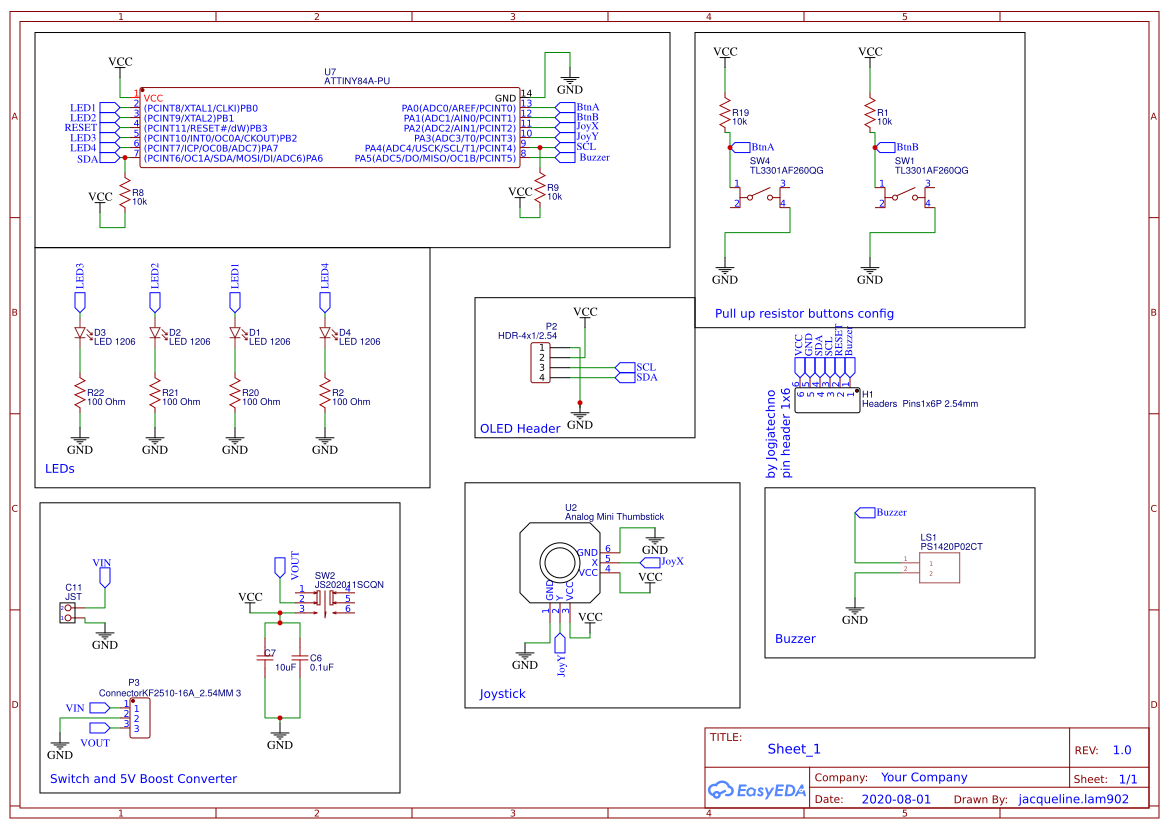
I used EASY EDA to design the PCB, but you can use any other software tool such as AUTODESK EAGLE. EASY EDA is really convenient because it is browser based so you don't need to download anything and you are able to create different versions of the same design in case you wanted to track your history. One really awesome ting about EASY EDA is that even if you made your board, but needed to make changes to the schematic, you can easily import those changes. Finally, you can share your project with anyone with just a simple link.
This mini game console revolves around the MCU, and in our case that is the ATTINY84. We first determine the pins we will need to program our MCU. Using the Arduino Uno as an ISP for our ATTINY84, we would connect the following using typical SPI pin configurations:
===========================
Arduino Uno Pin --> ATTINY84 PIN
===========================
5V --> VCC
GND --> GND
10 --> RESET
11 --> MOSI
12 --> MISO
13 --> SCK
You will also need a 10uF capacitor to connect between the RESET pin of the Arduino Uno and GND of the Arduino Uno.
These 6 pins will be accessed through a 6x1 female header.
Once we know what each pin represents, we can determine what peripherals can be attached to that pin. Looking at the diagram of the ATTINY84, there are 8 analog in pins and 3 PWM pins.
The peripherals being used are:
Output
- 4 LEDs
- Buzzer
- OLED Display
- Connected to SCL and SDA
Input
- 2 Push Buttons
- Joystick
- Must connect to analog in pin since it is internally made of 2 potentiometers
Board Layout
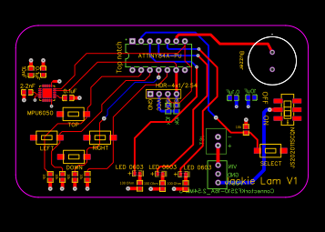
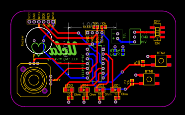
Here is the board layout that I have, but you can move pieces around however you like. One thing to make sure is to place your decoupling capacitors as close to the ATTINY as close as possible. When the DC Power supply is delivering the power to the circuit the decoupling capacitor will have infinite reactance on DC signals and they will not have any effects on them, but it has much less reactance on AC signals so they can pass through the decoupling capacitor and they will be shunted to the ground If required. The capacitor will create a low impedance path for the high frequency signals to get shunted resulting in a clean DC signal.
Link to EASY EDA Project: https://easyeda.com/editor#id=|40e5ed7a48ae4d6fb0...
.
Soldering
After you are done creating your PCB and have ordered it (I ordered mine from JLC PCB), it is now time to solder it. The first thing you want to check is if your ATTINY84 works by trying to upload any program using the Arduino UNO as an ISP connected to the corresponding pins of the female header on your PCB.
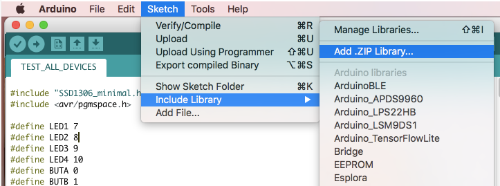
To use the OLED Display, you need to add the library "FSNKTHDIDWXMIF4.zip" by clicking on Sketch > Include Library > Add .ZIP library
You can download the .zip at this link:
https://drive.google.com/file/d/1Xne_BIvfmLPgJNrrZddyMp45wYfUHXZf/view?usp=sharing
To check that your components are working correctly, upload the sketch called "TEST_ALL_DEVICES.ino".
Once you have verified they work, you are now free to create any game you want!
Downloads
Creating a Custom Image on the OLED Screen
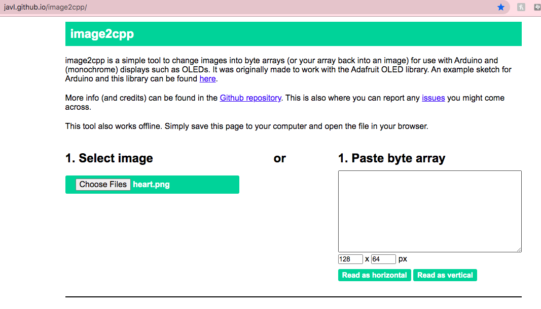
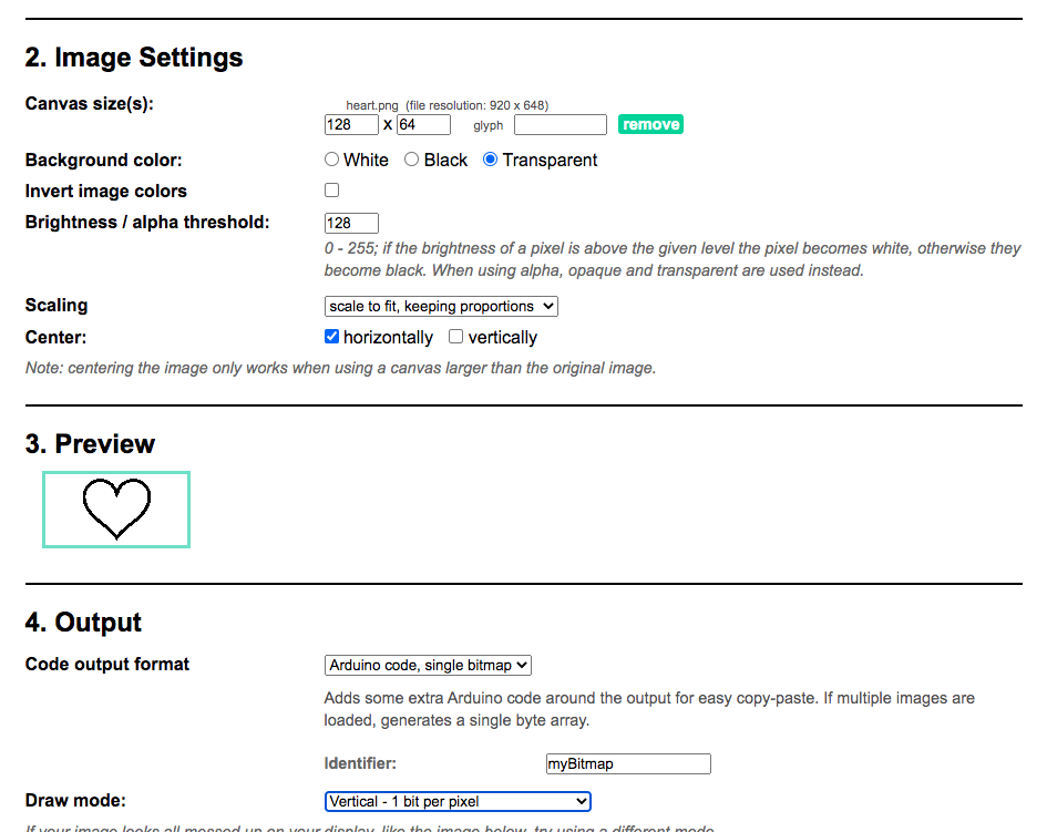
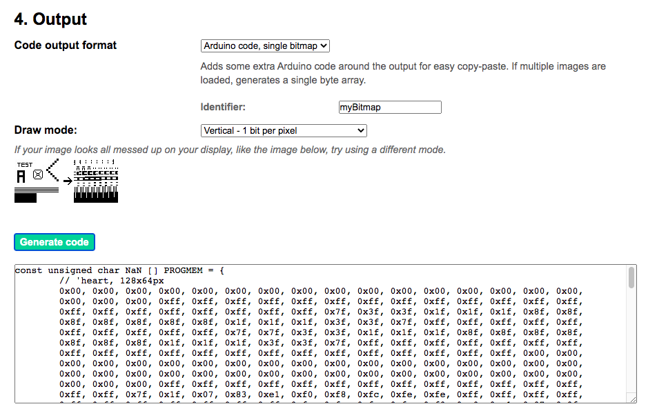
If you wanted a display like the image with the UCLA logo on the OLED screen, you can use this web app https://javl.github.io/image2cpp/ thanks to @javl on github! It basically converts that image into a byte array that you can put in your Arduino code. Here are the settings that I used to create a bitmap for a heart picture.