Mini Desktop Power Supply With ZK-4KX and HW-398 PD Decoy
by tekyinblack in Circuits > Tools
5874 Views, 52 Favorites, 0 Comments
Mini Desktop Power Supply With ZK-4KX and HW-398 PD Decoy

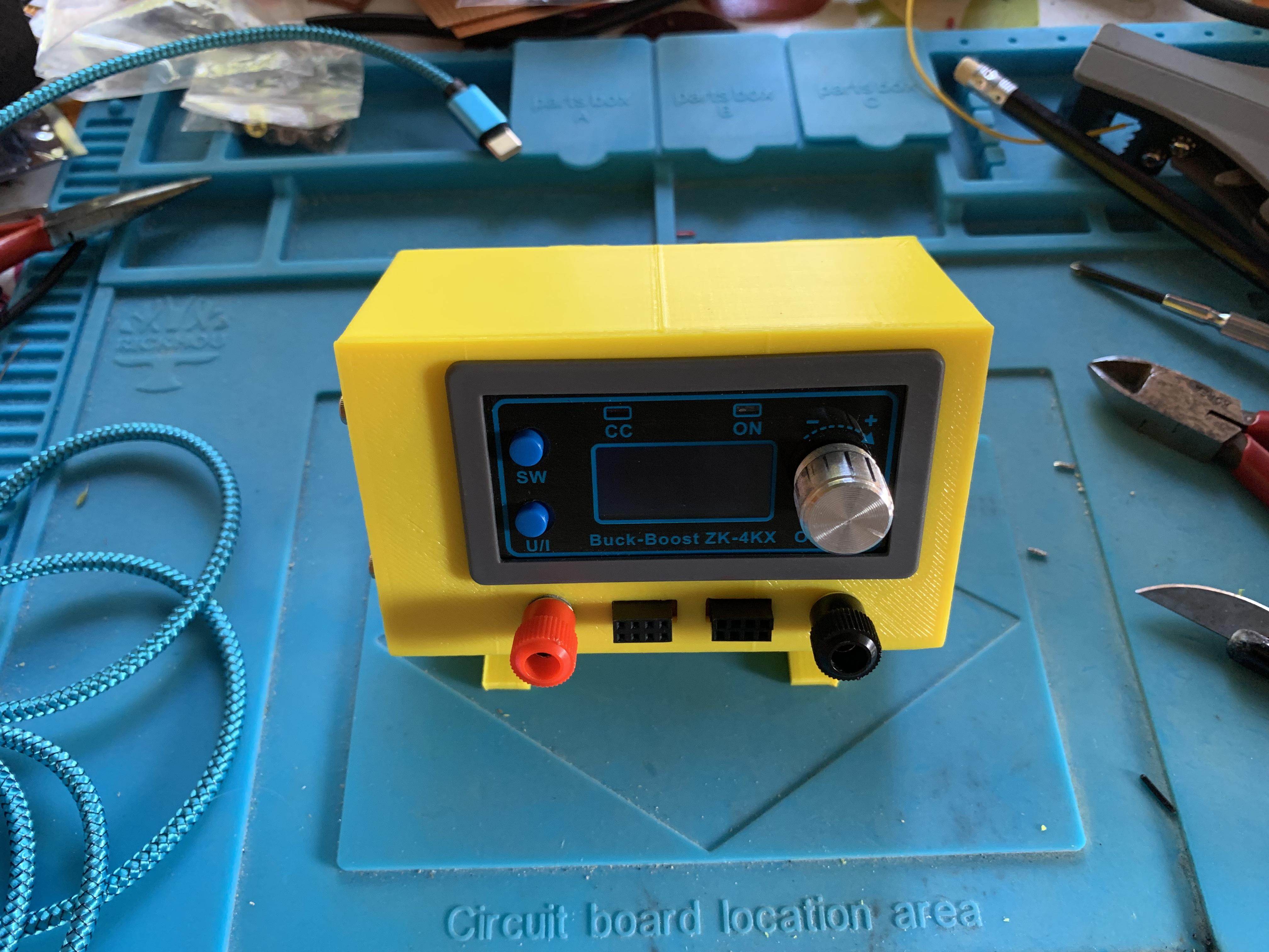
This is a mini desktop power supply I made to fit a gap in my toolset. It uses the ZK-4KX power supply module I've used previously in the tool holder power supply elsewhere.
These ZK-4KX variable power supplies are great for supplying power to small projects and this one takes up a quarter the space even a small mains power supply would take up, though with limited capabilities. However, space is key and this one is intended to be taken to places I won't have mains power, so will run from a USB-C connection. The USB connection is a HW-398 PD decoy module which will supply 5V as default but when connected to a USB PD socket, will negotiate a higher voltage and power level, in this case up to the voltage selected by a soldered link on the board. I chose 20V as the highest voltage as it reduces the current in the USB cable for any particular power level.
I invested in a 100W USB power supply for my desktop to run a wide variety of USB powered devices and reusing this to supply my circuits seems a good use.
There are are also similar power supplies that would fit the front panel but need a deeper case. The ZK-5KX and WZ3605E both have similar layouts but also are fitted with a rear fan. I've designed a case to fit these on TinkerCAD, but not part of this project.
Supplies


ZK-4KX power supply
HW-398 UCB-C PD decoy
4mm sockets red and black
two dupont sockets 2x4 female
hookup wire
40mm 5V fan
MH-MINI-360 buck convertor
stripboard offcuts
Print Case and Legs


Download and print the attached .stl files or access the TinkerCAD designs here.
Makeup the Front Panel Stripboard


This has been made up from a small offcut of stripboard to accommodate the dupont and 4mm sockets. It is fixed to the front panel using the 4mm socket posts. The holes in the stripboard were drilled through the front panel to ensure correct spacing.
Make Up the Fan PSU


As there isn't a fixed power supply in the case, the fan is fed from a small buck convertor turned down to about 4.5V output to drive the 5V fan. The buck convertor is first fitted with four pcb pins as standoffs and then to the stripboard, the fan and power supplies being soldered to the stripboard and a hole drilled to attached everything to the rear panel.
Fit the USB-C Socket


This is a HW-398 board which has no mounting holes in the PCB. To hold it in place, a plastic surround has been designed into the rear panel and a screw on holder is attached above it.
Before inserting it the input voltage cans to be set to 20V from it's default 12V if desired. To change from the default, first the 12V link shown in the picture must be de-soldered, and a new link inserted at the 20V position.
The power supply wires to the XK-4KX must also be attached.
Fit the Assembled Parts to the Main Box


Assemble the parts by first attaching the fan to the side of the case and screw the buck convertor board to the rear panel. Thread the cables through the front of the case and attach the rear panel.
Calibrate the ZK-4KX
If you are lucky, your module may not need any adjustment, but it's as well to test that the displayed voltages and currents are at least accurate.
- Connect the unit to a power supply capable of more than 12V and 1A, I used a previously built power supply.
- Set the input voltage to the unit to 12.5V
- Switch the unit on and with a meter measure the input voltage. Press the SW button until it displays IN, the two voltage should agree, if not then this voltage must be adjusted.
- Press the SW button until it displays OUT voltages, and with a meter, measure the output voltage. The two should agree, if not then this must be adjusted.
- Press the U/I button to enter the settings
- Press the SW button repeatedly until the IN CAL setting is displayed.
Wire the ZK-4KX


Attach both the fan cables and the power supply cables from the USB socket to the IN connectors on the ZK-4KX. Then connect the front socket panel to the OUT connectors, taking care to observe polarity.
Close the Case and Attach the Legs


Push the whole of the ZK-4KX into the front panel taking care to arrange the wires inside so as not to foul the fan blades. Fix the legs in place with two bolts if required.
Using

This has turned out to be very useful on my overcrowded desk, easy to connect and put into use, and then very easy to disconnect and put away. I do tend to hop between several common voltages, 3.3V, 5V and 9V though which is where my other power supplies come in, but I'm pleased with the size so will be looking to redesign a fixed supply soon along the same lines.