Mind Controlled Fan for ALS or Paralyzed Patients.
by BhuvneshT1 in Circuits > Wearables
9729 Views, 176 Favorites, 0 Comments
Mind Controlled Fan for ALS or Paralyzed Patients.
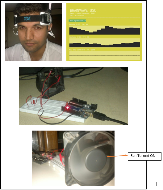
People with severe disabilities cannot interact with their environment as normal people. They always need assistance in doing small tasks like switching on a Fan or a TV. To bridge this gap between a patient and a switch there needs to be someway that does not require muscle movements. The best way I could imagine was the EEG technology. It means one can control a device by the use of his/her brainwaves without performing any physical movement.
For this I used a commercially available toy called Mindflex. It uses the same Neurosky EEG chip. I integrated it with a HC-05 bluetooth module and it was perfectly working as the NeuroSky MyndWave headset for one forth its cost.
In this Instructable I will show that how with the help of an Arduino and Processing I was able to control a Fan.
Parts You Will Need!!
- An EEG headset
I used Mindflex the toy headset as it can work the same as compared to other headsets at a reasonably very low price. You can get one at Ebay for as low as $15. - An HC-05 or HC-06 bluetooth module
It will be used to tweak the mindflex headset - $6. - Arduino Uno - $12
- A small fan
I used a small 12V computer fan for demonstration as it was lying around and fulfill the need. - Three small jumper wires.
Modify the Mindflex Headset
There are two sides to the headset. One side contains the batteries and the other contains the switch and the electronic circuits.
- Open up the side that has a switch on it.
- Remove the 4 screws to get access to the circuit board.
- Once inside, remove the 2 screws attaching the circuit board to the housing.
Now you need to solder three small wires to the circuit inside the housing.
- "T"(Transmit) pin on the chip
- One with the GND(ground).
- Third with the VCC (Power).
Check out the images for better understanding.
I hope your bluetooth module has come with female-female jumper wires. Now,
- connect the wire soldered to the T pin of the circuit with the RXD
- GND to GND
- and the VCC to the VCC of the Bluetooth module.
Now insulate everything and fix the Bluetooth module with the headset. Put batteries on the other side of the headset and switch it on. A Red light on the headset and a light on the Bluetooth module shows that its working.
Next step will be to set up communication between the headset and the computer to read EEG data from it.
Pair Bluetooth Headset With Computer
For pairing the Bluetooth module to the computer you can follow the steps given at this link.
Read Your Brainwaves Using BrainWaveOSC.
Now, Download BrainWaveOSC for your platform and unzip it to a folder.
Before you run the application, you'll need to identify how your system sees your bluetooth device.
Windows Users:
You need to find the COM port that the Bluetooth device is attached to. This link will help you to find your COM port to which the Bluetooth device is attached.
Once you find your device, open up the settings.xml file located in the Data folder of BrainWaveOSC.
The 4th line should read something like COM6 in between the tags. Change that to your device string that you found earlier.
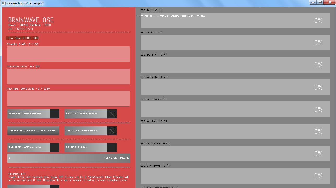
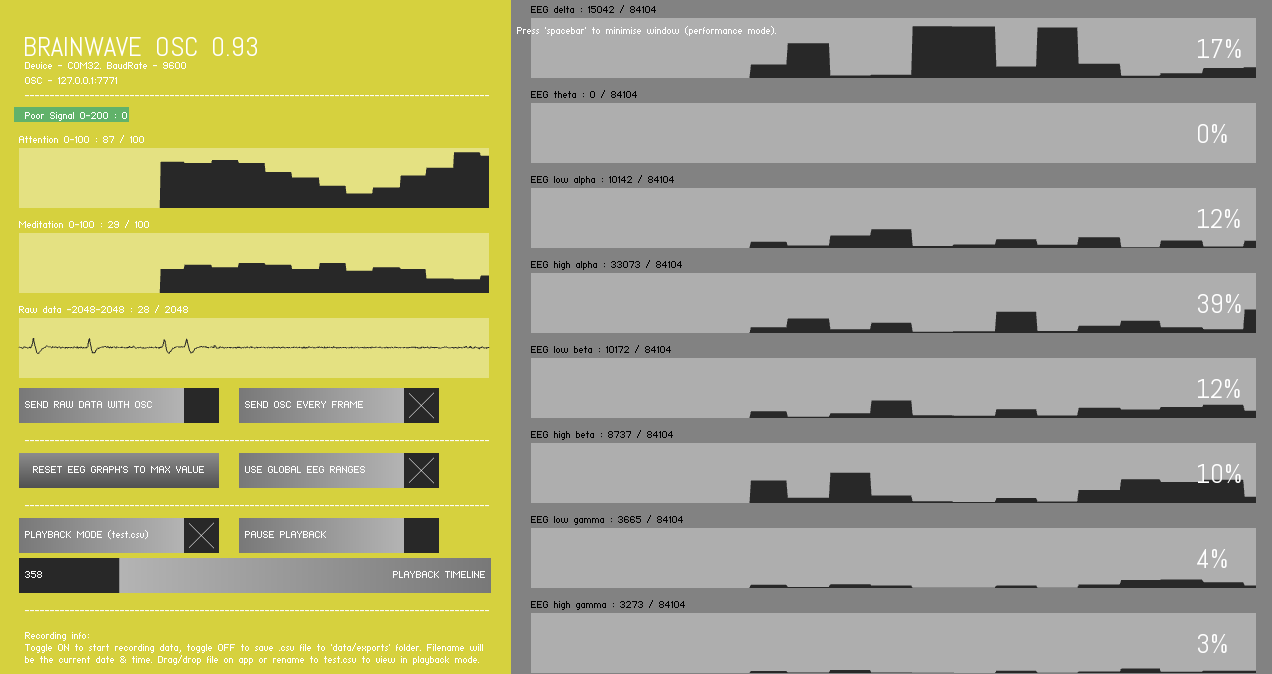
After you open the application, it should start with a red panel on the left and turn green once it starts receiving data. That's it, you are reading your brainwaves from the prefrontal cortex of your brain, which usually deals with logic.
Our next step will be to use this data to control a fan using Processing and Arduino.
Processing and OSC Messages
Processing is a free open-source programming language that is designed to be easy to use and is great for beginners. It is based on Java, so if you are familiar with that, you'll see some of the similarities.
Download it here and install it before we get started.
Now we have to parse data(OSC messages) received through BrainWaveOSC.
Start by opening up Processing and creating a new sketch.
Import the OSC Library
Starting from a blank sketch, you'll want to import the OSC library. You can do that by typing in:
import oscP5.*;
or
Go to Sketch->Import Library->oscP5.
If you can't find oscP5, you may need to add it first by going to Sketch->Import Library->Add Library... and search for oscP5. Once that is done, you'll want to create an empty object for it on the next line by typing:
OscP5 oscp5;
Create your setup and draw functions
This one is easy. Just type the following:
void setup(){
}
void draw(){
}
You've just created the skeleton.
Now that you have your skeleton, let's fill it in and start reading the OSC messages broadcasted by BrainWaveOSC. Make sure BrainWaveOSC is running and your headset is connected. You can tell by the color of the left panel. If it is green, then you're good.
Finding your OSC port
In BrainWaveOSC, look for your OSC port. In the upper left corner, you should see something like:
OSC - 127.0.0.1:7771
The 127.0.0.1 is your localhost ip address and 7771 is your port number. You'll need to save this port number for later.
Setting up Processing to receive OSC messages
Now you'll want to add this line inside your setup() function between the curly braces. Refer to the images as a reference.
Your setup() function should look like this:
void setup(){
oscp5 = new OscP5(this, 7771);
}
Great! You've just told the application to start listening on port 7771 for incoming OSC messages. Since it's in the setup function, it'll only run once at the beginning.
Receiving the OSC messages
Next we're going to create a function to receive the OSC messages. While setup() only runs once, and draw() runs all the time, the function we'll be creating will only be run when an OSC message is received.
Create a function that looks like this:
void oscEvent(OscMessage theMessage){
// Print the address and typetag of the message to the console
println("OSC Message received! The address pattern is " + theMessage.addrPattern() + ". The typetag is: " + theMessage.typetag());
}
Ok let's break it down.
void oscEvent(OscMessage theMessage) says that this function is called oscEvent, and it takes an OscMessage object as a parameter called theMessage. Ignore the void for now, it means the function isn't expected to return a value.
The second line is println,which is short for Print Line. This writes messages in the black area below your text editor when you run the application (called the console). The contents of println tell it to print "OSC Message Received!" and uses two methods of OscMessage:
- Address Pattern - This is like the subject of an email. It's the name of the message
- Typetag - This tells you what the contents of the message are
- For example, a typetag of iii means that there are 3 whole numbers inside the message
Run the application
- For example, a typetag of iii means that there are 3 whole numbers inside the message
Parse OSC Messages
What we need to do now is extract the numbers from the messages we've been receiving and do something useful with it.
For this, I'm only going to focus on the Attention value coming from BrainWaveOSC. So all we need to do is check our incoming messages for it and pull it out.
Inside your oscEvent function, you'll want to add:
if ( theMessage.checkAddrPattern("/attention") == true ) {
println("Your attention is at: " + theMessage.get(0).floatValue());
}
Awesome. So now we're receiving just the attention values and printing them to the screen. We need a way to pass this information to another function so that we can do something with it. The easy way to do this is with a global variable. Add this line underneath
OscP5 oscp5;
float currentAttention;
Change your oscEvent function to look like this:
if (theMessage.checkAddrPattern("/attention") == true) { currentAttention = theMessage.get(0).floatValue(); println("Your attention is at: " + currentAttention); }
Now, you've created a variable that can be accessed from any function and is updated when oscEvent sees an OSC message with the address pattern "/attention".
Arduino
Now, you are able to extract the attention values from the EEG data.
The next step is to send this value to your Arduino Uno.
- Connect the Arduino to your computer.
- Check the port number to which its connected to.
- Send values from the Processing to this port.
- Write a sketch that reads values sent from the Processing.
- Connect the Fan to any of the Arduino pins.
- Set a threshold value of Attention and make a trigger for the Fan to switch On and Off.